Oblique shaft construction offers alternative for slope crossings
Using an oblique shaft to cross slopes in pipeline construction can protect the environment, overcome difficulties related to slope stability, and save construction costs. Based on slope stability analysis, this article will present a new method to determine design parameters for oblique shafts traversing soil slopes, establishing all designed parameters for an inclined shaft crossing a simple homogeneous slope and discussing design parameters for a complex slope.
Cases will show that the new design method is practical and concise and will allow the inclined shaft to avoid the most dangerous sliding zone of a gully or slope during the design phase and for excavation to occur without obvious impact on slope stability. The design method could effectively avoid the stress concentration of pipelines caused by landslides.
The China Petroleum Pipeline Engineering Corp. has widely used inclined shaft crossings and their parameter design method, especially in loess areas, for both the already-operating Lan-Zheng-Chang oil transport pipeline and the second West-East natural gas pipeline, currently under construction.
Background
Long-distance oil and gas pipelines in China often cross through loess gullies, loess plateaus, and other complicated and varied topographies.1 The Lan-Zheng-Chang pipeline is the longest oil line in China and has more than 40 slopes just in the 97.4-km section in Zhengzhou district, Henan province.
Conventional burial in a loess slope environment destroys sensitive surface vegetation and causes soil erosion of the slope. Conventional burial in a loess slope is also prone to landslides, requiring advanced monitoring and integrity measures (OGJ, May 21, 2001, p. 62, and Feb. 17, 1986, p. 68). Even with such measures, however, landslides still cause heavy losses in loess slope environments engineering.
Contractors often use directional drilling to traverse high, steep slopes, but using this method in loess areas depends on topography and geological conditions. Drilling fluid can leak along cracks to the slope surface and unexpected releases of drilling mud can also damage the environment. Loess soil’s sensitivity to water can collapse the loess and reduces the stability of slopes or gullies.
A manually excavated oblique shaft can address these issues while gradually crossing large and medium-sized gullies on a loess plateau.2 3 Using a manually excavated oblique shaft not only protects the environment by avoiding large volume soil excavation, but also moderates slope instability and construction costs.
Inclined shaft
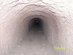
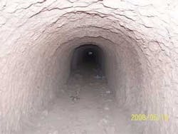
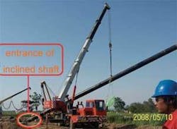
A Luoyang shovel allows experienced builders to excavate the oblique shaft at 4-8 m/day from slope top to slope bottom. A winch moves residual soil to the ground. Steel supports along the inclined shaft help avoid cave-ins and reduce the risks of manual excavation in bad geological conditions. Fig. 1 shows the inner view of an inclined well after manual excavation in Luoyang district, while Fig. 2 shows the pipeline entering the excavated well.
Ensuring the pipeline crosses a body-stabilized soil mass requires locating it outside the critical sliding surface. The main design parameters for spatial structure of well-traversing method include:
- Safe position of wellhead (entrance) and wellhead (exit) position at the slope top and bottom, respectively.
- Inclined shaft dip angle.
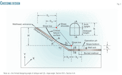
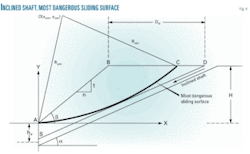
- Location of the operation pit at the bottom of slope (Fig. 3).
Reasonable design parameters ensure the security of the pipeline and the long-term stability of the slope both during construction and operation.
Design parameters
Soil slope stability analysis theory provides a new method for acquiring design parameters of wells traversing loess gullies or slopes. The method first determines the shape and location of the critical slip surface via slope stability analysis. Then, while avoiding the sliding block and maintaining slope stability, formulas for various design parameters of the well’s spatial structure are established.
According to stability analysis theory, whether in homogeneous or nonhomogeneous slope, the slide curve is a mostly regular and non-canonical dip surface or arc-like surface. The Swedish slice method or simplified Bishop method uses slope stability analysis4 to obtain the safety factor, center position, and radius of the critical slip surface for a homogeneous soil slope. The traditional slice method, however, cannot find the most dangerous sliding surface in complex topography.
The strength reduction method of numerical simulation can more realistically simulate gully topography and doesn’t need any assumptions regarding the location and shape of the sliding surface. Continuous discount of the strength parameters yields the most dangerous sliding surface, which may be irregular in shape or composed by a number of noncanonical potential sliding surfaces,5 allowing establishment of the formula for calculating the design parameters of the inclined shaft.
Dsp represents the horizontal distance from slope shoulder to the most dangerous sliding surface (Fig. 3). The distance between the wellhead at the top of slope and the slope shoulder should not measure less than 15 m.6
Elasticity theory and a large amount of numerical simulation analysis7 8 show the area of surrounding soil affected by excavation as 3-5 times the area of the excavated space size, allowing determination of hs and hv (Fig. 3).
Important design parameters for the inclined shaft include safe distance from the shaft wellhead to slope shoulder, dip angle and length, etc. Assuming the regular slope to be made of homogeneous materials allows conventional slope stability analysis methods to determine the circular arc of the most potentially dangerous sliding surface, with a circular center of O (x0m, y0m) and radius R0m.
The coordinate system in Fig. 4 yields Equation 1, describing the most dangerous sliding surface.
Assuming line SD, connected by the arch crown of the inclined shaft, passes through points S(0, hv) and D(xs, ys), and the included angle between line and the X axis is a, yields Equation 2 as the equation for line SD.
Equation 3 simplifies Equations 1 and 2 as line SD osculates with the most dangerous sliding surface.
Equation 4 provides the only tangential point between line SD and the most dangerous sliding surface.
The geometric relationship shown in Fig. 4 yields Equation 5 as the safety distance between the inclined shaft wellhead and slope shoulder and Equation 6 as the inclined shaft length.
The influence of inclined shaft excavation to the slope or gully, particularly for slope of safety factor near 1.0 (based on Equation 5’s results), show the inclined shaft should be moved parallel to the stabilized soil (the sliding bed of the most dangerous slip surface) at a certain distance in the design phase to avoid affecting slope stability.
Rewriting Equation 5 as Equation 7 addresses this influence.
Examples
The inclined shaft crossing method traversed 105 slopes and gullies in the 11th, 12th, and 13th sections of the Lan-Zheng-Chang oil transport pipeline in Henan province. The longest inclined shaft length measured 140 m. Two slopes crossed illustrate the parameter design method of the inclined shaft.
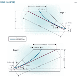
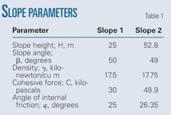
Table 1 shows the slope geometry and mechanical parameters7 of the two slopes, with analysis results shown in Fig. 5 and Table 2 for an inclined-shaft cross section height of 1.5 m.
Because the cross-section height, h, of the inclined shaft is 1.5 m, the vertical distance hv between the inclined shaft exit and slope toe can be determined as 3.0 m (>(3~5)h/2). Keeping the inclined shaft route osculate with the critical surface allows calculation of the inclined shaft’s position and the horizontal distance, hs, between the inclined shaft and slope toe.
The slope’s safety factors are close to 1.0, which is in a limit equilibrium state. The inclined pipeline shaft must therefore lie outside the potential sliding surface, and its design parameters should be adjusted with Equation 7. The safety distance between wellhead and slope shoulder increases by hv m, and the inclined shaft overall moves parallel to the stable soil in hv m.
Verifying the rationality of the acquired design parameters used numerical simulation analysis on Slope 1 for inclined shaft traversing engineering. The Duncan-Chang model reasonably reflects the non-linear deformation characteristics of soil masses.9 The Mohr-Coulomb reflects the yield degree of soil mass (Equation 8).
The limit designing dip angle of the inclined shaft measures 34°; other design parameters are shown in Table 2. The geometry model is fixed at the base and horizontal direction of the lateral face. Table 3 lists the main physical and mechanical parameter domains of the loess soil in the numerical simulations.
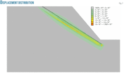
Fig. 6 shows the yield distribution of the slope after the inclined shaft crossing. The pipeline well lays safely outside the red and orange yield areas at the foot of the slope (as determined by the acquired design parameters) where the most critical slip surface lies. Figs. 6 and 7 show little effect of excavation on slope stability.
The design parameters are rational, and the method proposed to determine design parameters for pipelines traversing the slope was useful and concise.
References
- Yong, Z., “Oil & Gas Pipeline Crossing under Loess Gulch-Rock and Soil Mechanics,” Natural Gas and Oil, Vol.15, No.3, pp. 40-42, 1997.
- Guojian, L., “Oblique Well Crossing Method—A Pipeline Construction Method in Loess Plateau,” Petroleum Engineering Construction, Vol. 33, No. 3, pp. 23-25, 2007.
- Jiafu, C., Jidong, Y., and Jianshe, P., “Method of Lay Down Pipeline with Drilling Inclined/Vertical Well at the Steep Location,” Petroleum Engineering Construction, Vol. 26, No. 5, pp. 19-21, 2000.
- Shude, Z., “Soil Mechanics,” Beijing: Advanced Education Press, 2001.
- Yingren, Z., Yufang, Z., and Shangyi, Z., “Application of Strength Reduction Fem to Yuanjiang—Mohei Expressway Cut Slope Stability Analysis,” Chinese Journal of Rock Mechanics and Engineering, Vol. 24, No. 21, pp. 3,812-3,817, 2005.
- China Petroleum Pipeline Engineering Corp., “Research of Piping Technology on Vertical/Inclined Shaft Traversing Loess Gully or Steep Slope,” June 2007.
- Zhilun, X., “Elastic Mechanics,” Beijing: Advanced Education Press, 1982.
- Zhiyin, W., Yunpeng, L., and Yi, W., “Stability Analysis of Slope and Soil Mass around Excavated Well When Well Traversing Loess Gullies And Steep Slopes,” China University of Petroleum (Beijing), June 2008.
- Jiahuan, Q., and Zongze, Y., “Principle and Calculation of Soil Mechanics and Engineering,” Beijing: China Water Power Press, 2003.
The authors
Zhiyin Wang (wzy3360 @163.com) is a professor and PhD-student supervisor at Key Laboratory of Urban Oil and Gas Distribution Technology, China University of Petroleum (Beijing). She is engaged in rock and soil mechanics and engineering. Her research interests include rheological theory of rock, numerical simulation, and stability analysis of underground oil and gas storage. Wang holds a doctor of science (1998) from Institute of Geology and Geophysics, Chinese academy of sciences.
Yi Wang ([email protected]) is a PhD student at Key Laboratory of Urban Oil and Gas Distribution Technology in the College of Petroleum Engineering, China University of Petroleum (Beijing). Her research interests include mechanics engineering and stability analysis of underground oil and gas storage. Wang holds a BS (2000) from Xi’an University of Science and Technology.
Honghu Yuan ([email protected]) is a PhD student in the faculty of mechanical and electronic engineering, China University of Petroleum (Beijing). His research focuses on mechanics engineering, on-site monitoring and displacement back analysis method, and stability analysis of underground oil and gas storage. Yuan holds a BS (2002) from Beijing Institute of Petrochemical Technology.
Zhihua Zeng ([email protected]) is a pipeline engineer at China Petroleum Pipeline Engineering Corporation (Langfang) engaged in the design of pipeline crossing engineering. He holds an MS (2006) from China University of Petroleum.
