CLASSIC BIT KINEMATICS—3: Pure rolling of bit cones doubles performance
The first two parts of this series showed that roller cone bit design analysis can predict cone behavior when heel teeth have equal pitch and how bit kinematics are modeled differently when the heel teeth on roller cones have varied pitch (OGJ, Feb. 4, 2008, p. 46; Feb. 11, 2008, p. 42).
This third of four articles discusses the concept of structural and technological well-bottom racks formed by roller cone rock bits and studies the performance of the bits interacting with the well bottom in the process of pure rolling behavior of the cones.
Structural rack
We based our theory of the well-bottom rack formation process upon the assumption that each cone began to roll its own sector of the hole bottom while supported by a single tooth of the cone heel row. We also assumed that the rack profile formed by the bit did not depend upon rock mechanical properties and its surface conditions but was determined only by the cone design and always had the same number of “teeth.” Let’s call this the “structural” rack.
Since the rock bit kinematics are determined by the bottom-well rack profile, the gear ratio and the extent of skidding of the cones, discussed earlier in this series, would also be structurally determined.
We have twice suggested possible corrections to rock bit kinematic analysis:
- When we pointed out the higher probability of slowing rotation of the cones in incompetent formations, notwithstanding their structurally incorporated accelerated rotational speed.
- When we noted the phenomenon of the transformation of the leading cone of the given bit induced by the variation of the well-bottom rack “teeth” number.
Technological rack
Now, let’s determine the fixed limits of possible deviations in the rock bit kinematics, putting aside our assumptions, and review the formation of the real, not structural, well-bottom rack in the drilling process. Let’s call this the “technological” rack.
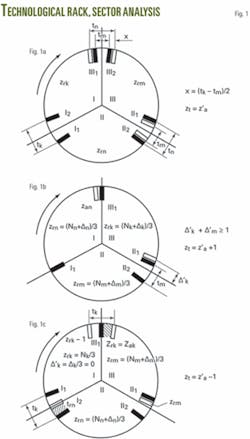
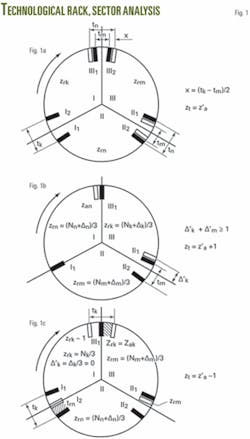
If, at the initial moment that the bottom-well rack is formed, all cones contact the hole bottom by two teeth, instead of one tooth, this case would not differ from the initially assumed case. This is because the difference in the cone kinematics would only be in the calculated numbers of the rack teeth, Nk + Δk, change for the value x/t. In other words, they will equal Nk + Δk + x/t, where x = (tm tk)/2, while even equal heel teeth pitch would not make much of a difference because x = 0 (Fig. 1a).
This means that if the cones begin to form the rack on the bottom of the hole, all of them supported by the same number of the heel teeth, then the rack will correspond to the “structural” type.
The moment the cones touch the well bottom with their heel rows, their second-row teeth also contact the well bottom (when spudding from a flat, horizontal surface, multicone bits may initially bear only against their second rows). Actually, at the initial moment of the well-bottom rack formation with the heel rows, each of the cones may arbitrarily bear against either one or two of the heel teeth. And that determines the character of the technological rack profile in each individual drilling episode.
If fractional parts of the estimated rack teeth number at two adjoining sectors (when considering a three-cone bit, each rack sector adjoins the other two) added up are equal or close to 1, (Δ’k + Δ’m = 1 or Δ’k + Δ’m ≈ 1 or Δ’k + Δ’m > 1) and if, at the beginning of the rack formation, one of the cones is supported by a single heel tooth while the other rotationally successive bit cone is supported by two teeth contacting the rock, then the actual technological rack teeth number will exceed that of the structural rack by 1, as shown in Fig. 1b.
If the estimated quantity of the teeth in some sector of the rack for the given cone is equal to an integer, i.e., zrk = zak = Nk/3 (at Δk≈0)or zrk, and if that cone at the beginning of the rack formation is supported by two contacting teeth while the other rotationally successive cones are supported by one and two teeth accordingly, then the actual number of the technological rack teeth will be less by one than that for the structural rack. This is because a half of the “tooth” from both sides of the considered sector will be twice subtracted from the value Zrk = Zak. Fig. 1c, which illustrates this, showing that from the sector of the cone I that has Zrk = Nk/3 and, at the beginning of the rack formation, is supported by two teeth, I2 and I1, one “tooth” with its two halves (Fig. 1c, shaded) behaves as if migrating into the adjoining sectors of the rack where the number of teeth has remained constant.
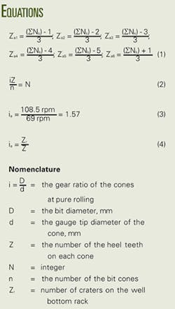
In the general case, to avoid a detailed analysis of all possible combinations of positions of the contacting teeth of the cones, the number of the basic technological rack versions for the given bit may be found formally using Equation 1 which can yield six values of the actual “teeth” number for the rack, Z’a. At that, the number of the basic versions will be determined by the quantity of integral Z’a values.
Commercial bit variation
Table 1 supplements the table on characteristics of commercial bits already published in Part 2 of this series (OGJ, Feb. 11, 2008, p. 42). The earlier table presents structural kinematic parameters of four different bits (B-151T, B-190T, K-190T, and K-214T). Table 1 records possible versions of the technological rack and their corresponding gear ratios, and notes the “leading” cones.
We see from Table 1 that each bit can form a well-bottom rack with different technological values for the teeth, Zt:
- B-151T bit can have three basic technological values for the teeth, Zt = 31, 32, and 33.
- B-190T bit can have two values, Zt = 29 and 30.
- K-190T bit can have three values, Zt = 28, 29, and 30.
- K-214 bit can have two values for the “teeth,” Zt = 28 and 29.
Taking into account the fractional values of Z’a that tend towards one or another value of Zt or which can constitute an additional Zt value leads to the conclusion that for each version of the rack there exists a different probability for its formation.
Table 2 shows the probabilities of rack formation at the given teeth number for the four commercial bits, P(Z).
Table 3 shows the most probable numbers of technological rack teeth and their corresponding technological gear ratios for the cones of the four bit types.
In most cases, the data in Table 3 reveal conformity of the technological and structural racks for the B-190T bit, while the B-151T, K-190T, and K-214T bits are more prone to form the technological rack with one less tooth than the number of teeth of the corresponding structural rack. This means that the cones of the latter three bits are subject to excess skidding.
Tooth migration
The data also indicate that the two similar bits, B-190T and K-190T, manufactured at different plants, vary in their kinematic parameters, as previously published.1
This difference reflects the fact that the estimated teeth number of one of the rack sectors for the B-151T, K-190T, and K-214T bits is equal to or very close to an integer, and that may result in migration of one of the rack teeth, which is not observed for the B-151T bit (OGJ, Feb. 11, 2008, p. 42; Table 1).
Moreover, the B-151T, K-190T, and K-214T bits exemplify a firm trend of this kind of tooth migration and therefore such correlation of the estimated rack teeth numbers should be avoided in bit design. In particular, the gauge tip diameter of the K-190T bit cones should not equal 125.59 mm, but should be 124 mm, as it is in the B-190T bit.
The difference in the B-190T and K-190T bit kinematics caused by a slight variance in the gauge tip diameters of their cones (only 1.59 mm) leads to different results in performance, as revealed during their stand tests1 and affirmed in field practice. It is well known that the efficiency of K-190T bits lags behind that of B-190T bits.
Bit efficiency
Hence, an important conclusion may be drawn that kinematics and consequently, the efficiency of rock bits, are very closely related to accuracy in their manufacturing and may vary, regardless of whether they are within design tolerances. It is not accidental that problems of bit manufacturing quality impact their performance and are subject to investigation.2
Besides this, the bit kinematic parameters will vary due to wear of the gauging sides of the cones during drilling. In particular, skidding of the cones’ heel rows will progress, making their wear even more pronounced. It’s obviously necessary to solve the problem of bit gauge loss while drilling with milled-teeth drillbits.
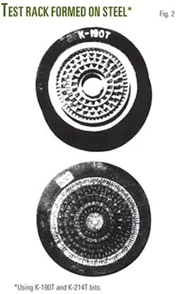
Fig. 2 shows the character of the rack formed by the K-190T and K-214T bits when drilling steel hole bottom on a test drill stand at the Kuibishev specialized bit design office in Russia. Comparing these pictures with a previously published image (OGJ, Feb. 4, 2008, p. 46; Fig. 3), which shows the hole bottom formed by the B-190T bit, we see unambiguous confirmation of the substantial difference in kinematics of the bits.
If the rack formed by the B-190T bit is clear-cut and even along the entire metallic bottom, then the bottoms formed by the K-190T and K-214T bits lack the rack rolled by the heel and central rows due to their excessive skidding. Consequently, the B-190T bit destroys the whole surface of the hole bottom with equal efficiency while the K-190T and K-214T bits just hang up on the second rows of their cones.
For the K-190T and K-214T bits, the increased skidding of the heel and central rows does not promote a higher rate of well-bottom destruction and results in excess wear. Simultaneously, the bit bearing is subject to a more intensive wear since the increased skidding of the cones predetermines their increased torque. It is well known that during cone rotation, the moment of rock resistance is equal to the moment of frictional forces in the bearing. This explains the fact that during drilling in field conditions both the cutting structure and the bearing of the K-190T bits are, as a rule, less wear-resistant than those of the B-190T bits.
Cone arrangement
It’s important to note some other peculiarities of the rock bit kinematics.
Mating of the peripheries of the well-bottom sectors is accompanied by rearrangement of the rack teeth at points of major skidding of the cones with their completing teeth. Unsteady cone rotation may be observed at the onset of drilling, manifested as a variation of cone gear ratios due to possible deviation of the character of the formed rack from its technological profile. This especially applies to rock formations of reduced hardness where the rack is less stable than in hard rock.
Moreover, since the character of the rack profile, as stated above, is influenced by the interrelated distribution of the contacting teeth of the cones at the beginning of formation of the well bottom, the rack profile will also depend upon the order in which the bit cones are assembled (direct or reverse).
The direct order is a clockwise arrangement of cones I, II, and III as observed from the well bottom. The reverse order has a counterclockwise arrangement. The change in cone arrangement alters the order of mating of the rack sectors and may affect the technological rack teeth number.
Besides, the bit kinematics will be influenced by the interrelated distribution of the cones with maximum and minimal pitch of their heel rows. If the cone with tmax follows directly after the cone with tmin, then during drilling in rock of reduced hardness, the cone with tmax, when moving in the sector that has been rolled by the cone with tmin, may slow down instead of accelerating (as discussed in Part 1).
However, if during the bit rotation, the sector formed by the cone with tmin is first entered by the cone with medium pitch and followed by the cone with tmax, provided that the cone with medium pitch, due to minor difference between tmed and tmin, will be capable of accelerated rotation, then, having broadened and deepened the craters in the sector with tmin, it also promotes favorable conditions for accelerated rotation of the cone with tmax.
Of course, the absolute pitch sizes of the heel teeth will affect the size of ridges between the rack craters, depending upon the bit’s diameter and type. Naturally, the smaller the pitch size, the higher the probability of the ridges shifting (according to Part 1). Then, during drilling of softer rock, the cone with tmax will be more prone to slowed rotation, rather than acceleration.
Consequently, a seemingly insignificant factor, such as the order of the cone arrangement in the bit, may affect the bit performance and its durability.
Rock surface effect
The character of the technological rack profile is also influenced by the condition of the rock surface during spudding of the well. This is significant in both test-stand conditions and real well drilling.
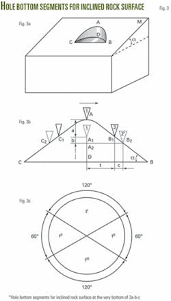
If the rock surface is not horizontal, which is typical for many test-stand drilling setups with natural stone blocks, then at the beginning of drilling, the bit will create some part of the future hole bottom in the form of a segment that will gradually enlarge as the bit deepens to full circle. At first, axial load on the hole bottom will be transferred through one of the cones. Then, two cones will simultaneously contact the rock and, at last, the bit will be supported by the three cones at the full hole bottom.
The diagram in Fig. 3a shows the hole bottom segment CDB during spudding from the surface M having inclination, α. CAB is the line intersecting the inclined surface M and the part of the wall of the intended hole. The schematic in Fig. 3b shows the developed views of the arc for the segment CDB in the form of a straight line and an elliptical arc CAB in the form of two semiarcs: the descending AB and the ascending CA.
If the spud surface was horizontal, the hole bottom rack formed by the heel rows in the section CDB would have the pitch, t, corresponding to the heel teeth pitch of one of the three cones which had initial contact.
During actual spudding, the teeth of this cone move along the descending section AB in the direction of the cone rotation shown by the arrow. Consequently, Tooth 2, due to the rearrangement of its loading will slip along the inclined plane at slowed B1B2, which will be confined by translational movement of the bit equal to b = A1A2. The movement of the bit while deepening a = AA1, corresponds to the moment of Tooth 2 touching the inclined plane and will depend upon the cone number simultaneously contacting the well-bottom segment and the value of the axial load. Due to Tooth 2 slippage, the well-bottom rack pitch increases for the value c = b·ctgα and will be equal to t’ = tk + c = tk + b·ctgα.
A similar picture will be observed on the side of the ascending section CA, the only difference being that the teeth will slip along the inclined plane and accelerate.
Thus, spudding from an inclined surface will result in rolling the sector of the rack with pitch t’, and then, when two cones contact the well-bottom segment, the rack pitch on both sides of the segment will slightly decrease due to the decreased translational movement of the bit (at constant axial load) and will have the value t’’, which will decrease once more, to a value t’’’, when all the three cones come into contact with the well bottom.
Pitch size
Finally, the well-bottom rack will again have three different pitch sizes that will be distributed in four sectors, as shown in Fig. 3c, at the following correlation of their values: t’ > t’’ > t’’’. All three values, t’, t’’, and t’’’, may be higher than the calculated values of the rack pitch, tk, even if spudding was started by the cone with minimum pitch of the heel teeth.
The difference between t’, t’’, t’’’, and tk may be regulated by the axial load. At a high axial load t’>t’’>t’’’>tk, while at a low axial load t’ ≈ t’’ ≈ t’’’ ≈ tk. However, even in the latter case, the number of the teeth in the technological rack may vary when compared with the rack that would be formed during spudding from a horizontal surface, due to the disturbance of the strict periodicity of the three rack sectors.
Thus, during spudding from inclined surface, a common trend of increase in the rack pitch appears, i.e., the number of the rack “teeth” decreases. This inevitably results in increased skidding of the cones and their intensive wear.
A similar result can be expected during spudding on a surface with varying roughness.
Drilling conditions
Under actual drilling conditions, the lithological profile usually consists of alternating rock types with varying hardness that may dip at different bedding angles. Consequently, when the drill bit encounters a layer of harder rock during drilling, the situation will be similar to that of spudding on an inclined block surface, and the rack teeth number will decrease.
When a bit encounters a softer formation, the rack profile may also change. Clearly, the well-bottom rack profile does not remain stable during drilling but changes according to the lithologic sequence encountered. The bit kinematics will vary.
This explains the significant scatter in drilling performance data for commercial rock bits when they are run in “identical” conditions in actual wells. Peculiarities of bit kinematics for each run will be diverse. This is also the reason for observed variations in the character of the bit wear during drilling in test stand and actual conditions, and of the wide versatility of the bit wear types in deep well drilling.
The last factor affecting the profile of the technological rack implies the bit tearing off the well bottom during drilling, followed by an abrupt increase in the weight on bit. This may involve considerable chattering of the bottomhole assembly. Torn off the well bottom, the teeth may arbitrarily hit the rack, partially destroy it, and create another set of teeth.
Relief stripes
On the sides or walls of the well, we see relief stripes related to the well-bottom rack problem.
Multiple-pitch cones, as a rule, provide for heel teeth slippage accompanied by widening of the rack craters in one or more directions and at each revolution of the bit, the rack profile will gradually shift in plane. The direction of the rack shift will depend upon the correlation between the values and directions of skidding of the different cones.
Since the cone movement is for the most part slowed, the rack profile shift will generally be directed opposite the bit rotation. However, the rack profile may still shift in the direction of the bit rotation. This can be determined by correlating the technological gear ratios of the cones at any point during drilling. The rack shifting behavior will match the inclination of the relief stripes on the well wall.
In the case of equally pitched cones, the well-bottom rack may wander and the relief stripes may vary in inclination.
Pure rolling
The analytical study of drill bit kinematics which was discussed in Part 1 permits us to conclude that duirng design of toothed rock bits it is possible to select geometric parameters of cones that will provide minimal teeth skidding along the well bottom (OGJ, Feb. 4, 2008, p. 46). The actual gear ratio of the cones should correspond to pure rolling.
In the case of multicone cutter bits, pure rolling would be peculiar only to heel rows. In the single-cone cutter bit design pure rolling would occur for all rows. Such cone design is especially important for milled-tooth bits because it can substantially increase their wear resistance and efficiency during drilling of abrasive rock.3
Corresponding to this condition are cones with equal pitch of their heel teeth; these may be determined by the correlation4 shown in Equation 2.
Thus, for the B-151T bit, which has the value i = 1.57, the actual cone gear ratio would be close to pure rolling at Z = 21, corresponding to the teeth pitch t = 14.3 mm (OGJ, Feb. 4, 2008, p. 46, Table 2).
Experimental bits
To verify this idea, the Verkhneserginsky bit plant manufactured several experimental bits. Based on the commercial B-151T multicone cutter bit, the experimental cone bits with equally pitched heel rows included the 21B-151T bit with heel tooth number Z = 21, and the 20B-151T bit with heel tooth number Z = 20.
The 20B-151T bits were built to verify the conclusion stated in Part 1, which considered that if all bit cones had even number of equally pitched heel teeth, then their actual gear ratio tended to equal 1.5 (OGJ, Feb. 4, 2008, p. 46).
The experimental 21B-151T and 20B-151T bits as well as the commercial B-151T bit were tested on a drill stand in quartzite with WOB of 4.6 tonnes and 8 tonnes. The rotational speed of the drill stand spindle was 69 rpm. The borehole was flushed with water.5
The bits were equipped with variable-induction pickup that recorded the rotation rate of each cone while drilling by means of a light-beam oscillograph.
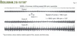
The oscillograph in Fig. 4 shows the rotation speed for the 21B-151T bit and its first, second, and third cones (from top to bottom).
The figure shows that the rotational speed of each of the cones is 108.5 rpm, irrespective of the weight on bit. Consequently, Equation 3 shows the actual gear ratio for each cone, and it corresponds to pure rolling mode of the cone heel rows.
The actual gear ratio of the cones was calculated based on the number of craters on the well-bottom rack, Zr, as shown in Equation 4.
During drilling with the 21B-151T bit, the number of craters on the well-bottom rack, Zr = 33, corresponds to a gear ratio, ia = 1.57.
But during drilling with the 20B-151T bit, the well-bottom rack had 30 craters. Consequently, the gear ratio is ia = 1.5, which neatly corresponds to the analytical results.
Rock destruction
In addition to studying experimental bit kinematics, it was interesting to investigate the rock-destroying capability of the bits, their wear characteristics, and performance efficiency.
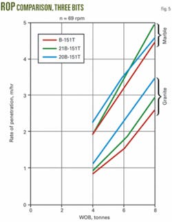
The rock-destroying capability of the experimental bits as compared to that of the commercial bits was studied during drilling in marble and granite with a WOB of 4.6 tonnes and 8 tonnes and a bit rotational speed of 69 rpm.
Fig. 5 plots the varying, initial ROP of the experimental bits vs. WOB duirng drilling in marble and granite. The data confirm that the experimental bits with equally pitched heel rows of the cones have better rock-destruction capability compared with the commercial bits when drilling in medium-hard and hard rock.
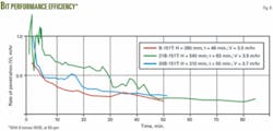
We also studied the performance efficiency of the bits while running them to wear in quartzite with WOB of 8 tonnes at 69 rpm. The time plot of the drilling-rate decrease for the experimental and commercial bits shows the superiority of the 21B-151T bits performance and wear resistance (Fig. 6). The mean meterage per 21B-151T bit was 540 mm at the mean rate of penetration of 3.9 m/hr. For the commercial bits, the meterage per bit was quite a bit less, only 280 mm at 3.5 m/hr.
Bit wear
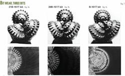
Fig. 7 shows the wear and hole-bottom patterns of the 21B-151T, 20B-151T, and B-151T bits. A comparison of these drawings shows that the heel teeth of the 21B-151T bits have considerably less wear, despite drilling nearly twice as far as the commercial B-151T bits.
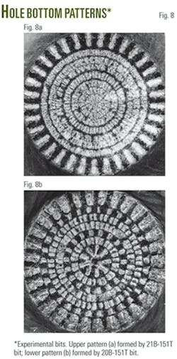
Fig. 8 presents the hole bottom patterns formed by the experimental 21B-151T (Fig. 8a) and 20B-151T bits (Fig. 8b). These patterns illustrate the clear-cut peripheral rack formed by the 21B-151T bit, which visually confirms the lack of any skidding of the heel rows along the hole bottom, in contrast to the skidding seen with the 20B-151T bit. This once again confirms that the equality of the cone heel teeth numbers is necessary but not a sufficient condition to reduce their skidding.
Equal heel teeth numbers on the cones provide only their equal skidding, which may be rather high. As a result, the performance and wear data for the bits with equally pitched heel teeth on their cones may even lag behind the bits having different cone-heel teeth numbers.
References
- Simonov, V.V., Brevdo, G.D., and Yegorov, A.E., “Comparative test-stand study of the 190-mm bit performance,” Moscow: Transactions of the I.M. Gubkin Institute of Petrochemical and Gas Industry, Issue 96, 1970.
- Pozdnyakov, V.I., Study of impact of the rock bit manufacturing quality on drilling performance. PhD thesis, Moscow: Research Institute of Drilling Engineering (VNIIBT), 1970.
- Palaschenko, Y.A., “Research of drilling with roller bits destructing the well bottom in the mode of pure rolling of the cones,” Drilling technology of oil and gas wells, Moscow: Transactions of the I.M. Gubkin Institute of Petrochemical and Gas Industry, Issue 152, 1980.
- Palaschenko, Y.A., Simonov, V.V., Drilling roller bit, Russia Patent No. 933932, Cl. E21B 10/16, 1982.
- Palaschenko, Y.A., “Tricones a parametres cinematiques optimums,” Paris: Forages, No.134, 1992.
