Geothermal sources for direct heating can theoretically serve as an alternative source of high-temperature (>130° C.) heat in processing plants.
Cutting CO2 emissions from a refinery requires reducing the amount of fuel burned. Although CO2 savings was the motivating and initial goal of this study, the real economic incentive is savings in refinery fuel burned. We estimated this at roughly 6 times the value of CO2 emissions saved based on $15/ton CO2 and $68/bbl of crude.
The upper sedimentary layer in the West Netherlands basin is not thermally or geomechanically interesting for creating a geothermal heat exchanger; however, the underlying deformed sediment layer and expected depth to basement of 8-10 km are favorable for the required temperatures, fracturing, and drilling prospects.
Considerable savings are possible if low-enthalpy waste water was injected for geothermal recovery. This makes most efficient use for obtaining high-quality heat, as compared to a previous EOR water-flooding proposal.
The combination of favorable geothermal gradient, large petrochemical plant or refinery, and the subsurface uncertainties means that the risks are considerable although the rewards are potentially high. The proposed scheme thus requires considerable research and development before it is an economically viable process.
Geothermal energy
Heat obtained from geothermal energy is more efficiently used for directly powering petrochemical and refining processes rather than for electricity generation. Significant reductions in CO2 emissions from burning fuel are possible. The savings, however, from not burning refinery fuel are even greater.
If refinery waste water is injected, then the subsurface geothermal heat exchanger fracture network is more efficient.
The relatively low temperatures that are obtained and, therefore, the low efficiency thermal-to-electric energy conversion hampers use of geothermal energy for electricity generation.1 Recently, a study proposed using EOR flooding water (OGJ, Sept. 5, 2005, p. 34) to generate electrical power. The process is still relatively inefficient. It is more efficient to use this water directly to power chemical conversion processes because this can reduce fuel burned.
Such a direct integration of an upstream and downstream process has not, to our knowledge, been proposed within the oil and gas industry. One can remove the inefficiencies associated with electricity generation by applying the heat obtained from geothermal operations directly to downstream oil and gas processing on a refinery scale.
CO2 reduction
To reduce CO2 emissions from a refinery means reducing hydrocarbons burned.2 Biofuels, for example, is a step in this direction because its cultivation involves CO2 as feedstock, as does subsurface sequestration of CO2 in reservoirs. Closely related is the use of biomass, which is defined as carbon neutral. Both reduce CO2 on a well-to-wheel basis, unless sequestration is used to offset heavier feedstocks like tar sands.
Other than these developing but nonetheless combustion-oriented, and therefore CO2-producing, processes there are basically three reliable direct-heat options for producing the hot steam needed for refinery processes:
- Nuclear energy. Nuclear fission directly heats water to make superheated steam.
- Wind power. Turbines generate electricity, which then powers coil heaters.
- Geothermal power. Subsurface hot water directly powers processes.
Nuclear power is probably an unacceptable option for local refinery heating plantsit is better for electricity generation. Wind power is not necessarily reliable and is relatively inefficient due to limits on turbine generation of electricity that is then turned back into thermal energy. For both of these, hydrogen generation is an attractive route because it can be stored.
The advantage of geothermal heat over concentrated solar panels or photovoltaic is the continuous flow of energy; solar energy is not constant and would not be an option for a large number of refineries in, for example, Northern Europe.
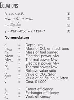
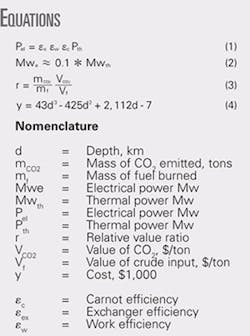
The same problem applies to the use of geothermal power to generate electricity. In that case, the electrical power is related to the thermal power using Equation 1 (see equation box). Equation 1 represents the products of the heat exchange, work, and Carnot efficiencies.
This means that the geothermal water stream and the organic working fluid, which mechanically drives the turbines, must exchange heat. This further reduces efficiencyheat exchangers, secondary power fluids, and various other intervening steps mean that typically only 10% of the thermal power (250º C.) ends up as electrical power (Equation 2).
This restriction would not of course apply if only thermal power is needed. The 90% losses could still be used for running chemical conversions. It is much better to use the energy directly in its naturally generated form, i.e., thermal heat. Geothermal power is therefore an option because of its ability to generate superheated steam directly.
The problem is that many geothermal projects generate contaminated water, which is low-quality energy (low temperature). Most operations in the Netherlands, for example, are relatively shallow (<3 km) and only provide water up to about 100º C.3 This was exactly the restriction identified in the EOR study; the authors stated that the inefficiency was reduced because the water was already available following removal of the oil after flooding production.Refineries already have much low-energy water available, but it is all low-quality heat, typically <130º C. Because a refinery needs higher-grade (hotter) energy, our study tried to determine how much process heat, and thus fuel burning and CO2, this would save if sufficiently hot (130° C.) water could be generated.
Process heat
Clearly, more than one geothermal producer well is required for a refinery, and the configuration will affect the economics. The following issues must be addressed:
- Is the necessary thermal energy flux available to directly heat units in a refinery and what will be the cost?
- What temperature will give what CO2 savings?
- What is the cost associated with drilling to a depth to reach that temperature?
The first thing we did was estimate the heat flux required. In this case it is not just the temperature, but also the amount of energy required.
We started by imposing the most difficult conditionwe only wanted heat above 130º C. We assumed that internal refinery heat integration would provide enough process water for up to that temperature.
Waste heat, which is abundantly available at refineries, can therefore be recovered to provide the preliminary process unit heating to 130° C. This is the starting temperature at which either traditional combustion heat or geothermal heat will come into play for reaching the required process temperature. For atmospheric distillation, 340° C. is typically reached with superheated steam.
These considerations typically apply for large refineries (50,000 tons/day of crude processed) where a significant fraction (5-10%) of hydrocarbon intake is required to fuel the processes themselves. We assumed that an average of 8% of the equivalent hydrocarbon intake is actually burned to power the distillation, conversion, and treating processes (including hydrogen manufacture). The required heat fluxes, temperatures, and related mass flows form a complex system and a detailed analysis is beyond the scope of this initial study.
We started with the crude distillation unit, through which all the crude feed passes, and which usually consumes about ¼ of the heat flux. Typical heat fluxes for distilling 50,000 tons/day of crude are about 500 Mwth, which is about 2% of the hydrocarbon intake (either as refinery fuel gas or fuel oil) for processing. The maximum temperature required is about 340° C.
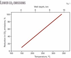
Geothermal heating to 340° C. therefore obviates the need for combustion heat (100% CO2 emissions avoided) in the crude distillation unit and geothermal temperatures less than 130° C. are not required (corresponding to no savings in combustion CO2). Because 2% of the fuel intake is burned, this immediately indicates the amount of CO2 produced. Accordingly, we can calculate the reduction in CO2 emissions as a function of the geothermal heat source temperature.
Fig. 1 shows the percentage savings in CO2 emissions as a function of the temperature of the hot water that can be obtained. The upper axis shows the corresponding drill depth typically reached.
A geothermal source at 190° C. would therefore cut CO2 emissions by about 30%. This was the initial target of this study; however, a cursory examination shows that much larger financial savings come from significant reductions in fuel combustion for providing process heat. We therefore considered the relative values of CO2 saved and the mass of fuel burned and their associated values.
In Equation 3, r is the relative value ratio of CO2 saved and fuel input burned.
The first term is the ratio of masses of CO2 to refinery fuel burned. To a first approximation, this ratio is independent of the fuel’s molecular weight; it is purely dependent on the ratio of CO2 to carbon and hydrogen molecular weight (represented by CH2). For any except the lightest molecular-weight fuels, the ratio converges to 3.1; i.e., it does not make any difference if it is a heavy refinery fuel or a lighter feedstock.
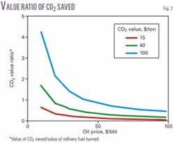
The more volatile portion of Equation 3 is the second multiplierthe relative value ratio. Until recently, common values were CO2 at $15/ton and crude at $68/bbl. For a typical crude (specific gravity of 0.85), this gives a ratio value of about 0.1, which means that the value of fuel saved is 10 times that of the CO2 saved. Although CO2 emissions are reduced, the real economic savings come from not having to burn fuel. Total savings is the sum of the numerator and denominator.
The magnitude by which the fuel saved exceeds the value of CO2 is geographically dependent and only gradually is a consensus emerging for this.
Fig. 2 shows how the ratio of CO2 to refinery fuel value changes with oil price for different CO2 values. CO2 values range from a standard $15/ton to the high values maintained in countries like Norway. Assuming that 1 bbl of oil roughly yields 0.4 tons of CO2, in a high CO2-tariff ($50/ton) country like Norway, if the oil price is $50/bbl, then the associated CO2 penalty is $20, which is 40% of the value of the crude.
There are some scenarios in which the value of CO2 saved exceeds fuel savings. Given higher crude prices, all except the most extreme CO2 valuations mean that the refinery fuel savings is the main motivation for using external geothermal to power refinery processes.
Geothermal heat flux
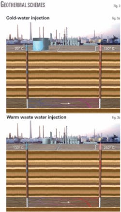
The simplest way to mine geothermal energy is to produce hot formation water from deep water-bearing layers. In most cases, water must be injected from the surface. In the local refinery case, using available waste hot water rather than cold water leads to considerable savings.
We compared the two scenarios:
- Cold-water injection (Fig. 3a). Much of the subsurface heat is used to heat ambient water to 130° C. before obtaining quality heat above this temperature. This results in unnecessary geothermal source depletion (drawdown) because high-quality heat is lost to low-quality enthalpy in the water.
- Waste water at temperatures approaching 130° C. (Fig. 3b). These energy savings and the associated value, although significant, are still small compared to the savings in burned fuel.
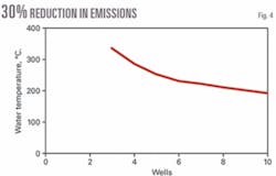
Under an assumption that hot water is available to meet the temperature requirement, the amount of water needed is about 500 kg/sec. A modest estimate is 50 kg/sec/well. The EOR study used projected flows of 50-250 kg/sec, which are rather high. Two options are to drill a few deep wells and obtain high-temperature water or drill more numerous shallower wells (Fig. 4).
Although configurations of one injection well and multiple production wells have been considered, a more realistic scenario is two production wells fed by one injection well (triplet option). Because we assume this case, only even numbers of producer wells should be considered in Fig. 3, which is based on each well producing 50 kg/sec of fluid with total power of 130 Mw.
Hot rock
The remaining question is the cost associated with drilling to the required depth. We have been using a generic refinery in this study. We must therefore consider the local geology underneath a refinery.
First, we must consider where the heat lies and examine the thermal gradients. Then we must assess the geological problems for accessing the heat. This depends on refinery location.
The EOR study pointed out that, although production operations are often where thermal gradients are relatively unfavorable, well drilling and pumping costs are already covered by oil production. Even if the temperature is relatively low, it is basically available for free.
Ideally the refinery is next to a production operation in which EOR is practiced with high water cuts being produced. Even without this situation, however, we can outline many requirements about the depth of wells required for direct heating of a refinery.
The EOR study used locations in Texas and Arkansas. In this study, we selected the West Netherlands basin. This region has a high manufacturing process intensity and therefore demand for process heat. It also has significant onshore and offshore gas production and therefore deeper wells.
The Earth’s average thermal gradient is 30° C./km. There is evidence that this gradient is higher in the West Netherlands Basin and Roer Valley. Temperature profile maps indicate that depths of more than 4 km are required.4 To assess the cost of drilling these wells, we examined the geology of layers deeper than 4 km.
From studies of geothermal gradients in the Roer Valley Graben, we derived the depth of drilling required to yield a particular savings in CO2 (Fig. 1).4 5 Ideally, we would drill as deeply as possible. We therefore considered drilling below the level normally associated with hydrocarbon deposits but still above the basement rock, which is usually associated with geothermal studies.
Access
In geothermal drilling, the aim is to reach hot granite in the basement typically 4-5 km below the surface. The West Netherlands, however, has an unusually thick layer of sedimentary rock. The actual depth to the metamorphic basement is unknown, but the upper sedimentary layer is characterized as principally Permian and younger sandstone.6 7
This layer is not interesting because the temperature is too low. Below 4 km there is still a considerable depth of sedimentary rock. This has a different character in that it is deformed and consists mainly of carbonate.
The top of the crystalline basement of the West Netherlands probably lies at 8 km, but its precise position beneath the sedimentary succession is unknown.7 8 The thickness of the upper nondeformed sandstone sedimentary layer is about 4 km. We therefore estimate the lower deformed sedimentary carbonate at about 4-km thick.
For heat-recovery purposes we focus on these deeper deformed carbonates. These folded, faulted, and fractured carbonate rocks are the target for drilling geothermal wells and represent many opportunities that have not been investigated. They might have pre-existing fracture networks that can be used for circulating between wells.
The main costs associated with geothermal programs are drilling, but we are considering pre-existing oil production facilities. It is, however, easy to drill through sedimentary rock. The sandstone and underlying carbonates in the West Netherlands basin have much higher permeabilities than the sedimentary layer above traditional geothermal operations. This leads to higher rates of penetration that will reduce drilling costs.
Although granite has a very low permeability, the candidate sedimentary region we have identified has a higher permeability than granite. The undeformed sedimentary layer on top is principally sandstone, which shows decreasing permeability with depth. The underlying deformed sediment, however, consists mostly of fractured carbonates with a higher porosity and should be easier to drill.
We compared the extra cost of drilling fewer wells to a greater depth with the costs of more shallow wells. A recent study provides an estimate of well costs using a polynomial (Equation 4).9
When we combine this with the number of wells required (Fig. 3) and the corresponding depths from Fig. 1, there is a slight decrease in well costs, to 6 from 4, but after that it gets rapidly more expensive.
Estimated well cost is $70 million. Assuming the normal 25 years life with a 25% operational cost add-on we obtain $3.1/Mwth-hr.
This compares favorably with classic combustion-generated heating. The cost of refinery fuel is typically about 10% of the oil price ($68/bbl) so that current combustion-based heating costs are around $3.7/Mwth-hr.
There are therefore too many uncertainties to make a clear-cut basis for applying geothermal heat for refinery power. Oil prices would have to be stable at higher prices to justify wholesale refinery plant modifications.
References
- Kutsov, I.M., “Applied geothermics for petroleum engineers,” Amsterdam: Elsevier, 1999.
- Walters, L., Wade, D., and Lewis, D., “Transition to a nuclear/hydrogen energy system,” Nuc. Ener., Vol. 42 (2003), No. 1, pp. 55-62.
- Dufour, F.C., “Country update for the Netherlands,” Geothermal Resources Council 1990 Annual Meeting, Davis, Calif., pp. 203-204.
- Hurtig, E., Cermak, V., Haenel, R., and Zui, V., eds., “Geothermal Atlas of Europe,” Potsdam, Germany: GeoForschungs Zentrum, 1992.
- Remmelts, G., and Duin, E.J.Th., “Results of a regional deep seismic survey in the Netherlands,” The potential of deep seismic profiling for hydrocarbon exploration, Paris: Editions Technip, 1990, pp. 335-43.
- Frost, R.T.C., Fitch, F.J., and Miller, J.A., “The age and nature of the crystalline basement of the North Sea Basin,” Petroleum Geology of the Continental Shelf on North-West Europe, London: Institue of Physics, 1980; pp. 43-57.
- Ziegler, P.A., 1981, “Evolution of sedimentary basins in North-West Europe,” London: Institute of Physics, 1981.
- Pharoah, T.C., “Palaeozoic terranes and their lithospheric boundaries within the Trans-European Suture Zone: a review,” Tectonophysics, Vol. 314 (1990), pp. 17-41.
- Bloomfield, K.K., and Laney, P.T., “Estimating well costs for enhanced geothermal systems applications,” US Department of Energy Report INL/EXT-05-00660, 2005.
The authors
Mike Golombok ([email protected]) is a principal scientist with Shell Exploration & Production, Rijswijk, Netherlands. He has previously worked in downstream research for Shell, researching fuel combustion, gasoline component manufacture, and steam cracking. Golombok holds a BSc from the University of Glasgow and a PhD from the University of Toronto. He is a part-time professor of mechanical engineering at Technische Universiteit Eindhoven where he holds the chair of Oil and Gas Production Technology.
Kike Beintema is a structural geologist with Shell Exploration & Production, Rijswijk, Netherlands. She has previously worked on sour gas sequestration and is currently working on fractured reservoir characterization and modeling of carbonates. Beintema holds an MSc in structural geology and materials science from University of Utrecht. She received her PhD from University of Utrecht on the subject of Archaean plate tectonic processes.
