CLASSIC BIT KINEMATICS—2: True kinematics opens way to bit improvement
In the first part of this series, published last week (OGJ, Feb. 4, 2008, p. 46), we began to show how roller cone bit design analysis can predict cone behavior, with heel teeth having equal pitch.
This second of four articles presents how bit kinematics are modeled differently when the heel teeth on all roller cones have varied pitch.
In this case, after completing a third of the bit revolution, the well-bottom rack will consist of three sectors, each sector resulting from the interaction of the corresponding cone with the well bottom and having its own, individual profile. The further rolling of the well-bottom rack during bit rotation will be determined by this initial profile, which sets the total number of rack “teeth” with variable pitch that changes every other 120º.
Parts three and four will follow in weeks to come.
120º rotation
Let’s calculate the rack “teeth” number when the bit turns a third of its revolution (120º). Each of the three cones will roll its own individual estimated “teeth” number:
Zr1 = (N1 + Δ1)/3, Zr2 = (N2 + Δ2)/3, and Zr3 = (N3 + Δ3)/3, where N1+ Δ1, N2 + Δ2, and N3 + Δ3 are the estimated number of rack “teeth” that can be imprinted on the well bottom by the given cone per bit revolution. This assumes that the two other cones do not take part in forming the rack, i.e., Nk + Δk = i·Zk, and Zrk = (Nk + Δk)/3 = N’k + Δ’k.
Click here to view the Equations in PDF format.
The total estimated number of the well-bottom rack “teeth” after the bit turn for a 120º revolution is shown in Equation 1. Assuming that Zr1 = (πD)/3t1, Zr2 = (πD)/3t2, and Zr3 = (πD)/3t3, where t1 ≠ t2 ≠ t3, we may write this as Equation 2.
By analogy with the previous section, let’s determine the boundaries for the actual number of the rack teeth, Z’a.
Note that Z’a = ΣZak, and in the general case, the number of Za values will be determined by combinations of 3 out of 12, i.e.,C312 = 220.
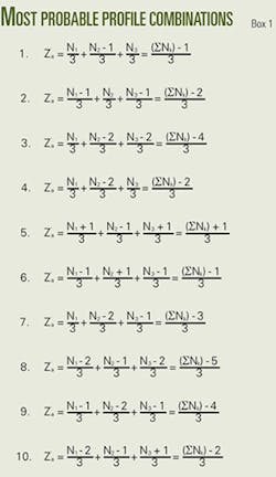
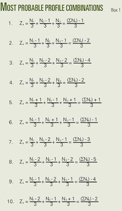
Analyzing the data presented in the two tables in Part 1 (OGJ, Feb. 4, 2008, p. 46) and taking into account that the number of teeth on the cone heel rows of commercial bits usually corresponds to three successive numbers, we may find the 10 most probable profile combinations of individual sections of the well-bottom rack, as shown in Box 1.
These equations show that the actual number of the rack “teeth” when drilling with the commercial three-cone bits may finally have six values, as shown in Equation 7.
Leading cone
Having determined the value Z’a, let’s compare it with the values Nk + Δk for each of the cones. Equal or nearly equal Z’a and Nk + Δk values point to the so-called “leading” cone. If, for the leading cone, Nk + Δk = Z’a, then iak = i, as i = (Nk + Δk)/Zk and iak = Z’a/Zk.
If the leading cone has Nk + ΔkThe term “leading” cone and the technique used to calculate the cone skidding rate were introduced in technical literature nearly 50 years ago. A commonly held opinion is that during use of a three-cone bit, the bottom-well rack is formed by a leading cone that controls the motion and cutting of the other cones.1
The lead cone is usually the one that rolls over the well bottom almost without skidding2 or the one with the least number of the teeth on the heel row.3 This choice of leading cone is made without ascertaining the real nature of its destination2 3 or based upon the assumption that the heel row teeth with maximum pitch display the highest kinetic energy and, consequently, they should form the deeper rack.4
Such assumption can hardly be admitted because the difference between the maximum and minimum pitch of the bit cone heel teeth is only 2-3 mm and therefore the difference cannot, to any significant extent, affect the value of the kinetic energy of the teeth.
In addition, even if there exists some difference in the kinetic energy of the teeth, the intensity of the grinding, and the depth of the bottom rack craters will be determined by the cone with the lowest kinetic energy.
Alternative choice
Due to insufficient validation of this assumption, as revealed by many experiments in which the cone rotational speed was recorded at Moscow’s I.M. Gubkin Institute of Petrochemical and Gas Industry, it is sometimes necessary to choose as the leading cone the one that has the next-to-largest size pitch of the heel teeth.4
Explaining the transformation of the leading cone features is based on the assumption that it is valid for cases when the length of the heel row teeth with maximum pitch is less than the length of the teeth of the other two heel rows, while the rack craters, shortened in their length, impede slippage of teeth of the other cone rows into them.
However, this assumption also contradicts the hypothesis concerning maximum kinetic energy of the leading cone row. In this case, strictly speaking, there should be two cones rolling over the well bottom almost without any skidding: the one with the largest heel teeth pitch (as nothing impedes the cone teeth slippage into the formed craters) and the cone with the second-largest pitch of the heel teeth.
The second cone would be the lead for the third cone while formally it would result in two leading cones, but that does not correspond either to theory or experiment. Consequently, it is reasonable to assert that the shortened length of the crater does not impede the teeth skidding because of the additional destruction that enlarges the crater. It is unlikely that a tooth capable of forming a crater might not partially destroy a crater weakened from residual stresses and strains.
Actually, the reason for the “leading” features displayed by one or another cone is seen by comparing the estimated number of the rack teeth for a 120º rotation with the estimated number of teeth for the same rack which might be individually formed by each of the three cones per revolution of the bit, i.e., Nk + Δk.
One of the three cones is able to roll a rack with the number of teeth closest to Z’a and therefore the apparent skidding of this cone per revolution of the bit will be minimal. This, however, does not mean that the given cone is the leading one. The racks that can be rolled individually by the other two cones may have fewer or more teeth, as compared with the actual well-bottom rack, and depending upon that, the rotation of the cones will either accelerate or decelerate. Which of the cones is the lead depends upon the actual number of teeth on the rack, Z’a.
But according to Equation 7, since Z’a may have six values, the minimum will be equal to Z’a min = Z’a5 = ((ΣNk)5)/3; the maximum to: Z’a max = Z’a6 = ((ΣNk) +1)/3.
Arithmetic mean
The feature that points to the “leading” cone implies the condition Nk + Δk = Z’a or Nk + Δk ≈ Z’a. If Za equals the arithmetic mean, i.e., Z’a = (ΣNk)/3, then the leading cone would always be that with the intermediate (mean) pitch of the heel row or, in other words, the cone with the second-largest pitch of heel teeth.
But since in five out of the six cases, the value of Z’a is less than the arithmetic mean by 1/3, 2/3, 1, 4/3, and 5/3, then, at least in four cases (at Z’a2 = ((ΣNk) 2)/3; Z’a3 = ((ΣNk) 3)/3; Z’a4 = ((ΣNk) 4)/3; and Z’a5 = ((ΣNk) 5)/3), the leading cone becomes the one with the lowest estimated number of rack teeth, Nk + Δk, i.e., the cone with the maximum heel teeth pitch.
At Z’a = ((ΣNk) 1)/3, the “leading” cone may be the one that has the maximum heel teeth pitch or that with the mean pitch size, depending upon which of them corresponds to the Nk + Δk value closest to Z’a.
At Z’a max = Z’a6 = ((ΣNk) +1)/3, the “leading” role will always be taken by the cone with the mean value of the heel teeth pitch.
Consequently, the most probable candidate for the “leading” role is the cone with the maximum heel teeth pitch size. The cone with minimum heel teeth pitch size may never be the lead. It will always rotate at a slowing speed.
Here, it needs to be emphasized that for a single bit, depending upon the number of the rack teeth, Z’a, formed in the given conditions (which may vary, as shown later), the leading role will be taken by the cone with either maximum or medium heel teeth pitch. Besides, change in Z’a value may result in transformation of the “leading” cone, i.e., for one Z’a value the “leading” role may be taken, e.g., by the first cone while for another Z’a value the “leading” role may be taken by the second cone, or vice versa.
Apparent skidding
We need to explain the reason for the term “apparent cone skidding” per revolution of the bit, as used previously.
Since the well-bottom rack consists of three different sections, rotational speed of each cone per revolution of the bit will change three times.
Actually, when the cone rolls in its own sector, there is zero or minimal skidding.
In the other two sectors, which have been rolled by the other two cones, some slowing or acceleration of the cone rotation takes place. This means that during drilling with a bit with different heel teeth pitch for all cones, each of the three cones is subject to skidding of periodically varying extent and direction.
Given this explanation, let’s determine the values of the apparent gear ratios for each of the three cones, iak, and find the values of the actual gear ratios in different sections of the well-bottom rack.
When the actual well-bottom rack teeth number, Z’a = ΣZak, has been calculated and the number of teeth on the heel rows has been determined, the apparent iak values may be easily found: ia1 = Z’a/Z1; ia2 = Z’a/Z2; and ia3 = Z’a/Z3.
When determining the actual gear ratio values for the cones, we assume the following.
The gear ratio for each cone when changing three times/revolution of the bit is shown in Equation 8, where ia1, ia2, and ia3 are the apparent gear ratios for the given cones per revolution of the bit.
As shown in Equation 9, i11, i22, and i33 (in the general case, ikk) are the actual gear ratios for the given cones when drilling their “own” sectors. Equation 9 also defines i13, i12, i21, i23, i3-2, and i31 (in the general case ikm and ikn), which are the actual gear ratios for the given cones during their movement along the sections rolled by the other two cones.
Equation 10 confirms that the apparent value of the gear ratio for the given cone per revolution is the arithmetic mean of the three actual gear ratio values for that cone.
Gear ratios, home sector
Let’s ascertain to what extent the actual gear ratio of the cones moving along their own sector and the alien well-bottom rack sectors would differ from pure rolling.
First, we need to examine the cone’s movement along its “own” well bottom sector:
If N’k = Nk/3 and Δ’k = Δk/3 or Δ’k = 0, then according to Equation 3, Zak = Nk/3, while Zrk = (Nk + Δk)/3, meaning that ZakConsequently, by analogy with Equation 11, we can write Equation 12.
Gear ratios, alien sector
Now we examine the cone’s movement along the “alien” sector of the well-bottom rack. The well-bottom rack sectors rolled by the two other cones will have the actual “teeth” number, accordingly, Zam and Zan, as shown in Equation 15.
Let’s mark the difference in Zam (or Zan) and Zrk values by means of Δkm (or Δkn), as shown in Equation 16.
Then, Zam = Zrk Δ’km and Zan = Zrk Δ’kn.
The actual gear ratios for the cone under consideration, moving along the “alien” sectors, will be: ikm = (3·Zam)/Zk and ikn = (3·Zan)/Zk.
Then, taking into account that Zrk = i·Zk/3, we can derive Equation 17.
Thus, the value of the apparent gear ratio for the given cone may be found using Equation 18a or 18b.
It is obvious that the path of the cone slide (meaning its gauge raw) per revolution of the bit will consist of three elements, as shown in Equation 19.
Where Δ’k tk = Sk and (Δ’k 1) tk = Sk, Equation 19 shows the path of the cone’s heel row slide during its movement along its “own” sector.
Where Δ’km tm = S*km and Δ’kn tn = S*kn, Equation 19 shows the paths of the cone’s heel row slide corresponding to its movement along the “alien” sectors.
The slide path, Sk, accounts for teeth which complete the cone’s movement along its own sector while the slide paths S*km and S*kn correspond to the teeth number Zrk. Meanwhile, considering the slide paths S*km and S*kn expressed as Δ’km tm and Δ’kn tn, one must imply their apparent values. The actual slide path of the heel row of the cone during its movement along the “alien” sector is shown in Equation 20.
Where |(tmtk)|(Zrk1) = Smk and |(tntk)|(Zrk1) = Snk, Equation 20 shows the slide path of the row as conditioned by the difference in the heel teeth pitch values for the cones. Where |tmtk + Δ’m·tm| = Smz and |tntk + Δ’n·tn = Snz, Equation 20 shows the slide path of a single tooth which completes the row movement along the “alien” sector at slowed-down skidding.
In the case of the accelerated completing tooth movement, the comultipliers Δ’m or Δ’n should be replaced by (Δ’m 1) or (Δ’n 1). If the difference tmtk or tntk is positive, i.e., if the cone row with the pitch tk rolls over the “alien” sector at a slowed-down rate, then Equation 20 may written slightly differently, as shown by Equation 21.
Let’s verify the validity of these equalities that reflect the actual slide path of the heel row of the cone when it moves along the “alien” sector, proceeding from the apparent values of the slide path.
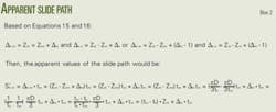
As we proceed from Equations 15 and 16, we follow the analysis shown in Box 2 and reach Equation 22.
A comparison of Equation 22 with Equations 21 and 20 makes their complete identity obvious, the only difference being that the actual slide path for the heel row of the cone along the “alien” sector is found as the arithmetic sum of the completing tooth’s slide path while the apparent value of the same path is the algebraic sum of the same components.
It means that if the direction of slide for the row and the completing tooth in the given sector is the same (both for slow-down and acceleration), then the apparent slide path will correspond to the actual path. Otherwise, the apparent value of the slide path for the heel row of the cone along the “alien” sector will be less than that of the actual path.
Actual slide path
In the general form, the apparent slide path value for the heel row of the cone per revolution of the bit should be put down as S*kn = ± Sk + S*km + S*k-n, while the actual value should be S = Sk + Skm + Skn, where: S*km = ±Smk, S*kn = ±Snk ±Snz, Skm = Smk +Smz, and Skn = Snk + Snz, i.e., S* is shown by Equation 23, and consequently, S*≤S.
Equation 23 shows that the slide path for the heel rows of the cones per revolution of the bit (with different pitch of the heel teeth for all cones) changes five times. Consequently, to calculate the slide path for a single tooth of the given row of the cone, a differentiating approach should be used. There is no sense in determining the value of a single tooth slide dividing the row’s slide path per revolution of the cone by the number of the teeth in the given row. So, the slide path for the heel row of the cone during its movement along its “own” sector, as mentioned above, would fall at the completing tooth. It means that the slide path of this tooth would be equal to the value Sk, as shown in Equation 24.
The other teeth, (Zrk 1), would move along their “own” sector without any skidding.
When the cone moves along the “alien” sectors, the slide paths of individual teeth would be expressed as shown in Equation 25.
Thus, per revolution of the bit (Zrk 2), the teeth of the given cone’s row would skid on the alien sectors of the rack due to the difference in the pitch values of the heel teeth of the cones.
If the apparent gear ratio for the given cone is equal or close to 1.5, then any two of its diametrically opposed heel teeth will constantly perform as the completing teeth, differing in that at each revolution of the bit, one of the teeth would slip on its own and alien sectors of the rack, while the others would slip only on the alien sector. The roles of the cones will change at each revolution of the bit. In this case, similarly to the case considering the cones with equal number of the heel teeth, wear of the teeth rows of the given cone will be uneven.
Yet, if the apparent value of the gear ratio for the given cone differs to a sufficient extent from 1.5, then its completing teeth would change after each revolution of the cone, and that would promote uniform wear of the cone’s teeth.
However, the bit performance data will be predominantly determined rather by the actual value of the teeth slide path than by the extent of wear uniformity.
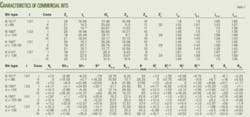
Table 1 represents the estimated data for such values as actual number of the rack teeth Z’a, the apparent and actual gear ratios for the cones iak, ikk, ikm, and ikn, the apparent and actual slide paths of the heel rows Sk, S*km, S*kn, Skm, Skn, S*, and S, the actual slide paths for individual heel teeth Skz, Skmz, Smz, Sknz, and Snz calculated for commercial bits B-151T, B-190T, K-190T, and K-214T, according to the Equations 7, 9, 10, 19, 20, and 22-25. The validity of Equations 9 and 10 may be verified by the equivalent Equations 11-14, 17, 18a, and 18b.
The same table presents, for comparison, values of the teeth row slide paths per revolution of the bit Sx, the specific slide of the row S’x, and the slide paths of a single tooth SZx calculated by the known formulas6 shown in Equations 26-28.
Following the above-mentioned and analyzing the data from Table 1, we come to the conclusion that Equations 26-28 are not quite acceptable for toothed cone bits because they do not give the sought true values.
Actually, as we have found, the slide path of the toothed heel rows of each of the three cones changes five times per revolution of the bit, but taking into account that in their “own” sector (Zrk 1) the teeth are rolling without skidding (i.e., ia = i and S = 0), the gear ratio for the cone per revolution of the bit will change six times. Consequently, the position of the instantaneous axis of the cone rotation will change the same six times.
However, Equations 26-28 include the apparent value of the cone’s gear ratio which does not take into consideration the multiple changes in its rotational speed, i.e., the formulas consider even rotation of the cones per revolution of the bit and a constant position of their instantaneous axes of rotation. Consequently, the presented known correlations, excluding the expression of a single tooth slide path (Equation 28), are acceptable, strictly speaking, only for bits with smooth-tapered cones.
In the next part of this series, to be published Feb. 25, 2008, we’ll discuss one more aspect of the rock bit kinematics.
References
- Potapov, Y.F., and Simonov, V.V., Rock destruction by small diameter three-cone bits. Moscow: Gostoptekhizdat Press, 1961.
- Simonov, V.V., Agoshshvili, T.G., and Brevdo, G.D., “On skidding and designing of insert bit cones.” Moscow: Transactions of the I.M. Gubkin Institute of Petrochemical and Gas Industry, Issue 81, 1968.
- Simonov, V.V., Brevdo, G.D., Vugin, R.B., et al., “On three-cone bit cone rotational speeds.” Moscow: Transactions of the I.M. Gubkin Institute of Petrochemical and Gas Industry, Issue 40, 1963.
- Simonov, V.V., Brevdo, G.D., and Yegorov, A.E., “Comparative test-stand study of the 190-mm bit performance.” Moscow: Transactions of the I.M. Gubkin Institute of Petrochemical and Gas Industry, Issue 96, 1970.
- Pozdnyakov, V.I., Study of impact of the rock bit manufacturing quality on drilling performance. Moscow: Research Institute of Drilling Engineering (VNIIBT), PhD thesis, 1970.
- Paliy, P.A., and Korneyev, K.E., Drill bits Manual. Moscow, Nedra, 1971.


