CLASSIC BIT KINEMATICS—1: Design analysis predicts cone behavior
Drillbit kinematics are defined by the rotation speed and rate of penetration, influenced by the cutting action of the teeth. Each cone of a conventional roller cone bit has several rows of teeth; row placement and tooth pitch may differ for each cone.
Rock drillbit design involves selecting the cone geometry and the shape and layout of the cutting structures. The cone design predetermines the kinematics of the cutting structure and the bottomhole interaction, which subsequently defines the drilling process efficiency and the bit’s susceptibility to wear. Peculiarities of cone bit kinematics determine the cone’s gear ratio value, which sets the magnitude of the cutting structure skidding when destroying the rock.
Currently, the gear ratio of bit cones is estimated either experimentally by keeping records of the bit and cone RPM while drilling in test stand conditions or by calculations that proceed from the cone geometry.1 Calculations of cone geometry are initially derived manually (as shown in this series of articles), but current research focuses on dynamic, iterative solutions using complex equations in bit simulations performed by high-powered computing systems.
Experimentally measuring the cone gear ratio may be a matter of interest because its actual value is uncertain at the bit design stage. However, calculating the gear ratio assuming only the cone geometry may not always provide satisfactory results because it does not take into account the formation of the rack on the well bottom due to the rock exposure to the attacking cone teeth. The rack exerts the determining influence upon the character of the rock bit kinematics, the bit performance, and wear.2
Therefore, it was necessary to develop a technique to calculate the kinematic parameters of the rock cone bits that would proceed from the real process of formation of the bottomhole rack and the consequent specific features of the cone and bottomhole interaction. Moreover, consideration should be taken of the two possible rock bit modifications: those with equal pitch and varied pitch of the heel teeth for all cones.
The material will be presented in four articles. This first part discusses classic bit kinematics when the heel teeth have equal pitch on all cones. The second part, to be published next week, will cover bit kinematics when the heel teeth have variable pitch. The third part will cover the formation of the bottomhole rack, and a study of the performance of rock bits interacting with well bottom during pure rolling of the cones. The concluding part provides field data of more than 1,000 m of hole drilled with a single Varel bit in Tatneft OSC oil fields.
Equal pitch, single cone
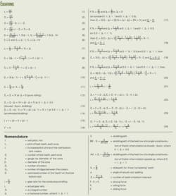
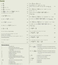
We begin our analysis of bit kinematics with the condition, t1 = t2 = t3 = tc, in which the pitchs of all the heel teeth of all cones are equal, and Z1 = Z2 = Z3 = Zc, in which the number of the heel teeth in each cone is the same. The pitch value tc is always known from the relationship in Equation 1 (accompanying box).
Suppose that the impact of the heel teeth rows of all cones per revolution of the bit results in formation of a definite number of craters Zcr. The number of ridges between the craters, Zrd, will be as large as many times the pitch tc accommodates in the circle circumscribed by the bit with the diameter D·Zcr = Zrd = Zr where Zr is the estimated number of the teeth on the bottomhole rack. Equation 2 calculates Zr. Substituting tc from Equation 1 yields Equation 3.
Estimated in such a manner, the number of the teeth on the bottomhole rack Zr may be an integral or a fractional number, as shown in Equation 4.
Naturally, the actual number of the teeth on the bottomhole rack, Za, will always be equal to some integral value; this explains the difference in values of the gear ratio for the cones at pure rolling and the actual gear ratio. This difference stipulates an occurrence of the rock bit teeth skidding.
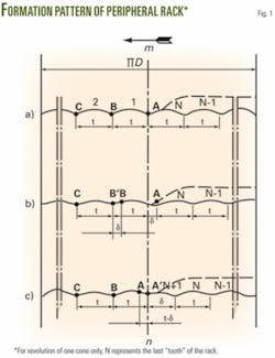
Fig. 1 illustrates the pattern of formation of the peripheral rack on the hole bottom per revolution of the bit, assuming that it has been rolled by one of the cones, for cases when Zr = N (Fig. 1a), Zr = N + Δ at 0 < Δ ≤ 0.5 (Fig. 1b), and Zr = N + Δ at 0.5 << Δ < 1 (Fig. 1c). The line “mn” tentatively marks the boundary where the cone starts its movement in the direction shown by the arrow. The points A, B, and C mark the position of the cone teeth when the bit completes one revolution and starts the next one.
Sections BB’ and AA’ are the paths of the teeth skidding as the result of their sliding down to the bottomhole rack after one revolution of the bit. The direction of the teeth sliding down will determine the movement of the cone: the motion will be either slowed (BB’ the slow-down path, Fig. 1b) or accelerated (AA’ the speed-up path, Fig. 1c).
The phenomenon of the teeth sliding onto the craters was first observed by L.P. Konstantinov and R.M. Eygeles during high-speed filming of the three-cone bit performance.3 Afterwards, this condition was used when analyzing the cone kinematics.4
As shown in Figs 1b and 1c, if a single cone is viewed in the course of one bit revolution, one of the teeth will skid (the tooth is in the ‘B’ position in Fig.1b and in the ‘A’ position in Fig. 1c). The tooth in the ‘C’ position (Fig. 1b) and in the ‘B’ position (Fig. 1c), when cone rotation is continued, will reroll without any slippage due to the pitch equality of the cone teeth and the rack teeth. It is quite evident that at Zr = N (Fig. 1a) the cone will roll over the hole bottom without any skidding.
Thus, the fractional part of the rack pitch δ (Figs. 1b and 1c), equal to δ = Δ·t, will determine the magnitude and the direction of the cone skidding per single revolution of the bit.
Looking at the two skidding paths, BB’ (rotation slowed) and AA’ (rotation accelerated), and a range for rock spalling angle5 (α) of 120-140° (assume α = 120°), we reach Equation 5.
In general, disregarding the sin α/2 value, we calculate S, S1, and S2 in Equation 6.
Triple-cone example
Now, moving from the calculations for a single cone to an actual case in which the bottomhole rack was formed by three cones, our considerations are as follows:
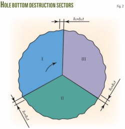
Assume that the bottomhole rack will be formed at a one-third revolution of the bit (Fig. 2). Each cone will roll its own row (sector) of the “teeth.” Equation 7 calculates their estimated number.
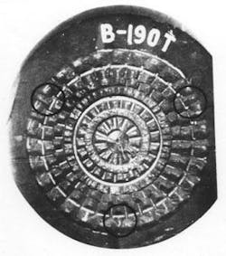
Fig. 3 confirms the validity of this assumption and presents a picture of a steel hole bottom rolled by a commercial B-190T bit with varied pitch of the heel teeth in all cones.
The profile pattern of the peripheral rack formed when the steel hole bottom was drilled evidently confirmed the possible existence of three differing sectors on the bottomhole surface during drilling with a three-cone rock bit. The photograph distinctly shows the borders of these sectors where rearrangement of the rack teeth takes place.
Naturally, it is difficult visually to estimate the difference in magnitude of the teeth pitch of individual rack sectors because of minor variances in the teeth pitch of the heel rows of the cones. (The difference between maximum and minimum pitch for the heel teeth equals 1.95 mm.) However, closer examination reveals the difference, which was confirmed when the value of the rack teeth pitch was measured.
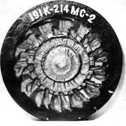
Fig. 4 shows a more convincing picture of the different bottomhole sectors, the metallic hole bottom formed by the 191K-214 MC-2 two-cone bit, with a 3.7-mm difference in the pitch of the heel rows of the cones. Since this is a two-cone bit, there are two sectors on the hole bottom that differ sharply in their profile.
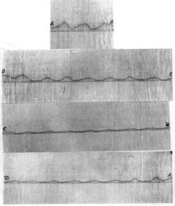
The hypothesis concerning different sectors of rock destruction is also confirmed in Fig. 5, which shows the profile of the peripheral part of the hole bottom formed by the B-190T three-cone bit during drilling of marble.
Based on the experimentally confirmed assumption of the existence of three destruction sectors on the hole bottom during drilling with three-cone bits, we may assert that all our considerations expressed in favor of the bottomhole rack formed by a single cone will be valid for the bit with equal pitch of the heel teeth for all cones.
Here, however, the following condition should be taken into account. If it turns out that N1 = N/3 and Δ1 = Δ/3, i.e., the integral part of Zr value may be divided evenly in three without remainder, then the difference in kinematics of the three-cone combination vs. a single cone will be as follows: each cone, per revolution of the bit, will slide three times for the amount δ1 = δ/3 = Δ1·t, i.e., the skidding path, or slide, S = 3δ1 = Δ·t.
This means that not all heel teeth of the cones will be subject to slide during each revolution of the bit. Only those that complete the motion of the cone in each of the sectors of the well bottom rack will skid.
‘Completing’ teeth
In the general case, there will be three teeth, which we can dub “completing teeth.” Their slide path would be Sz.
After each bit revolution, the completing teeth may be either replaced by other teeth or remain constant. That depends upon the actual value of the gear ratio of the cones, ia.
In particular, if ia = 1.5 or is close to that value, i.e., if each sector of the well bottom rack accounts for 0.5 of the bit revolution, then two diametrically opposed heel teeth of the cones may constantly remain as the “completing” ones. Accordingly, (Zc·ia)/3 = 0.5·Zc or (Zc·ia)/3 ≈ 0.5·Zc.
As to wear resistance of the completing teeth, such a value for the actual bit ratio is not quite desirable because it may lead to fatigue wear and chipping of the teeth resulting from the constant lateral forces, induced by skidding of the cones.
However, if ia does not equal or come close to 1.5, so that, (Zc·ia)/3 <0.5·Zc or (Zc·ia)/3 >0.5·Zc, then, after each revolution of the bit, the completing teeth will replace one another, resulting in a more even wear of the cone’s cutting structures.
Nevertheless, this does not mean that when designing bits one must design the actual bit ratio to be something other than 1.5. In each individual case, one should consider the path of the teeth sliding, which at ia = 1.5, might happen to be substantially less than it is at other gear ratios of the cones.
Another difference in kinematics of the three-cone bit as compared to the single-cone bit, as we ascertained, lies in the fact that when considering a single cone at Δ >0.5, one observes rotary acceleration and skidding equal to S2 = t(Δ1).
Acceleration, deceleration
Considering three cones precludes acceleration since Δ1 in this case is always less than 0.5. The cone skidding, consequently, would be slowed down, equal in its absolute value to S1 = Δt.
In the general case, when N1 ≠ N/3 and Δ1 ≠ Δ/3, i.e., the integral part of Zr value divides in three with a remainder, then, passing from a single cone to three cones, both slowing (at 0 <Δ1 ≤0.5) and acceleration (at 0.5 <<Δ1 <1) of rotation are possible. Moreover, at such transition the phenomenon of acceleration or deceleration may either remain or reverse. The slowing (or acceleration) may even increase, moving more slowly. We can confirm it by the following considerations:
As N1 ≠ N/3, dividing N by three gives a remainder of 1 or 2. Consequently,
N1 ≠ (N1)/3 or N1 = (N2)/3 or, accordingly, Δ1 = (1 + Δ)/3 or Δ1 = (2 + Δ)/3.
If 0 <Δ ≤0.5 (slow-down), then at Δ1 = (1+ Δ)/3 we have 0 <Δ1 ≤0.5, i.e., slow-down occurs, while at Δ1 = (2+Δ)/3 we have 0.5<Δ1<<1, i.e., acceleration or slow-down may occur.
If 0.5<<Δ<1 (acceleration), then at Δ1 = (1+Δ)/3 we have 0.5<Δ1<<1, i.e., slow-down occurs, and at Δ1 = (2+Δ)/3 we’ll have 0.5<<Δ1<1, i.e., acceleration occurs.
At that, the slide path for the heel rows of each of the three cones per revolution of the bit at slow-down of rotation will be equal to S’1 as shown in Equations 8 or 9.
During acceleration, the path will be S’2, as shown in Equation 10. Therefore, S’1 ≥ S’1 and S’2 ≥ S2, where S’1 and S’2 are accordingly the paths of the decelerated and accelerated skidding of the heel rows of each of the three cones, per revolution of the bit.
Keeping in mind that the slide paths of the cone rows account for the three completing teeth, one solves Equation 11 to find the slide path of one of such teeth.
Thus, at Z1 = Z2 = Z3, both deceleration and acceleration of the cone rotation are possible, as conditioned by the value of Zr and the phenomenon of the cone teeth skidding down into the craters of the well bottom rack.
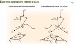
Fig. 6 illustrates the pattern of the teeth skidding into the craters of the rack at the decelerated (Fig. 6a) and accelerated (Fig. 6b) rotation of the cones.
Driving force
As shown in Fig. 6a, the process of slowing the cone rolling over the well bottom rack associated with the skidding of the teeth in the direction of rolling along the line BB’ is conditioned by summing up of the rolling (Frl) and sliding (Fs) forces, F1 = Frl + Fs. The driving force F1 does not impede but, on the contrary, promotes skidding of the teeth down into the crater. This process may be observed in hard and soft formations.
Meanwhile, accelerated cone rotation is associated with the teeth skidding in a direction opposite the rolling along the line AA’ (Fig. 6b). In this case, the driving force F2 = Frl + Fs impedes the teeth skidding and tends to destroy the ridge between the craters.
Varying rock strength
At high rock strength, if there is low torque at the cone, and consequently, low rolling force, the sum of forces F2 = Frl + Fs will not be sufficient to destroy the ridge. The teeth will have to slip along the line AA’, as shown in Fig. 6, and the cone will accelerate. A similar result occurs when drilling at low axial loads.
However, low rock strength promotes an increase in cone torque and rolling force at the expense of greater depth of the tooth penetration into the rock. The ridge between the craters, under the impact of the force F2 = Frl + Fs will be destroyed and the tooth will assume its movement along the line AA’’ (Fig. 6b). This movement will be provoked by the sum of forces F1 = Frl + Fs’ and will result, instead of acceleration, in slowing down the cone rotation.
In other words, if considering geometric relationships of the well bottom rack and the cone permits us to draw this conclusion concerning the slowing of the cone rotation, it should be valid for rock of any strength. At the same time, if the geometric forecast points to accelerating cone rotation, it will be valid for rock of high strength as well as in cases when drilling is performed at low axial loads. In low-strength rock, the process of the cone rotation slowing down is most probable.
Calculating Za
Thus, returning to Fig. 1 and taking into account that the actual number of the teeth of the rack Za, as distinct from the estimated number, is an integral value, we may calculate three values for the number of teeth on a single cone. Equation 12 calculates the number for the pure rolling case; Equation 13 is used for slowed skidding and Equation 14 is used for accelerated skidding.
These three equations indicate that for a single cone, two values of the actual number of the rack teeth are possible. One value corresponds to the integral part of the estimated number of the rack teeth (at 0≤ Δ ≤0.5), while the other is greater by one (at 0.5<< Δ <1).
It is interesting to note that when there is no skidding (when Δ = 0) and at slowed skidding (when 0< Δ ≤0.5), the actual number of rack teeth is the same (N). The difference lies in the increase of the pitch of one of the craters for the value δ = Δ·t, at slowed rotation of the cone (Fig. 1b), shown in Equation 15.
At the accelerated skidding, Za = N + 1, i.e., when an additional crater is created (Fig. 1c), the pitch of the additional crater is shown by Equation 16.
Three cones
Passing from the single cone to the three-cone combination and taking into account Equation 7, we calculate the actual number of teeth, Za, using Equations 17-20.
Considering Equations 17-20, we see that, during drilling with three-cone bits at Z1 = Z2 = Z3, formation of the well bottom rack occurs with four different values for the actual number of teeth: N, N1, N2, and N+1 (N, as mentioned before, is an integral part of the estimated number of the rack teeth):
- At Za = N, there may be pure rolling or a slowing of the cone rotation.
- At Za = N1 or at Za = N2 there may be a slowing of the cone rotation.
- At Za = N+1 there will be acceleration of the cone rotation.
Factors, assertions
Thus, the geometry of the well bottom rack and the character of the multicone bit’s cutter movement (in particular, the three-cone bit with equal heel teeth pitch), are determined by three factors:
- The relationship of the bit diameter and the gauge tip diameter of the cones, i.e., by the value of the cone gear ratio i at their pure rolling.
- The number of the heel teeth on each of the cones Zc.
- Physical and mechanical rock properties.
Consequently, we may assert that:
If N1 = N/3, and Δ = 0, i.e., when the estimated number of the well bottom rack teeth is divisible by three without a remainder, then Za = N, Zr = N, and Za = Zr. Since Za = ia·Zc and Zr = ia·Zc where ia is the actual gear ratio of the cones, then ia·Zc = i·Zc and ia = i. Consequently, the actual gear ratio of the cones in this case will correspond to pure rolling and there will be no skidding of the gauging part of the teeth as conditioned by the cone geometry.This assertion is evidently reasonable both for single and multicone bits of the reviewed designs as all considerations concerning the effects of the cones’ number and their geometric perfection on the cone kinematics and the position of the instantaneous axis of rotation1 are valid only for smooth-tapered cones and are unfit for toothed cones as kinematics of the latter are mostly determined by the interaction of the heel rows with the well bottom rack, by analogy to toothed gearings.
The difference between the single- and multicone bit designs in the given case lies in the fact that considering the perfect cone, pure rolling would be observed at any point of the cone generatrix (generated by a geometric element; Fig. 7a), while in the case of an imperfect cone, any generatrix point, excluding the peripheral one, would skid with acceleration (Fig. 7b).
Back to considering problems of bit kinematics, in particular, the absence of skidding of the gauge teeth at Za = N, we proceed from the cone geometry and do not consider the phenomenon of the cone skidding due to the cutting structure and the rock interaction. According to our data, the amount of such skidding is relatively small; its specific value is less than 1% and therefore it may be neglected.6
• If N1 = N/3, Δ1 = Δ/3, and 0<Δ<1, i.e., when the integral part of the estimated number of the rack teeth divides by three without a remainder, then, according to Equation 17, Za = N and Zr = N+Δ. This means that ZaTo calculate the difference in values of the given cone gear ratios, keep in mind that Za = ZrΔ, we put down: ia·Zc = i·ZcΔ, which leads to Equation 21.
As we see, the actual gear ratio for the cones at Z1 = Z2 = Z3, N1 = N/3 and 0<Δ<1 is less than in the case of pure rolling for the value Δ/Zc.• If N1 = (N1)/3, Δ = (1+Δ)/3, and 0<Δ<1, i.e., when the integral part of Zr is divisible by three, with a remainder of 1, then, according to Equation 18, Za = N1 and Zr = N+Δ. This means that Za Equation 22 shows the difference in ia and i values. Comparing Equations 21-22, we see that ia in the given case is substantially less than the previous (for the value of 1/Zc), and the slowed skidding of the cones, consequently, will be more pronounced. • If N1 = (N2)/3, Δ1 = (2+Δ)/3, and 0.5 <<Δ<1, i.e., when the integral part of Zr value divides by three with a remainder equal to 2, and 0.5<<Δ<1, then, according to Equation 20, Za = N+1, and Zr = N+Δ. This means that Za >Zr and ia>i, and the calculation of ia is shown by Equation 24. Thus, we have established that, if the pitch for the heel teeth of all bit cones is equal, i.e., Z1 = Z2 = Z3 = Zc, then, depending upon the values of i and Zc, the actual gear ratio for the cones, ia, may have five values: It is evident that Zc → ∞, ia = i. When you analyze these formulas that predict the actual gear ratios for cones with equal tooth pitch for all heel rows, pay attention to the following: Taking into consideration that the gear ratio for the cones of the standard three-cone bits in the case of pure rolling is somewhere in the range i = 1.5÷1.6, i.e., i = (3/2) + ξ, and being aware that i·Zc = N+Δ, we can write: (3/2 + ξ)·Zc = N+Δ or (3/2)·Zc + ξ·Zc = N+Δ. Thus, if Zc is an even number, then (3/2)·Zc = N, while ξ·Zc = Δ. Consequently, if Zc is an even number, then N = 3·(Zc/2) = Za, while if Zc is an uneven number, then N’ = 3·(Z’c/2) = Zc·Z’c is the nearest to Zc even number, i.e., Z’c= Zc ± 1. This means that with an equal number of heel teeth on all cones, Zc, the actual number of well bottom teeth Zc should be divisible by three. Besides, if Zc is an even number, then ia = Za/Zc = ((3/2)Zc)/Zc = 3/2 = 1.5. This agrees with test-stand studies of rock-bit kinematics with heel rows made in the form of circumferential teeth.7 These bits have an equal number of heel teeth on all cones, Zc = 10. In all drilling tests, the rack formed in the angular zone of the well bottom with 15 teeth (Za = 15), and the same number of textural marks (grooves) was formed on the well wall. Accordingly, the actual gear ratio for the cones was ia = Za/Zc = 15/10 = 1.5, confirmed by the recorder. It’s notable to mention that the circumferential teeth form a more conservative geometry in the well bottom rack when compared with the geometry formed by longitudinal teeth. This means that if cones with longitudinal teeth can form the well bottom rack with varying number of craters, depending upon rock properties and differing operational and technological factors, then the cones with equal-pitch circumferential heel teeth will form the well bottom rack with a constant number of craters in all drilling cases. During drilling with 20B-151T drillbits (manufactured following the standard B-151T bit design, with an equal number of peripheral longitudinal teeth on all cones, Zc = 20), testers recorded ia = 1.5, indicating that the well bottom rack had 30 peripheral craters.Actual gear ratio
Test results
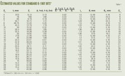
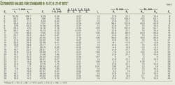
Tables 1 and 2 present estimated values Zr, Za, ia, S, and Sz for the B-151T, B-190T, and K-214T bits. All three bit cones have equal numbers of heel teeth, Zc, across a wide range from Zc = 4 (a bit with such number of the teeth was some time ago recommended by Vladislavlev4) to Zc = 30.
As seen from the tables, the actual gear ratio for cones with equal pitch of heel row teeth may correspond to pure rolling, not only at large and unpractical numbers of heel teeth, Zc, but also at some lower, practical Zc values.
For instance, with the B-151T and K-214T bits, which have the same gear ratio i = 1.573, ia = i at Zc = 21, while for the B-190T bit, ia = i is behind the range of practically justified Zc values (ia = i, e.g., at Zc = 49).
This means that in order to minimize rock bit cutting structure skidding, there should be 21 heel teeth on all cones of the 151-mm and 214-mm bits. But on similar cones of 190-mm bits, there should be an even number of heel teeth.
Commonalities
Thus, when there is an equal number of heel teeth on all cones, the following commonalities are seen in three-cone bit kinematics:
- The actual number of the rack teeth tends to be divisible by three because the well bottom rack in the given case consists of three equal sectors. A certain number of the teeth has been rolled in each of the sectors.
- If the cones have an even number of heel teeth, their actual gear ratio tends to be 1.5.
- For some bit sizes (e.g., 151-mm and 214-mm), the actual gear ratio for the cones may correspond to pure rolling at definite, practically applicable numbers of cone heel teeth.
- The cones make a threefold skidding of their completing teeth per revolution of the bit. The path of their skidding is Sz = S/3, where S is the path of the given heel row skidding per revolution of the bit.
- At ia = 1.5, the skidding path Sz = S/3 constantly falls at some two diametrically opposite teeth of the given row of each cone, while at ia values different from 1.5, the skidding path Sz = S/3 during the bit rotation is equally redistributed between all teeth of the given row.
Kinematics of bits of the double- and multiple-cone design can be analyzed in the same way. It should be taken into account that in each individual case, the number of sectors of destruction on the well bottom will be equal to the number of the bit cones.
References
- Paliy, P.A., and Korneyev, K.E., Drill bits Manual. Moscow, Nedra, 1971.
- Potapov, Y.F., and Simonov, V.V., Rock destruction by small diameter three-cone bits. Moscow: Gostoptekhizdat Press, 1961.
- Konstantinov, L.P., and Eygeles, R.M., “Experience in three-cone bit performance study by means of high-speed filming,” Neftyanoye Khozyaystvo, No. 3, 1955.
- Vladislavlev, V.S., Rock destruction in the process of well drilling. Moscow: Gostoptekhizdat Press, 1958.
- Shreiner, L.A., et al., Mechanical and abrasive rock properties. Moscow: Gostoptekhizdat Press, 1958.
- Palashchenko, Y.A., Test-stand study of kinematics and dynamics of nonimpact-action rock bitsWell drilling and oil production problems. Baku: Azneftekhim, 1973.
- Simonov, V.V., et al., Development of nonimpact-action bit design. Report on theme No. 244-67. Moscow: I.M.Gubkin Institute of Petrochemical and Gas Industry, 1970.
The author
Yuri A. Palashchenko ([email protected]) is a technical sales representative for Varel International Inc., Russia. Before joining Varel in 2001, he served as a technical manager at Security DBS Drill Bits, a Halliburton subsidiary (1995-2001) and as technical coordinator at Smith EA Energy (1993-95). Prior to that, Palaschenko spent 27 years at the Moscow Gubkin Petroleum Institute, as chief of the research drilling laboratory (1976-93) and as a postgraduate and researcher (1966-76). He also worked as a designer and researcher at Kuibyshev Drill Bit Plant (1961-66) and as a drilling engineer at Kuibyshevneft (1959-61). Palashchenko earned a BS (1959) in drilling engineering from Kuibyshev Industrial Institute; a BS (1965) in telemechanics engineering from Kuibyshev Polytechnic Institute; and a PhD (1974) in drilling of wells from Moscow Gubkin Petroleum Institute. He is a member of SPE.
