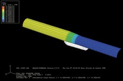
UFRJ, Petrobras study strength behavior of expandable tubulars
Researchers at COPPE/Federal University of Rio de Janeiro and Petrobras present a method for determining the necessary diameter-to-thickness ratio of tubulars corresponding to required minimum collapse pressures. The article describes the theoretical and experimental studies used to evaluate the behavior of solid expandable tubes.
Solid expandable tube technology has many advantages when compared to conventional technology for wells. The expansion of tubes in situ allows development of reserves in many different scenarios found in the oil industry; the technology is compatible with directional and horizontal wells, and facilitates side-track operations.
Although the expansion of tubes is attractive, a better understanding of its influence on the tube mechanical strength is necessary. This article explains the methodology of experimental tests and numerical analyses used to determine the effect of parameters such as diameter-to-thickness ratio and expansion rate on the collapse resistance of expandable tubes. We developed non-linear numerical models using finite- element analysis and, after calibration, used them to analyze further the mechanical behavior of solid expandable tubes and the influence of expansion on tube resistance to collapse.
Background
A 2-3%/year increase in the already high demand for energy, oil in particular, is expected for the next few decades (Energy Information ADministration, 2006). As a result, oil companies are intensifying efforts to meet global demand. These efforts must be made in E&P, especially towards the discovery and development of new reservoirs, by improving the performance, developing feasible new technologies, and reducing costs. Once drilling and completion represent a major percentage of the field development cost, companies will concentrate their efforts on those segments.
Some of the current challenges in drilling and completion segments are: high-pressure/high-temperature drilling; drilling through salt layers; deep wells; ultradeepwater horizon; extended-reach wells; complicated trajectory wells; and rig availability.
With more than 1,000 installations in place, solid expandable tubular has proven to be an economically and viable alternative to conventional drilling technology. Originally developed to extend well depth while maintaining larger borehole diameter (monodiameter or slim well system), expandable tubes can also be used as a contingency drilling liner in any well. Drilling liners are used to maintain hole size when a geographical anomaly or problem is encountered.
Another application is the openhole cladding system. It consists of an expandable string with elastomers that is run and expanded against the formation to isolate specified areas. The cladding differs from the liner system because it is not tied back to the base casing.
Expandable tubular technology can be used in cased holes as well. The expandable cased hole liner system enables operators to repair existing damage or worn casing in deep drilling or other contingencies.
Expansion process
The expansion of solid tubes is a cold work process inside the well that expands the diameter of a liner by passing a mandrel through it. Expansion may result in a decreased thickness and a variation in length of the expanded body. It also results in stress-induced material anisotropy.
For a downhole expansion process, the capabilities required include:
- Expand the tubular to the desired diameter without fracturing, bursting, or damaging the tubular
- Maintain structural strength of the expanded tubular to provide sufficient resistance to burst and collapse loads in service
- Achieve a constant diameter and wall thickness of the expanded tubular over the whole length of the expanded section
- Maintain integrity of expanded tubular connections
- Expand long sections at high rates.
The expansion can be performed both in open and cased holes. In open holes, the tube is expanded against the formation. In cased holes, the tube is expanded against casing previously installed in the well. Different service companies use different expansion methods.
Experimental tests
We performed experimental tests on specimens taken from expandable tubes dedicated to oil well applications, provided to the lab by Petroleo Brasileiro SA (Petrobras).
To have good representation of the studied phenomenon (radial expansion of pipes), we developed an expansion apparatus in the Subsea Technology Laboratory (LTS) of the Federal University of Rio de Janeiro to carry out the experimental tests.
Material properties
Because the material parameters of the tubular samples were not provided by the manufacturer, we determined them from uniaxial tension tests, based on nine specimens removed from the tubes in the longitudinal direction (three samples per tube).
We determined the elastic characteristics of the material (yield strength and Young’s modulus) and obtained a stress-strain curve in the elastic-plastic regime.
One of the three specimens of each tube was instrumented with two uniaxial strain gages, applied in the longitudinal direction, a uniaxial strain gauge in the transversal direction and a clip gauge. The other two specimens received only the clip gauge.
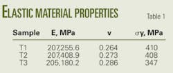
We conducted the tests according to ASTM’s E8M standard. Table 1 shows the material elastic properties.
Expansion apparatus
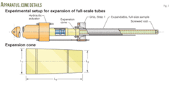
As previously mentioned, an experimental setup was designed and built at the Subsea Technology Laboratory to reproduce the expansion of full-scale tubulars with diameters up to 152.4 mm. Its function is expanding the tube under tension. The main parts are hydraulic actuator, grips, and screw-driven expander cone.
The cylinder imposes displacement to the expander cone through a long screw. The cone, in turn, expands the tube in the radial direction. One edge of the tube (where the expansion process begins) is fixed by grips, while the other end remains free.
The expansion is carried out in three steps. Initially, the cone is forced inside the tube between one edge and the first-stage grip with the hydraulic cylinder. Then we remove the first-stage grip and force the cone further along the length of the tube until the maximum displacement of the cylinder rod is achieved (second stage). Because the maximum extension of the cylinder rod is insufficient to perform the whole expansion, another expansion stage is necessary.
Then we retract the rod and move the screw through the cone to follow the rod tip. Finally, we actuate the hydraulic cylinder again against the screw to finish the expansion process (third stage).
Fig. 1 outlines the apparatus and details of the expander cone. The cone has a cylindrical hole along its entire length with screw profile. The dimensions of the cone, L1, L2, and L3, are respectively 154, 133, and 309 mm.
Solid tube expansion
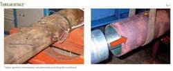
We expanded three solid expandable specimens, each 2 m long, to 1.10 times their original diameter, and used strain gauges to calculate hoop and axial strains. Using the apparatus presented previously allowed us to evaluate the deformation behavior during the expansion and to calibrate the numerical model. Fig. 2 shows the expansion process of a solid tube with the grip in the second and third stages.
The outer diameters and the thickness of each specimen were determined before and after the expansion on 10 different sections. We measured each section using 10 equidistant points (36° between each point) and recorded a total of 10 thickness dimensions and 5 diameters. Fig. 3 shows details of the measurement points.
null
Table 2 contains geometric data, collected before and after the expansion, of the three expanded specimens of solid tubes (T1SFE-01, T2SFE-02, T3SFE-03) and of the three nonexpanded tubes used in this work. It also contains the average ovalization for each tube calculated with the following equation, where Δo = ovalization, and Dmax and Dmin represent the maximum and minimum diameter in a given section:
- Δ o = (D max – D min)/( D max + D min)
Table 2 shows an ovalization increase when a decrease was expected. This may be explained by the gap between the outer cone surface and the inner solid tube surface during expansion. Thus, the cone does not exactly imprint its circular geometry onto the tube. The tube, in turn, maintains its ovalized section, which in some cases is aggravated with the expansion. The eventual existence of this gap is mentioned by Pervez et al. (2007). The tube eccentricity is another factor that may increase the ovalization.
After the first expansion stage, we outfitted specimen T3SFE-03 with six electric strain gages. We placed the instrumentation in Section 3, 1,025 mm from the edge where expansion begins. We installed the strain gauges in pairs, in hoop and longitudinal directions, in three different points along the section chosen: 0°, 90°, and 180°. Fig. 3 shows this distribution. We outfitted the hydraulic cylinder with a pressure transducer.
The pressure applied to the cylinder, limited to 3,000 psi, controls the expansion test. Thus, the expansion rate was low, and the radial expansion followed a quasistatic process with a deformational gradient only in the region of pipe under expansion. As soon as the tube length shortens while the diameter is expanding, the transverse gauges mark an increase in strain, and the longitudinal ones show decreased strain. We observed limited elastic strain recovery.
Collapse tests
We performed the collapse tests in a pressure vessel at the Subsea Technology Laboratory, COPPE, the Alberto luis Coimbra Institute for graduate engineering project coordination, at the Federal University of Rio de Janeiro (UFRJ).
The vessel was filled with water until all the air was evacuated from its interior. The pressurization occurred at lower than 100 psi/min, with a flow-control valve. Other equipment included:
- Hyperbaric vessel with capacity of 7,500 psi.
- 30,000-psi hydraulic pneumatic drive pump (Haskel).
- 15,000-psi pressure transducer.
- Signal conditioner module SCXI-1001 (National Instruments AQD002M2).
- Microcomputer with A/D board for data acquisition.
The expanded tubes had their initial ends cut off to prevent undue influence of the boundary conditions in the expansion process on the collapse pressure. Thus, the specimens remained with a length of 1,500 mm instead of the original 2,000 mm.
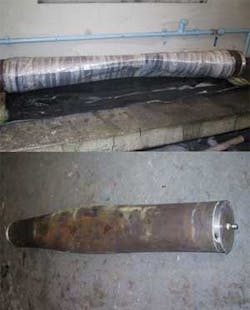
Seeking the collapse pressure determination, we tested three expanded solid tubes in the pressure vessel. For purposes of comparison, we also exposed three nonexpanded solid tubes to external pressurization. The collapse occurred in the central portion of each solid tube specimen (Fig. 4).
Fig. 5 provides a representation of the results of the collapse tests performed on the six solid tubes. Among the expanded tubes, specimen T3SFE-03 showed the greatest resistance against collapse. However, the geometric properties of the tube (ovalization, OD, WT, D/t ratio) do not explain this behavior.
As expected, the nonexpanded solid tubes (specimens T3SFI-01, T3SFI-02, and T3SFI-03) exhibited collapse pressures significantly greater than those exhibited by the expanded tubes. On average, the collapse pressure of the expanded tubes was nearly 50% lower than the collapse pressure of nonexpanded tubes.
Finite-element modeling
We developed nonlinear numerical models using the finite-element method that employs Abaqus software (Version 6.5-1), which can simulate the cold-expansion process and the behavior of solid tubes under external pressure. The modeling took into account material kinematic hardening, contact between tubulars and the conical expander, and geometrical nonlinearities.
We simulated the expansion process and the external pressure loading until collapse, using implicit integration of the equilibrium equations in two steps. The models were capable of successfully reproducing the physical experiments. After using experimental results to calibrate, we used the models to analyze further the mechanical behavior of solid expandable pipes and the influence of the expansion process in their structural strength against collapse.
Geometry
We developed 3D finite-element models of a solid tube and a conical mandrel using Abaqus (Fig. 6). Since there is no axial symmetry that allows reduction of the model, the tube geometry was build with the same length of the tube, after it had been prepared for collapse test (1,500 mm). The model had one angle symmetry in Direction 2 and one in Direction 3. Therefore, only one fourth of the tube was modeled, reducing the number of equations to be calculated and, consequently, the computational time.
We built the geometry of each tube as a deformed body, based on the actual geometric properties of each tube. The values used were the average diameter and thickness and the maximum ovalization found along the length of each specimen. We created the mesh in a Fortran routine to allow the model section to have an elliptical shape. It provides the desired ovalization, which has a maximum value in the middle of the tube and decreases toward each end.
We modeled the cone as an analytical rigid body, with a reference point (RP) to control its displacement and permit the expansion. Its corners, where contact may take place, were smoothed to avoid any possibility of inducing stress concentration.
Material properties
The finite-element model requires the material properties of the solid tube in order for us to study its structural response under expansion and external pressure.
Since the tubular undergoes large plastic deformation, we used an elastic-plastic material behavior. We followed a kinematic hardening plasticity model in addition to the isotropic model in order to simulate the Bauschinger effect (reduced yield stress under reverse loading after plastic deformation has occurred in the initial loading). The material properties input to the program depend on the tube being analyzed and are based on the properties determined from the uniaxial traction tests.
Mesh
We used 3D quadratic solid elements (C3D27) and carried out a refinement study to determine the ideal mesh. A typical mesh had 80 elements in axial direction, 2 elements in thickness, and 10 elements in the angular direction. The angular direction was divided in the following configuration, with one element in every section: 10°, 10°, 15°, 15°, 10°, 10°, 7.5°, 7.5°, 2.5°, and 2.5°. In this way, areas that are expected to suffer larger deformations and stress were more refined. Fig. 6 shows details of the mesh of the tube.
Interaction, load, boundary conditions
We modeled the contact between the mandrel and the internal surface of the tube in accordance with the Coulomb’s friction law, but because the experiment was conducted with grease between the surfaces, we set the friction coefficient equal to zero. In future simulations, this parameter can be easily changed to add the friction effect.
During the first step, as in the expansion test, no load was applied. In the second step, to simulate the collapse test, we applied pressure on the external surface of the tube and an equivalent pressure, in axial direction, on the lateral area of the tube. The latter pressure was used to reproduce the effect of hydrostatic load that occurs inside the hyperbaric vessel (Fig. 7).
In order to reproduce the experimental tests, we used specific boundary conditions. During the first step, the edge of the tube where the expansion begins was constrained in direction one (axially), simulating the second and third-stage grip assembly. In addition, we applied an axial displacement to the cone reference point to move it forward while it was being constrained from rotating. For the collapse step, one end was constrained in all directions, while the other edge remained free in the axial direction. We varied the boundary conditions, in displacement and velocity. Fig. 7 contains loads and boundary conditions for both steps.
Numerical results
During the analysis of the expansion step, we monitored the strains of the tube and compared them to the results obtained during the experimental test. Fig. 8 refers to a node in the middle portion of the tube situated in coordinates (6.56250e + 002, 7.57703e + 001, 0.00000e + 000), belonging to numerical model T2SFE-02. Fig. 9 shows a plot of equivalent plastic strain at integration points along the tube.
null
The model reproduces only the quasistatic process of expansion (deformation occurs just in the region that is being expanded); it shows a small plastic strain recovery that was not read by the acquisition system used in the experiment but can be seen on the graph in Fig. 9. The final displacement in Direction 2 for Node 50171 was 7.27 mm, which results in a deformation of 10.08% (at this node). The average deformation on the experiment was 9.81%. We observed similar behavior for all models developed.
To determine the collapse pressure for the expanded tube, or the nonexpanded ones, we applied pressure on the external surface. We chose to use the Modified Rik’s algorithm for load-deflection analysis because the load is proportional and the solution exhibits instability.
Fig. 10 presents the positive collapse configuration for numerical model T2SFE-02, the displacement in Directions 3 and 2 are plotted along the tube length. An elevation in Direction 3 is seen while a sink occurs in Direction 2. As observed on the experimental tests, the tube assumes an infinite symbol configuration.
Fig. 11 shows how the Bauschinger effect and the hydrostatic loading are important on the numerical analyses for determination of the collapse pressure sought in this work.
We developed two extra models for specimen T2SFE-02: one not taking in consideration the Bauschinger effect (T2SFE-02NBE) and the other disregarding the hydrostatic effect during the collapse test (T2SFE-02NHL). Although the difference between the original model and the model without axial loading is small for this case, it does vary from model to model depending on the geometry and process being analyzed.
When the Baushinger effect is disregarded, the difference between the determined collapse pressures is much bigger. Model T2SFE-02NBE showed a collapse pressure 65% greater than the original one given by model T2SFE-02. Thus, the inclusion of both effects is essential for the model reliability.
Experimental-numerical correlation
Table 3 contains results from experimental tests and numerical analyses; it also shows the difference in percentage between both collapse pressures. To achieve this correlation, we adjusted the numerical model to reproduce the experiments.
We found good correlation between experimental tests and numerical analyses, proving the reliability of the numerical model. Once validated, the model can be used to analyze further the expanded tube behavior and to realize a parametric study.
Parametric study
Fig. 12 shows the relation between the collapse pressures (Pc), for expansion ratios ranging from 5% to 20%, and the collapse pressure (Pco) of the nonexpanded tubulars.
For each expansion ratio, we carried out different analyses, varying the tubular diameter-to-thickness ratio (D/t) between 14 and 26. Table 4 shows the collapse pressure (Pco) of the nonexpanded tubular for each D/t. The maximum ovalization in the midsection of the model was 0.5%, and the material properties were the same as used for model T2SFE-02.
We observed a considerable reduction in collapse pressure with increasing expansion ratio. This reduction is related primarily to changes in geometry (D/t ratio) and, as mentioned on the preceding page under the Numerical results subhead, to the stress induced anisotropy caused by strain-hardening (Bauschinger effect). Interestingly, expansion has an overall very similar detrimental effect in tubulars with different D/t ratios. On average, an expansion of 5% results in a 29% decrease in collapse pressure (Pc/Pco = 71%). For expansion ratios of 10%, 15%, and 20%, the average values of Pc/Pco are 58%, 52%, and 48%, respectively.
This parametric study allows determination of the D/t ratio needed to obtain a specific collapse pressure for a tubular after it has been expanded to different magnitudes. In order to find the necessary diameter-to-thickness ratio, the original collapse pressure (Pco) of the tube must be calculated.
For example, if in a given scenario the minimum collapse pressure required is 15 MPa, one can choose different combinations of D/t and expansion rates as follows: D/t = 26 (Pco = 2.54 MPa) with an expansion of 5% (Pc/Pco = 71%); D/t = 23 (Pco = 27.57 MPa) with an expansion of 10% (Pc/Pco = 58%); or D/t = 20(Pco = 35.7 MPa) with an expansion of 15% (Pc/Pco = 52%). If the D/t ratio is fixed, one can choose a suitable expansion rate for a specific design pressure.
Learnings, future
After carrying out uniaxial tension tests, for material characterization, then expansion and collapse tests on three solid tubes in a hyperbaric vessel, we found:
- Insignificant elastic strain recovery after the expansion.
- Tubular expansion results in geometry and material changes.
- Initial ovalization did not reduce with the expansion for all specimens tested.
- Collapse pressure of pipes after 10% expansion was, on average, 50% of the original pipe collapse pressure for the geometries and material tested.
Different pipe and cone geometries, expansion rates, and boundary conditions must be tested in future studies to further analyze the behavior of solid expanded tubes.
Bibliography
Campo, Don, Williams, Charlie, Cook, Lance, Brisco, David, Dean, Bill, and Ring, Lev, “Monodiameter Drilling Liner—From Concept to Reality,” Paper 79790, SPE/IADC Drilling Conference, Amsterdam, Feb. 19-21, 2003.
Fonseca, Carlos Eduardo, “Análise do Comportamento Estrutural Sob Pressão Externa de Tubos Expansíveis para Poços de Petróleo,” MSc thesis in Engenharia Oceânica, Universidade Federal do Rio de Janeiro, COPPE/UFRJ, 2007.
ASTM E8M, “Standard Test Methods for Tension Testing of Metallic Materials [Metric],” ASTM International, 2001.
Pervez, T., Qamar, S.Z., Seibi, A.C., and Al-Jahwari, F.K., “Use of SET in cased and open holes: Comparison between aluminum and steel,” Journal of Materials & Design, 2007, article in press doi:10.1016/j.matdes.2007.01.009.
ABAQUS, User’s Manual and Theory Manual, Release 6.6 EF, Hibbitt, Karlsson, Sorensen Inc., 2006.
Grant, Tom, and Bullock, Michael D., “The evolution of Solid Expandable Tubular Technology: Lessons Learned Over Five Years,” Paper 17442, Offshore Technology Conference, Houston, May 2-5, 2005.
Seibi, A.C., Pervez, T., Al-Hiddabi, S., and Karrech, A., “Finite Element Modeling of a Solid Tubular Expansion—A Typical Well Engineering Application,” Paper 84943, SPE International Symposium on Formation Damage Control, Lafayette, La., Feb. 20-21, 2002.
Stewart, R.B., Marketz, Franz, Lohbeck, W.C.M., Fisher, F.D., Daves, W., Rammerstorfer, Franz G., and Bohm, H.J., “Expandable Wellbore Tubulars,” Paper 60766, SPE Technical Symposium: Quest for Solutions in a Changing Industry, Dhahran, Saudi Arabia, October 1999.
Lunliner, J., Plasticity theory, 1st ed. 1990, New York: Macmillan Publishing Co..
The authors
Ana Carolina Caldas Aguiar ([email protected]) is a graduate student at COPPE-Federal University of Rio de Janeiro. Aguiar holds a BS (2008) in petroleum engineering from Federal University of Rio de Janeiro. She is a member of the Society of Petroleum Engineers.
Theodoro Antoun Netto ([email protected]) is an associate professor in the ocean engineering department at COPPE-Federal University of Rio de Janeiro. He has also served as a technical consultant for Petrobras since 2004. Netto holds a BS in naval architecture from UFRJ, an MSc (1991) in ocean engineering from COPPE-UFRJ, and a PhD (1998) in engineering mechanics from the University of Texas at Austin. He is a member of the American Society of Mechanical Engineers, the American Academy of Mechanics, the Society for Underwater Technology, and the Brazilian Academy of Mechanical Sciences.
Carlos Eduardo da Fonseca ([email protected]) is a petroleum engineer at Petrobrás R&D center Leopoldo A. Miguez de Mello, Rio de Janeiro. He holds an MSc (2007) in ocean engineering from Rio de Janeiro Federal University and a BS (1998) in civil engineering from Sao Paulo State University. Fonseca is an SPE member and serves on the SPE editorial review committee.

