Crude Export Riser — 1: Hybrid riser application provides deepwater crude export solution

The freestanding hybrid riser concept allows decoupling the schedules of riser and floating production unit design, manufacture, and installation, providing flexibility should delays occur during FPU construction. Uncertainties in FPU construction schedules and the low availability of specialized construction vessels pose a risk of delay if the chosen riser concept requires the FPU to be in place at the time of installation.
Petrobras’s development plan for the Roncador field offshore Brazil included an FSHR as part of its oil export system.
This first of three articles describes the FSHR in detail before examing its design and installed responses. Subsequent articles in the next two issues will detail FSHR installation and monitoring, as well as its integration with the export pipeline.
Background
Petrobras’s oil flow master plan (PDET) for development of Roncador field in the Campos basin off Brazil consists of the P-52 semisubmersible oil-export system, an 18-in. OD oil-export pipeline, and a freestanding hybrid riser (FSHR) connecting the P-52 floating production unit (FPU) to fixed platform PRA-1, also in the Campos basin. P-52 is stationed in water 1,800 m deep; PRA-1 is in about 100 m (Fig. 1).
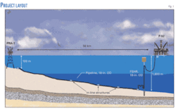
A front-end engineering and design (FEED) project contracted to 2H Offshore Engineering and based on technical specifications and functional requirements provided by Petrobras developed the FSHR. Flow-assurance studies required 50-mm thick thermal insulation for both pipeline and the vertical portion of the riser.
The FEED process considered a mobile offshore drilling unit (MODU) for deploying the FSHR system, to take best advantage of local practices and Petrobras’s capabilities. Bid requirements allowed some changes to the design and installation procedure developed during the FEED phase, in order better to suit the contractor’s capabilities. As a result, a pipelay and construction vessel were considered for installation of both riser and pipeline. Technip won the contract, excluding the flexible jumper, awarded to Wellstream, and the foundation, to Petrobras.
High expected production rates at P-52 required an 18-in. oil export pipeline. Instrumented pigging requirements dictate the export riser have the same diameter. This large-bore specification, combined with the deepwater site, put this application outside the present range of flexible-pipe and steel catenary riser (SCR) solutions, both of which present high top-tension loads for installation and operation. Lateral buckling failure in flexible pipes and fatigue damage in the touchdown zone (TDZ) of SCRs further limitated design to heavier pipes, compromising hang-off loads.
The reduced dynamic response of the FSHR system results in a motion decoupling between the floating production unit (FPU) and the vertical portion of the FSHR system. FSHR’s vessel interface loads are also small when compared with SCRs or flexible pipe, making it an attractive alternative solution for this kind of application. Additional cost savings accrue by having the riser in place before FPU installation.
Design changes
The FSHR FEED awarded to 2H Offshore Engineering considered the following requirements:
- Flexible jumper, replaceable at any time.
- Installation by MODU.
- Welded riser joints.
- SPP thermal insulation = 50 mm.
A drilled and grouted pile installed by MODU was to provide FSHR’s foundation. During FEED development, Petrobras established that, due to installation and maintenance requirements, the connection of the flexible jumper at the FSHR side would occur on top of the buoancy can (BC). A detailed structural design analysis considered passing the riser stem through the BC.
Petrobras free-issued a MODU for FSHR installation as an option in the bid package, assuming FSHR foundation and flexible jumper installation as part of its work scope. Petrobras initially issued different offers for pipeline and FSHR. Bid requirements allowed changes to the FEED to suit contractors’ capabilites, including locating the flexible jumper connection on the FSHR’s side. Bidders only proposed pipelay and construction vessels for installation of the riser and pipeline. The contract awarded to Technip included development of the detailed design, material supply, fabrication, and installation of both pipeline and riser.
FSHR description
FSHR design may have a number of variants. An optimazation study determines actual configuration considering:
- Offset from the foundation to the FPU.
- Net upthrust provided by the BC.
- BC depth.
- Flexible jumper length
- Flexible jumper azimuth (plan view).
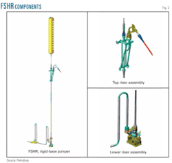
The FSHR consists of a single nearly vertical steel pipe connected to a foundation system near the mud line. A BC holds the riser in the proper vertical orientation and is mechanically connected to the top of the vertical pipe by a chain. The BC lies below sea level, beyond the influence of waves and high currents. A gooseneck assembly sits on top of the top riser assembly (TRA). A flexible jumper links the gooseneck to the FPU, effectively decoupling the vertical part of the FSHR from vessel motions. Fig. 2 shows the FSHR’s general arrangement.
The FSHR runs from the No. 1 hang-off slot on P-52 to the pipeline-end termination (PLET) near the riser base. The lower end of the vertical part interfaces with a stress joint. Below the stress joint lies an offtake spool, connected to the foundation by a hydraulic connector. A rigid base jumper connects the mandrels at the offtake spool with the PLET, providing the link between the FSHR and the pipeline. The foundation pile is drilled and grouted.
The upthrust from the nitrogen filled BC on top of the vertical pipe provides the tension. The vertical pipe must be kept in tension to maintain FSHR stability for all loads. The vertical pipe consists, from top down, of the upper-taper stress joing (UTSJ), interfacing with the TRA, the upper-adapter stress joint (UASJ), standard joints, the lower-adapter stress joint (LASJ), and the lower-taper stress joint (LTSJ), interfacing with the offtake spool.
At the top of the TRA is the gooseneck assembly. This assembly consists primarily of the gooseneck and an ROV actuated hydraulic connector allowing the gooseneck and flexible jumper to be installed separately from the vertical section of the riser. The gooseneck assembly also includes a cross-brace tied to a reinforced spool to provide support against loads applied to the gooseneck from the flexible jumper.
Attached to the gooseneck is the flexible jumper (FJ). The flexible jumper connects the freestanding section of the riser system to the FPU, and includes bend stiffeners to ensure the range of rotations experienced at the end connections do not damage the jumper due to low radius of curvature. The flexible jumper has sufficient compliance to decouple vessel motions substantially and offsets from the vertical portion of the FSHR system, limiting the freestanding riser’s wave-induced dynamic response.
Positioning the gooseneck at the TRA allows for independent installation of vertical riser and flexible jumper. A flexible pipe installation vessel can install the flexible jumper when convenient, minimizing the risk of damage to the flexible jumper during installation. The horizontal offset between the mandrel at the TRA and the BC vertical axis allows installation and retrieval of the flexible jumper. This design also minimizes time needed for flexible jumper retrieval in case of damage while in service to any of its components.
FSHR components
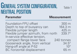
Table 1 presents the main characteristics of FSHR configuration at neutral position. Water depth measures 1,800 m and design life is 25 years. The fatigue safety factor is 10. In the neutral position the FJ is already connected and the system is subject to weight and buoyancy loads only, displacing the TRA toward the FPU.
The vertical part of the FSHR consists of an assembly of both standard and special joints, such as the stress joints at the bottom and top interfaces. Table 2 presents the main characteristics of the line pipe (standard joints) and its operating parameters.
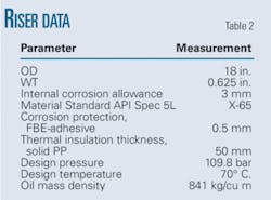
Table 3 shows the flexible jumper’s main characteristics.
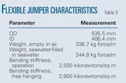
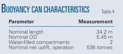
Table 4 outlines the main parameters of the 16-compartment buoyancy can.
null
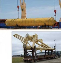
Buoyancy can
A nitrogen-filled buoyancy can holds the riser system’s vertical section in the proper orientation. The BC is cylindrical, 34.2 m long, 5.45 m in diameter, and fabricated from 50,000-psi yield material. Bulkheads separate 15 of the 16 2.28-m tall compartments. The BC’s design is pressure balanced, with the internal pressure slightly above the external pressure of water, resulting in a ½-in. thick skin. A 56-in. outer diameter central stem, the 16th compartment, runs along the BC’s longitudinal axis.
Ports on the side of each compartment dewater the BC. Each compartment features an inlet and an outlet port. Injecting nitrogen into the BC at pressure for dewatering leads the BC compartment to be slightly overpressurized with regard to the water pressure outside.
The BC design leaves at least one of the 16 compartments permanently water-filled as a contingency. Should one compartment fail in service, a contingency compartment can be dewatered to keep operational tension in the riser string.
Tether chain
A tether chain connects the BC to the top of the vertical riser. Including universal joints at each end of the chain reduces bending moment. The lower part of the chain includes the load monitoring spool, used for measuring the tension provided by the BC. A hydraulic connector links the chain’s lower end to the top riser assembly.
Top-riser assembly
The top riser assembly consists of a truss-type structure providing connection to the flexible jumper and the tether chain. The TRA uses a 2,200 mm bend radius spool (>3 diameters), designed to allow vertical connection of the flexible jumper. It has three main forged components. Fig. 3 shows the BC and TRA assemblies.
null
Stress joints
The taper stress joints are high-specification forged carbon steel components fabricated from 80,000 psi yield-strength material designed to control the bending at the base and top of the riser. They have a linearly varying WT and a profile optimized to withstand both extreme loads and long-term fatigue loading.
A flange at both stress joint bases connects the TRA and offtake spool. Pup pieces connect the UASJ and LASJ to the riser’s standard joints, avoiding an offshore weld directly to the tapered joints.
Lower-riser assembly
The lower part of the FSHR, above the foundation, consists of three components: the offtake spool, the LTSJ, and the LASJ. The assembly connects with the seabed foundation at the bottom and the upper pup piece at the top. The offtake spool is a cylindrical forged component. The spool contains a flow path traveling through its top and exiting from the side via an offtake. The offtake includes an upward facing mandrel for connecting the RBJ.
Foundation
The FSHR foundation consists of a drilled and grouted 36-in. OD conductor installed by P-23, a MODU owned by Petrobras. The conductor is 120 m long, with the 12 m long segments joined by Merlin connectors. The first five joints from the top are 2-in. WT X-80 pipe, while the remaining joints are 1.5-in WT X-60. Design considered two cement shortfall cases: at 0 and 25 m from the mud line. Conductor verticality installation tolerance was 1° of vertical axis, any direction. A modified drilling base installed on top of the conductor pulled down the FSHR during deployment.
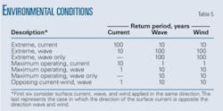
Table 5 presents environmental conditions used for the connected FSHR global analysis.
FSHR design
The overall philosophy for the definition of load cases follows the format adopted by API RP 2RD and considers test, operating, extreme, and survival load categories. Within each category a number of separate load cases exist, each having various combinations of environmental conditions, pressures, and platform offsets. Environmental events occuring across a range of directions required a number of load cases to assess component response. Platform offsets applied in various directions ensured all worst-case loads were covered.
P-52 offsets
Design maximum static offsets measure 5% water depth for the intact mooring system and 7.5% water depth with one mooring line broken but depend on the direction of environmental action. Offset also considered FSHR foundation and P-52 installation tolerances.
Fatigue criteria
The acceptance criterion for fatigue damage = [(installation fatigue damage) + (in-place fatigue damage in 25 years)] × 10 <1.0. Vortex-induced vibrations (VIV) include long-term and storm current profiles (1, 10, and 100 years return period).
Sensitivity analysis
Sensitivity analysis determined the effects of practical variations in riser configuration with time and uncertainties in design parameters. Parameters considered include:
- Hydrodynamic drag coefficient (e.g., Reynolds number, pipe and buoyancy-can roughness, and any amplification due to riser VIV & BC vortex-induced motions).
- Components’ weight tolerances.
- Components’ installation tolerances.
Riser models incorporated the expected extremes from these parameters. Analysis of previously identified critical load cases quantified parameter changes’ effects on response.
Vortex-induced motions
With no strake around the BC, potential fatigue damage with the FSHR system also considered dynamic effects of vortex-induced motions (VIM) from current profiles. Applying the sinusoidal VIM amplitudes (in-line and cross flow) with the associated vortex-shedding periods to the buoyancy can’s center of gravity allowed assessment of the induced bending stress ranges within the riser string (including the TRA), chain links, universal joints, gooseneck, taper joints, etc. It also estimates the fatigue damage and the load and motion histograms of each riser component.
This methodology performed the FSHR fatigue analysis induced by BC VIM due to 87 long-term current profiles and 24 extreme current profiles.
The primary motion of a BC under current is perpendicular or transverse to the current directions (crossflow), while the secondary motion is in-line with the current. Together, these trace a figure eight in the horizontal plane. The in-line amplitude is smaller than the cross-flow amplitude, but occurs at twice the frequency of the later.
A conservative approach considered for the full range of current velocities acting on the BC included: cross-flow single amplitude ratio A/D = 1 and in-line single amplitude ratio A/D = 0.2; D = BC diameter, A = single amplitude.
FSHR design
The design of an FSHR typically involves an up-front global analysis of the system to optimize riser configuration. Variable parameters include offset from the production platform, depth of BC, flexible jumper length, net upthrust provided by the BC, and flexible jumper azimuth. Clearance may beecome an issue and interference with adjacent risers or mooring lines drives the choice of the system layout.
Global storm and fatigue analyses to define functional loadings on the critical riser components, as well as stress concentration factor (SCF) requirements, follow selection of the system configuration. API RP 2RD guided riser string design and analysis, while TRA design used API RP 2A-WSD. The 18-in. OD piping components in the TRA used ASME B31.4.
Riser response
Since the riser and buoyancy can lie away from the wave zone and surface currents, direct wave loading on the system is low. The flexible jumper connecting the vertical section of the riser to the floating production unit decouples riser motions from vessel excursions and first order motions. Current and vessel offset drive riser response, causing increased loading in the gooseneck and also at the riser’s lower end. Local strengthening of the components, however, can address this increased loading.
At both ends of the flexible jumper, bend stiffeners keep the curvatures of the flexible pipe within allowable limits. Plots of typical bending moment distribution along the riser’s length in extreme storm conditions show two peaks; one at the riser base, the other at the interface with the TRA. Large bending loads are present at both ends of the riser, but special components such as taper joints control the curvature and stress, bringing the stress ratios at the ends lower than those found at the riser standard joints.
The free-hanging flexible jumper load case proved important due to the high loads and stresses caused by this survival condition. Sensitivity analysis showed hydrodynamic drag amplification due to VIV inducing higher loadings (shear forces, bending moments, von Mises stress) at the riser base. No clashes exist between the FSHR system and adjacent lines (mooring line No. 16 and the 7-in. production flexible riser) for the load cases considered.
There were also no clashes between the FSHR flexible jumper and the P-52 hull during both intact and damaged-pontoon conditions for the load cases considered. Sensitivity analysis shows the parameters studied to have no impact on minimum clearance.
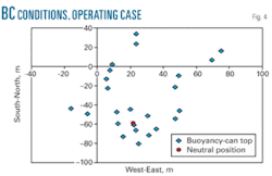
Fig. 4 shows the positions of the BC’s top in the horizontal plane for 24 load cases (Operating Design Case 1). The foundation position is (0,0). Fig. 5 also shows the BC’s position in the neutral position load case (FJ installed, system subject to only gravity and buoyancy loads).
Acknowledgment
The authors thank Petrobras management for clearance to publish this work.
The authors

Francisco E. Roveri ([email protected]) is a consultant engineer at the subsea technology group of Petrobras R&D Center, Rio de Janeiro. He has worked for Petrobras for 30 years. He holds an MS (1985) from Federal University of Rio de Janeiro.

A.G. Velten Filho ([email protected]) is an equipment engineer at the subsea services department of Petrobras, Rio de Janeiro. He has worked for Petrobras since 2004. He holds a mechanical engineer degree from Federal University of Minas Gerais (1998) and a postgraduate degree in petroleum engineering from PUC-RJ.

V.C. Mello ([email protected]) is a contract manager of subsea pipeline projects in the engineering department of Petrobras, Rio de Janeiro. He has worked for Petrobras since 2004. He holds an MS (2004) from Federal University of Rio de Janeiro.

L.F. Marques ([email protected]) is a project manager of the subsea services department of Petrobras, Rio de Janeiro. He has worked for Petrobras for 29 years. Main activities include offshore platform and module installation, pipeline design and installation, and project management. He holds a mechanical engineering degree from PUC-RJ and an MBA from Federal University of Rio de Janeiro.
Correction
In the article “Natural gas pipeline profits surge; oil flat,” by Christopher E. Smith, the Oil Pipelines table (OGJ, Sept. 1, 2008, pp. 65-67) contained errors. Following are corrected versions of the affected portions of the table. The corresponding data have also been updated in the OGJ Energy Database.
Pioneer Pipe Line Co.
MILES
Gathering: --
Crude: --
Products: 563
Total: 563
DELIVERIES (‘000 bbl)
Crude: --
Products: 24,806
Total: 24,806
TRAFFIC (million bbl-miles)
Crude: --
Products: 5,162
Total: 5,162
FISCAL ($1,000)
Carrier property: 90,259
Property change: 384
Operating revenue: 23,711
Income: 7,865
2007 totals:
MILES:
Gathering: 14,911
Crude: 46,658
Products: 85,883
Total: 147,452
DELIVERIES (‘000 bbl)
Crude: 7,038,083
Products: 6,893,484
Total: 13,931,567
TRAFFIC (million bbl-miles)
Crude: 1,451,245
Products: 2,007,310
Total: 3,458,555
FISCAL: ($1,000)
Carrier property: $35,863,217
Property change: $4,061,205
Operating revenue: $8,993,696
Income: $3,755,352