Contaminants key to refinery offgas treatment unit design
This article details methods for removing individual contaminants in refinery offgas (ROG). Various configurations of the ROG treatment unit and associated units are compared, depending on the type of product and feedstock. This article also discusses optimization strategies required for design of ROG treatment units.
ROG is produced in refinery units such as hydrotreaters, alkylation units, FCCs, and catalytic reformers, that manufacture conversion products. Refiners can recover valuable products including hydrogen, olefins, NGLs, and higher-btu fuel gas from the offgas if an ROG unit is installed. Incremental economics of product recovery as opposed to using the entire offgas for fuel provides incentives for installation of ROG units.
Specifications of recovered products and catalyst requirements will dictate the allowable limits of these contaminants in the feed stream.
Refinery offgas
Investment incentives for installation of ROG processing units are the incremental economics for production of hydrogen, olefins, NGLs, and higher-btu fuel gas as opposed to using the entire offgas stream for fuel. Added value from the liquids recovered in the offgas processing unit will normally be the largest profit source.
If a refiner can produce a hydrogen stream that is of sufficient purity and at the appropriate battery-limit conditions, then production of this hydrogen will normally have reasonable economic benefits compared to production of hydrogen from standalone plants. If the refinery is near an ethylene plant, recovery of products such as ethylene and propylene for petrochemicals can boost profitability while corecovering hydrogen through refinery and petrochemical integration.
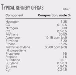
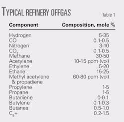
Table 1 shows the composition of a typical ROG stream. The stream’s hydrogen content varies appreciably depending on the source. The heavier liquid components (C2+) also vary considerably, between 20% and 40%.
An ROG stream can contain many trace components such as oxygen, ammonia, nitriles, acetylenes, heavy sulfur compounds, butadiene, chlorides, arsenic, mercury, and water, in addition to the acid gases H2S, CO2, and COS. Removal of certain contaminants in feed pretreatment is essential.
Several contaminants that may be present in the ROG can cause significant problems in the cryogenic section. These include diolefins, NOx, mercury, CO2, water, and some sulfur compounds. The presence of these compounds will require front-end treating for ROG processes with cryogenic units to meet product specifications.
ROG unit products
Products from an ROG unit typically include a hydrogen-rich gas, a methane-rich gas, and an NGL stream. Installation of an ROG unit is beneficial for refiners because the main polluting components from the offgas are separated and value-added products, like hydrogen-rich gas and NGL, are produced. Burning of methane-rich gas without polluting and soot-forming components is also beneficial environmentally.
The cryogenic section produces a hydrogen gas that meets the required purity; or a higher purity if it is further purified in a PSA unit. Recovered NGLs are normally fractionated to produce a mixed C2 and C3+ stream.
The C2 stream can be further fractionated to produce a polymer-grade ethylene and ethane product. The C3+ stream may be split into a propylene product and a propane product depending on the economics.
The propylene can be either polymer grade (99.5 mole % propylene) or chemical grade (93-95 mole % propylene). Generally speaking, it is uneconomical to produce polymer-grade propylene based on the mixed C3 compositions in typical ROG streams. Production of polymer-grade propylene may be an option contingent on the local market.
ROG units typically feed 25-120 MMscfd of gas. Generally, the compression and cryogenic recovery sections are the most costly and energy intensive depending on the feed treatment requirements.
Designers of ROG plants attempt to maximize NGL recovery and impurity tolerance to reduce the capital cost of front-end treatment. If saturated gas from the refinery, for example, has sulfur compounds and CO2 as its main impurities, the ROG unit can be designed to remove most of the sulfur and C4+ compounds in the first stage of chilling and the NGL-recovery unit can be a CO2-tolerant design. The C4+ can return to the refinery with the sulfur compounds because they may go to a Merox unit or refinery hydrotreater.
ROG unit configuration
A refinery offgas plant generally consists of the following sections:
- Feed compression and front-end gas treatment.
- Cryogenic separation of H2, methane, and C2+.
- Hydrogen purification.
- Fractionation of the C2+ components.
A refiner selects the process scheme for front-end, feed gas treatment based on the types and levels of contaminants, as well as the allowable levels of contaminants in the final products.1 2 The process scheme for the cryogenic section is based on many factors including feed-gas pressure, hydrogen product purity, unit cost of electricity, and desired recovery level of the C2+ fraction.
Available options for hydrogen purification include cryogenic separation, membrane separation, and pressure swing adsorption (PSA).3 4
The process scheme for fractionation of the C2+ fraction depends on the desired product slate and product specifications.
The ROG unit’s design should give due consideration to the feed-gas composition from the refinery based on future expansion and modification plans. Upset conditions and off-design cases can also influence drastically ROG unit operations. These conditions can include increased concentration of sulfur compounds and a greater or lesser concentration of hydrogen in the feed gas.
If the hydrogen concentration in the feed gas drops over the time, for example, a membrane type unit may not be the most economical choice. A lower feed hydrogen concentration means that hydrogen removal can be accomplished more economically in a cryogenic unit followed by a PSA unit.
A feed profiling study is therefore important for the most optimal design.
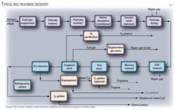
The figure shows a schematic block flow diagram of a typical ROG recovery plant with deep recovery of hydrogen and C2s.
Process design
Important factors in the design of an ROG unit include inlet gas compression, front-end feed treatment, cryogenics, fractionation, and refrigeration.
Inlet gas compression
ROG is usually delivered to the battery limits at a low pressure (50-250 psig). The gas is then compressed to the required pressure, normally with two compression stages. Reciprocating compressors accommodate sudden changes in feed flow rate and molecular weight. Feed gas should be compressed to a higher pressure consistent with that required for the targeted cryogenic liquid recovery.
The compression section is normally one of the most cost and energy-intensive sections, and the design difficulty lies in optimizing this section. The type and number of compressors, in addition to the efficiency of their drivers, are important design considerations. If a recycle compressor is required, for example, the design should consider centrifugal machines for this service.
The designers should conduct a reliability and maintainability study to evaluate plant availability and determine any sparing requirements.
Front-end feed treatment
Due to the different process sources of ROG, impurities encountered in the stream may include water, H2S, CO2, COS, methyl mercaptan, acetylene, methyl acetylene, mercury, HCl, organic chlorides, oxygen, CO, NOx, ammonia, and stibine.
Impurities are normally present in various concentrations. Removal of these compounds is required for:
- Safety.
- Corrosion control.
- Product specifications.
- Prevention of freezing in the plant’s cold section.
- Prevention of catalyst poisoning in downstream facilities.
- Compliance with environmental requirements.
Selection of the treating processes will depend on the types and quantities of feed impurities. Various catalysts and chemicals are required for the treating processes. Catalyst loading and chemical consumption are important for ROG recovery. Performance data from vendors are needed to determine the catalysts required and size of equipment.
Generally, front-end treatment is preferred particularly when the contaminants such as mercury and chlorides, water and CO2, or NOx and oxygen, can corrode equipment and materials of construction, cause operational problems like freezing in the cryogenic section, or reduce safety of the unit, respectively.1
Treating the entire ROG feed at the unit’s front end or treating the fractionated products individually to meet the finished product specifications at the back end are options to remove contaminants such as acetylenes or sulfur compounds.
For acetylenes, feed concentration is key to the relative location of the acetylene converter in the process scheme. With low acetylene concentrations, front-end hydrogenation of acetylene is preferred. With high acetylene concentrations, back-end hydrogenation with a selective palladium catalyst is preferred.5
This article assumes front-end treatment of the offgas and removal of all contaminants.
Chloride removal
Gas from the compressor discharge feeds a chloride guard bed, which removes chlorides. Chlorides can take the form of hydrogen chloride and various organic chloride compounds. Chlorides are present because they are used to condition catalytic reforming catalysts.
Chlorides can act as a poison to the nickel-based catalyst that is required for conversion of acetylene and oxygen. They must therefore be removed beforehand.
Other types of problems due to chloride include chloride-induced corrosion, formation and deposition of ammonium chloride, and off-spec products.6 The type of chloride in the feed will determine the method for chloride removal.
Activated alumina or promoted alumina can remove HCl but not organic chlorides. Catalyst manufacturers are currently developing adsorbents that can remove organic chlorides. Selective hydrogenation of chlorides in the presence of olefinic components in the ROG is generally not an option.
Selective hydrogenation
The figure shows that feed gas flows from the chloride bed to the feed-gas treater, which is a selective hydrogenation unit. A nickel-based sulfided catalyst, such as Sud-Chemie’s C-36, can be used for front-end feed gas treating.
This catalyst was developed to treat FCC offgas. It is a multi-functional catalyst that removes or converts many kinds of poisons and impurities to low levels, including oxygen, NOx, acetylene, methyl acetylene, butadiene, arsine, phosphine, stibine, and mercury.
The nickel-based sulfided catalyst can treat:
- Oxygen. This promotes polymeric formation of light olefins and can react with amines to form carboxylic acids, which crystallize at low temperatures. It can also react with H2S to form sulfur at high temperatures. Furthermore, it may be a major factor in the formation of NOx. It is therefore important to remove oxygen completely from the feed before it enters the cold box to avoid cold box plugging.
- Acetylene. This is a catalyst poison for olefin polymerization. It can also promote coking. The typical product specification for polymer-grade ethylene requires concentrations of oxygen and acetylene of less than 1 ppm (vol).
- NOx. This forms in FCC units during spent-catalyst regeneration. When reacting with oxygen, NO will form NO2 at low temperatures. NO2 accumulates as a solid in cold sections of the plant. Further reaction of NO2 with oxygen will lead to formation of N2O3 or “blue ice.” The N2O3 freezing point is –152° F.
NO2 or N2O3 may react with diolefins to form an unstable gum, which can explode when exposed to a sudden warm-up of the plant. N2O3 can also react with ammonia to form ammonium nitrate that can explode at warm temperature. NOx is converted to ammonia by the sulfided nickel catalyst that is used in the front end acetylene converter. - Nitriles. Catalyst companies claim that nearly all nitriles are converted to amines using the sulfided nickel catalyst. This claim, however, is unproven and a conservative design for the process assumes no conversion. Molecular sieve adsorption of the offgas feed is the recommended method for removal of these nitrogen compounds if they are present.
Acid-gas removal
After leaving the selective hydrogenation reactor, gas flows through an acid-gas removal system. This system can be an amine unit followed by caustic treating or a stand-alone caustic treating system.
Caustic
Product specification of polymer-grade ethylene recovered from the ROG gas requires a total sulfur level of less than 1 ppm (wt). A caustic wash is required to remove sulfur compounds to required levels.
Feed gas from either the selective hydrogenation bed or amine treater feeds the caustic tower. For ethylene plants, a two- or three-stage caustic tower is normally used. Typical caustic concentrations are 11 wt % for the upper stage and 3 wt % for the lower stage.
Caustic systems require less capital than amine systems, but the operating costs are higher due to caustic use.7 8 Amine units do not remove mercaptans to a significant extent. A caustic wash system is required if mercaptans are present. The design must also consider disposal of acid gas from the amine unit.
Inlet gas dehydration
After acid-gas removal, the gas must be dehydrated so that hydrates will not form in the downstream cryogenic unit. Temperatures in the cryogenic unit can be as low as –256° F. Because olefins are present, 3A molecular sieve is normally used. This type of molecular sieve was developed specifically for cracked gas drying and will adsorb only water.
Because refrigeration is available, the design should consider chilling the feed gas from the caustic tower overhead to feed the dehydrators. This will reduce the size of the dehydrators and lower regeneration gas requirements. The gas can be chilled to 5-10° F. above the anticipated hydrate point.
COS removal
Amines or caustic do not remove COS effectively. The recommended method is a bed of alumina adsorbent, which is normally upstream of the mercury-removal bed and downstream of the dehydrators.
Alternatively, the COS-removal unit can be upstream of the amine-caustic system and designed as a COS hydrolysis unit. The fixed-bed catalytic reactor converts COS to H2S and CO2, which can then be removed in a downstream amine unit.
Mercury removal
The designer should assume that mercury is present unless tests ascertain otherwise. A mercury guard bed captures mercury and protects downstream brazed-aluminum exchangers. A sulfur-impregnated activated carbon can be used for this service. Zinc and copper-based chemical adsorbents can also be used.
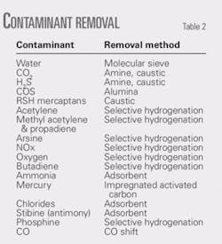
Table 2 shows a summary of ROG feed contaminants and the pertinent removal method.
Cryogenic section
Cryogenic separation is the core of the ROG liquids-recovery process. A typical process involves a series of progressive cooling in plate-fin heat exchangers and vapor-liquid separation steps, followed by demethanization.
Mechanical refrigeration is required in the cryogenic unit to reach the temperatures required for desired NGL recovery and to meet required hydrogen purity. Turboexpanders can be used in combination with external refrigeration to increase thermodynamic efficiency of the process. Expander-based liquids recovery is commonly used.
A cryogenics unit produces three product streams from the ROG unit:
- C2+ liquids to feed the downstream fractionation unit.
- Methane-rich offgas for fuel.
- Hydrogen-rich offgas for further purification.
The cold box includes several stages of cooling in plate-fin heat exchangers. A cryogenic unit can produce a moderately pure hydrogen stream of around 95 mole %. The hydrogen-rich stream from the cold box can be purified to 99.9% in a PSA unit, which also produces a low-btu offgas stream.
If CO is present in the high-purity hydrogen from the PSA unit, the stream can be treated in a methanator for conversion of CO, followed by dehydration in hydrogen dryer.
The cryogenic unit’s demethanizer fractionates methane gas from NGL product according to battery-limits product specifications. Depending on the cryogenic processing scheme used, the demethanizer overhead can feed a PSA unit for hydrogen purification or to the fuel gas system. The demethanizer will normally have several feeds and side reboilers for heat integration.
Fractionation
The fractionation train configuration and complexity depends on the types of products required. The fractionation train normally includes a de-ethanizer, a depropanizer, a C2 splitter, and an optional C3 splitter.
Product specifications determine the columns’ design parameters:
- The depropanizer can produce refinery-grade propylene.
- The C2 splitter can produce polymer-grade ethylene.
- The C3 splitter separates a mixed C3 stream into chemical-grade propylene and commercial-grade propane.
Propane refrigeration is used for the de-ethanizer and C2 splitter condensers.
The demethanizer bottoms stream enters the de-ethanizer at the midsection. The de-ethanizer normally operates at about 390 psia at the overhead.
Low-pressure steam provides heat in a thermosyphon reboiler. Refrigerant from a propylene refrigeration system condenses overhead vapors.
The de-ethanizer bottoms, consisting of propylene, propane, and heavier components, feed the depropanizer. De-ethanizer overhead is a mixture of ethylene and ethane. It feeds the C2 splitter.
Ethane product from the C2 splitter bottoms goes to the product surge drum. Both ethylene and propylene products are pumped from the product drums, heated, and delivered to pipelines.
The depropanizer operates at 285 psia, which allows cooling water to condense overhead vapors. Low-pressure steam provides reboil heat to the column.
C4+ product from depropanizer bottom feeds the product pipeline. The overhead product, refinery-grade propylene, is withdrawn from the reflux drum and pumped to a pipeline. Alternately, if required, refinery-grade propylene (mixed C3s) can be further fractionated to propane and chemical-grade propylene in a C3 splitter.
Overhead chemical-grade propylene is withdrawn from the C3 splitter reflux accumulator and pumped to the propylene storage tank for pipeline delivery. The bottoms propane product from the C3 splitter feeds the propane product surge drum where it is pumped to pipeline pressure for delivery.
Refrigeration
Two refrigeration systems are needed for a typical ROG plant. One system is propylene (or propane) for feed prechilling and overhead condensers in the fractionators. The other system, which provides a colder level of refrigeration for the cold box, can be cascaded ethylene refrigeration or a mixed-refrigerant system.
Acknowledgment
This paper is dedicated to the memory of Thomas J. Kenney, who contributed to this paper at Technip USA prior to his passing in late 2005.
References
Based on a presentation to the 2008 National Petrochemical & Refiners Association Annual Meeting, Mar. 9-11, 2008, San Diego.
The authors
Sheng-Yi Chuang is a staff technologist for Technip USA Inc., Houston. He has more than 30 years’ experience in process engineering and design in the LNG, gas processing, and petrochemical industries. Chuang holds a BS from National Taiwan University and a PhD from Rice University, both in chemical engineering.
Rajeev Nanda is a process manager, gas processing, LNG, and offshore for Technip USA Inc., Houston. He has more than 20 years’ experience in the oil and gas industry and has been involved in several large-scale projects from conceptual design through commissioning. Nanda is part of Technip’s global expert network for gas processing and LNG regasification. He holds a BS in chemical engineering from Harcourt Butler Technological Institute, India, and an MS in process design and engineering from Indian Institute of Technology, New Delhi. He is a member of AIChE.
John Rizopoulos ([email protected]) is vice-president of process engineering for Technip USA Inc., Houston. He has 25 years’ experience in the engineering, procurement, and construction industry. Rizopoulos holds a BASc in chemical engineering from University of Windsor, Canada. He is a registered professional engineer in British Columbia, Alberta, Ontario, and Texas.


