Corrosion problems solved in CT nitrogen operations off Brazil
Laboratory and field research with various completion fluids helps refine procedures to reduce corrosion in coiled tubing during use of nitrogen contaminated with oxygen.
For several years, coiled-tubing operations off Brazil have used nitrogen generation units. Petrobras has increased the use of nitrogen generation units because of the remote locations, lack of liquid nitrogen suppliers, and other logistical issues.
Using a nitrogen generation unit in remote locations, where most of the platforms have very limited space, solved the longstanding problem of supplying nitrogen. However, when we used a nitrogen generation unit with coiled-tubing operations, another concern arose.
In situ nitrogen generation does not produce pure (99.9%) nitrogen gas. In situ nitrogen generation can yield nitrogen gas compositions with oxygen content as high as 5%.
Under downhole conditions, using nitrogen with the oxygen content as high as 5% can result in severe corrosion in the coiled-tubing (CT) string. Furthermore, completion brines and acids are sometimes pumped, increasing the corrosivity downhole.
Occasionally operations were stopped because the coiled-tubing bottomhole assembly (BHA) was either completely plugged by oxidized metal flakes or the coiled-tubing string became so corroded that it required inspection before further use. Based on these corrosion and safety issues the use of in-situ nitrogen generation loses its benefits.
To find a solution to this corrosion problem, we undertook a laboratory research study with the most commonly used CT string material, then pumped treatment fluids under surface and downhole conditions with the maximum percentage of oxygen concentration expected in operations. We tested several corrosion inhibitors and mixtures for their ability to control corrosion.
After laboratory testing established which inhibitor systems would control the corrosion rate of the CT, yard tests confirmed that the inhibitor would work in the field. Following successful field trials, we changed the recommended practices to avoid corrosion problems when nitrogen generation units are used offshore.
This article presents the development of this project, beginning with CT corrosion observed in laboratory research studies, yard trials, recommended field applications, and applying the results in live operations on the Merluza platform in the Santos basin.
Nitrogen workovers
Cleaning out depleted vertical wells by removing sand and other debris, and pumping acid stimulation treatments into specific zones is a common application for coiled tubing. Treating depleted wells generally requires nitrogen be added to the workover fluid. This ensures that the hydrostatic pressure stays below the reservoir pressure.
One of the disadvantages of using a nitrogen generation unit is that it can generate as much as 5% oxygen along with the nitrogen. According to corrosion literature and experience, an oxygen level of 5% is sufficient to create corrosion in the presence of chloride completion brine systems and acidic fluid systems.
In one example, CT operations were stopped because the BHA of the coiled tubing was completely plugged. Later observation of the coiled tubing found severe corrosion that could have resulted in pipe failure.
Corrosion
Corrosion processes are heterogeneous electrochemical reactions that generally occur on metal surfaces in corrosive environments.
These oxidation-reduction reactions involve transferring electrons. Corrosion processes can be considered metal oxidation reactions, which means that metals act as reductors, donating electrons that are received by an oxidant. Corrosion is a method by which the metal material is degraded, due to electrons being lost at the surface.
Corrosion occurs through different mechanisms. For each mechanism, the process is complex, incorporates many factors, and varies according to the metal and the specific operating conditions. Corrosion types are classified by:
- Morphology.
- Mechanism.
- Mechanical factors.
- Environment.
- Attack localization.
Characterization according to morphology helps to clarify the mechanism and adequate application of protection. Based on morphology, the main classification, the general types of corrosion are:
- Generalized or uniform.
- Plaques.
- Pitting.
- Intergranular.
- Transgranular.
- Filiform.
- Exfoliation.
Uniform corrosion
Uniform corrosion normally occurs on metallic surfaces where the homogeneous composition and microstructure are in uniform contact with the corrosion environment.
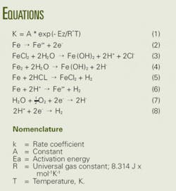
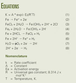
At elevated temperatures, the attack is generally accelerated. The relationship between corrosion rate and temperature follows Arrhenius´ equation (Equation 1), which affirms that an increase of 50º F. redoubles exponentially the increase in the rate of the chemical reactions.
At higher temperatures, the higher collision rate of molecules, due to the higher kinetic energy, affects the activation energy of the reaction. The activation energy is the amount of energy required to initiate a reaction. In aqueous solutions, the temperature increase can reduce the oxygen proportion and, therefore, the corrosion.
This is the only form of corrosion for which metal loss, or weight loss, data from corrosion coupons or ultrasonic testing can be used to accurately and reliably estimate corrosion rates and pipe’s life expectancy.
Observed corrosion
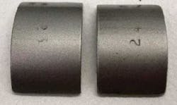
Generalized corrosion inside the CT string was the type observed in this field study. This type of corrosion is well distributed across the entire metal surface, with little or no localized penetration. It is the least damaging of all corrosion types. However, during operations in which fluids were pumped through the coiled tubing after rust had formed, the BHA became completely plugged. Therefore, the coiled-tubing operations were stopped with economic repercussions. Fig. 1 shows a picture of the CT string before use in the field and after the pipe had been used in a field operation with generated nitrogen containing a maximum of 5% oxygen.
In this case, we observed uniform corrosion, as well as pitting, primarily because brines and acid blends were commonly used in this CT operation. Although pitting affects only small portions of the metal surface, pitting can cause a quicker loss of wall thickness and result in crevices, perforations, and stress concentration points. These pits reduce the material’s mechanical resistance and can result in a fracture of the pipe or a coiled-tubing failure.
The presence of chlorides in a corrosive environment accelerates pitting corrosion. Pitting corrosion is initially slow. However, once pits are formed, this autocatalytic reaction can be self-sustaining in CT as the chromium tends to provide a strong potential for the corrosion cell to continue to grow.
In the anodic area, steel oxidation produces pitting, forming Fe+2, Cr+2, and Ni+2 ions. Equation 2 illustrates this, using iron as an example.
This generates an excess positive charge and causes the migration of chloride ions (which have a higher mobility than OH- ions) inside the pitting to compensate for the charge. Consequently, this causes an increase in salt concentration, FeCl2. This salt undergoes hydrolysis, creating hydrochloric acid, HCl (H+ + Cl-), as shown in Equations 3 and 4.
The increase in ions (H+), means the pH drops, which accelerates the corrosion process because the formed HCl begins to attack the metal, as shown in Equations 5 and 6.
With the consequent formation of FeCl2+, which will again undergo hydrolysis according to Equation 3, the continuity of the corrosion process is assured. Because oxygen practically has no solubility in salt-concentrated aqueous solutions, there is no oxygen reduction inside the pitting according to the reaction shown in Equations 7 and 8.
Laboratory testing
BJ Services conducted laboratory corrosion studies to determine the effectiveness of different corrosion inhibitors in adequately protecting coiled-tubing steel from the uniform and pitting corrosion previously described. Membrane gas generated in-situ creates the corrosive environment, a common situation for CT operations offshore Brazil.
Table 1 shows the specifications of the coiled-tubing steel, which is modified from ASTM A-606 Type 4 high-strength, low-alloy (HSLA) steel. It is designed to corrode uniformly under atmospheric conditions and self-passivate. It is the most common CT material in the Campos basin.
Fluids. The fluids used in the tests were the most commonly pumped fluid systems in CT jobs in the referenced area: 3% KCl brine and 5% acetic acid + 7% formic acid
Gas mixture. Due to the corrosion problems observed during use of the generated nitrogen with 5% oxygen (O2) content in the field, this gas mixture was used in all corrosion studies. Under standard conditions, the units available at the field produce 750 scf/min at 95% nitrogen (N2) purity (<5% O2).
Corrosion inhibitors. Ten different corrosion inhibitors (CI) were tested, as were blends among them. Experiments were run with and without corrosion inhibitors.
The following lists and describes the corrosion inhibitor codes:
- CI-1 = Imidazoline-ethoxylated alkyl ether phosphate organic corrosion inhibitor.
- CI-2 = Corrosion inhibitor blend of naphthalene and ethyl benzene (organic blend).
- CI-3 = Cationic organic acid corrosion in inhibitor.
- CI-4 = Corrosion inhibitor blend of imidazolines, surfactants, and organic acids.
- CI-5 = Oil-based solvent.
- CI-6 = Oxygen high-shear, high-temperature organic corrosion inhibitor.
- CI-7 = Acid corrosion inhibitor blend of alcohols and solvents.
- CI-8 = Acid corrosion inhibitor blend of alcohols and quaternary derivatives.
- CI-9 = Quaternary amine polymers.
- CI-10 = Phosphonate iron chelating agent.
Simulation of downhole conditions. Static corrosion studies were conducted in a 95% nitrogen-5% oxygen environment at the temperature of 230° F., and a pressure of 400 psi, under two different exposure conditions:
- A wet surface area of the corrosion coupon only from dipping in the test fluid.
- The metal coupon totally immersed in the test fluid for the entire corrosion study period.
This environment was created with an Ofite HPHT filter press.
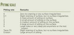
Measuring results. We measured test results both quantitatively and qualitatively. Corrosion rates were measured in mils/year (mpy) and lbm/sqft/time; the pitting rating was reported according to the scale in the accompanying box.
Experiment description
We conducted corrosion studies with the 3% KCl brine and the metal coupons using several different corrosion inhibitors. With each corrosion inhibitor and inhibitor blends, one coiled-tubing coupon was dipped twice into 3% KCl brine containing the inhibitor and placed into the Teflon cup inside the corrosion bomb with no fluid sample present.
In the second test with each corrosion inhibitor, we added the 3% KCl with inhibitor fluid to the Teflon cup and placed the steel test coupon into the fluid for the entire corrosion incubation period. We allowed the corrosion tests with the 3% KCl brine and the steel test coupon to run for an 18-hr incubation period at 230° F.
We also conducted corrosion studies with the 5% acetic-7% formic acid system over a 6-hr exposure period. As in the KCl corrosion studies, we dipped one coupon twice in the inhibited acid and placed it in the Teflon cup with no fluid for the entire corrosion study period.
In the second set of corrosion tests with the inhibited acid, we placed the coupon in the inhibited acid fluid volume for the entire 6-hr incubation period.
After each steel coupon was placed in its respective corrosion cell, the cell was closed and evacuated with nitrogen gas three times to insure that all the atmospheric air had been purged. After the third nitrogen evacuation, we pressurized each corrosion cell to 400 psi with a 95% nitrogen and 5% oxygen gas mixture to simulate the nitrogen atmosphere in the field. Each corrosion cell was placed in a 230° F. oven for the test incubation period.
After the incubation period, the cells were cooled and the pressure released. We removed each test coupon from the cell, neutralized it with soda ash, and washed with water. The test coupons were photographed to record their surface condition before being sandblasted, cleaned, dried, weighed, and their surfaces evaluated for pitting. We compared the final weights to the initial weights of the coupons to determine the corrosion rates for each fluid environment.
Laboratory corrosion studies
We conducted tests on ten different corrosion inhibitors and blends, recording corrosion and pitting rates.
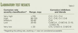
Table 2 shows the classified results according to the severity of corrosion observed. This table was used to select the corrosion inhibitors that would be tested in the field.
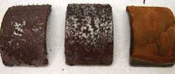
Tables 3 and 4 provide more detail of the inhibitors’ concentrations, blends, and results. Figs. 1-5 show the coupon samples with varying amounts of corrosion.
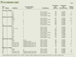
Table 3 details test results for the 3% KCl brine, at 230° F. in 95% nitrogen and 5% oxygen environment, at 400 psi, in a static corrosion cell for a period of 18 hr.
Table 4 gives the results for 5% acetic acid-7% formic acid, tested at 230° F. in 95% nitrogen and 5% oxygen environment, at 400 psi, in a static corrosion cell for a period of 6 hr.
Based on the laboratory corrosion results, the next step was to select the best-performing corrosion inhibitors and to test its application in the field.
Yard tests were recommended to define injection rates that would fulfill operational limitations, such as offshore product storage, while providing the desired pipe protection.
Yard, field trials
We developed new operating procedures for injecting corrosion inhibitors (CI) into the system while pumping generated nitrogen.
First, it is important to understand the final purpose of the in-situ generated nitrogen use in CT operations. In some cases, only nitrogen is pumped through the CT string to reduce the hydrostatic pressure applied downhole by the fluid inside the well and, thereby, bring the well back on production. In the other cases, fluid is commingled with nitrogen, to clean the well, perform a stimulation treatment, or activate tools such as rotational jetting tools or downhole motors. For these situations, the most commonly selected fluids are brines, gels, diesel, or acids. These were the scenarios tested in the laboratory, yard, and field.
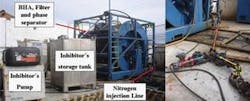
Fig. 6 shows the yard test equipment rig up, with details of the components. While generated nitrogen was pumped through the string, corrosion inhibitor was dosed to create an internal film that would protect the pipe from corrosion.
Several CI injection rates were tested until the appropriate protection was established for both high- and low-N2 generation situations. The corrosion inhibitor that performed the best was CI-5. Because this was not a blended product, it was the best choice from an operational point of view being: easy to handle, non-toxic, readily available locally, and economically feasible.
Table 5 shows the observed parameters.
In order to give time for rust to form, the test was performed continuously for 3 days in both cases, the string was pickled with 5 bbl of 5% HCl with the BHA still in place. We removed the BHA afterwards for inspection.
As seen in Figs. 7 and 8, only a small amount of rust and corrosion products were present, or retained in the BHA, at both low and high nitrogen injection rates. The minimal amounts of rust and corrosion oxidation solids did not plug the BHA.
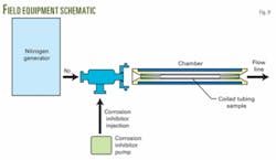
After the yard test, the final step was a field trial that included an additional component in the surface rig up. This component was a chamber in the treating line, containing a sample of the CT string placed after the N2 and corrosion inhibitor injection points. A drawing of that component is shown in Fig. 9.
The purpose of this chamber was to enable us to check the string condition at intervals, with the CT and BHA still in the hole, while the treatment was performed. This chamber allows CT operations personnel to inspect the sample of coiled tubing without pulling the BHA out of the hole. Although the coiled-tubing sample in the chamber was at surface temperature, corrosion was still observed when corrosion inhibitor was not used, or when improperly dosed.
Merluza platform test
We performed the first field trial in five wells from the Merluza platform. This coiled-tubing operation involved pumping pure nitrogen and commingled nitrogen and a blend of 5% acetic and 7% formic acid.
The results of this field trial showed results similar to those obtained in the laboratory and yard trials. We saw very little corrosion on the CT string in the chamber, with no plugging of the BHA. Also, very low corrosion rates were observed on the CT string after the five-well campaign was completed.
Learnings
Based on the laboratory tests, yard, and field trials, we found that corrosive environments involving nitrogen generator units can be controlled within an acceptable level by using appropriate corrosion inhibitors and procedures. Experiments also demonstrated that selecting the right inhibitor and concentration is fundamental to achieving positive results. Based on this study, we conclude that membrane gas remains an effective and economically feasible solution for CT operations off Brazil.
When liquid nitrogen is used, it requires an average of three tanks (2,000 gal each)/ well in a 24-hr period. No more than three tanks could be stored on the platform and, with no support ships near the location, a standby time of about 30 hr is was incurred to obtain additional liquid nitrogen supplies.
Even after a support ship arrived, another 15 hr was necessary to transfer liquid nitrogen to tanks on location. In total, at least 11.8 days was the average time required to finish one well and obtain enough nitrogen for the next.
When the membrane unit replaced the liquid nitrogen tanks, we saved a total of 6.8 days of standby and transfer time. Additionally, using nitrogen membrane units results in less equipment on location, saving additional space. It also required less time/job, and saved all costs related to nitrogen transportation, resulting in wells being brought back into production faster.
Acknowledgments
The authors thank Petrobras and BJ Services Co. for allowing us to publish this study.
References
- Coiled Tubing Technical Catalog, Quality Tubing Inc., March 1997, Houston, Tex.
- Alfonso, Luiz Otávio Amaral, Equipamentos Mecânicos: Análise de falhas e solução de problemas, published by Petrobras, Rio de Janeiro, 2002.
- Gentil, Vicente, Corrosão, 4ta Edição, published by LCT Editora, 2003.
Based on a presentation to the SPE/ICoTA Coiled Tubing and Well Intervention Conference, Apr. 1-2, 2008, in the Woodlands, Tex.
The authors
Luis H. Duque ([email protected]) is group leader of Latin America and West Africa for coiled-tubing operations with BJ Services Co., based in Rio de Janeiro. Since 1996, he has served as coiled-tubing operations manager in Brazil; trainer in BJ´s research center in Tomball, Tex.; and engineering and marketing manager in Venezuela and Trinidad. Duque has also worked as stimulation engineer for PDVSA in Lake Maracaibo, 1991-96. He holds a BS (1991) in mechanical engineering from UNET – National Experimental University of Táchira, Venezuela. Duque is a member of the Society of Petroleum Engineers.
Zacarias de Oliveira Guimarães Neto ([email protected]) is the coiled-tubing marketing and engineering coordinator in Brazil for BJ Services Co., based in Natal, Brazil. He has also served as coiled-tubing coordinator with Halliburton in Macaé from 1998-2004. Guimarães holds a BS (1998) in mechanical engineering from Federal University of Itajubá, Minas Gerais, Brazil. He is a member of SPE.
Sandra L. Berry ([email protected]) is a research scientist for BJ Services Co. at the BJ Services’ technology center in Tomball, Tex. She has also served as the completion brine reclamation and QC group leader at OSCA, 1984-2001. Berry holds a BS (1981) from Southeastern Louisiana University. She is a member of SPE.
Manoel Antonio Gonçalves de Gouveia ([email protected]) is a technical advisor for well services with Petrobras in Macaé, Brazil. He has been with Petrobras for 26 years in several positions in production operations and well services. Gouveia holds a BS (2008) in petroleum engineering from University Estácio de Sá in Macaé. He is a member of the SPE.
