GAS TURBINES—Conclusion: Supersonic ejector saves fuel gas, reduces CO2 emissions
Several tests conducted on various configurations of a two-stage supersonic ejector to capture low-pressure gas and discharge it for re-injection into a higher-pressure stream for use as fuel gas arrived at optimum design and operating parameters. The optimum design gave an expansion pressure ratio (motive:suction) on the order of 14.0 and compression pressure ratio (discharge:suction) of around 8.1.
The first part of two articles (OGJ, Jan. 14, 2008, p. 54) summarized this optimum configuration of the supersonic nozzles, particularly for the first-stage ejector. This second, concluding article presents the performance test results of the integrated system and describes a successful implementation of the supersonic ejector unit at one of TransCanada’s compressor stations in Alberta on a compressor-gas turbine unit rated at 24 Mw.
Integrated performance
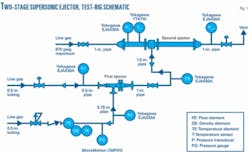
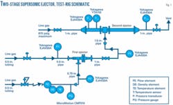
Fig. 1 shows the integrated test rig with the two-stage ejector and the corresponding pressures, temperatures, and mass flow rate measurements. Tests conducted on the second-stage ejector alone optimized the position of its supersonic nozzle with respect to the diffuser inlet. Best performance occurred with the position of the nozzle exit at 1.42 mm upstream from the inlet section of the supersonic diffuser.
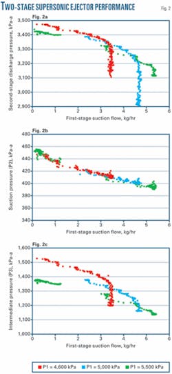
Varying P1 to the first-stage ejector (4,600 kilopascals-atmospheric, 5,000 kPa-a, and 5,500 kPa-a), while maintaining the motive-gas pressure (Pin) to the second-stage ejector at maximum line pressure of about 6,000 kPa-a tested the ejector’s two-stage configuration.
Fig. 2 shows the results of the integrated two-stage ejector system in terms of the discharge pressure from the second-stage ejector, suction flow at the first stage, and the intermediate pressure (P3) for different P1. Fig. 2a also shows the effects of varying (P1): The lower the P1 the higher the suction flow, but at the expense of overall discharge pressure (Pout).
This optimized configuration can deliver the required discharge pressure (Pout) of 3,300 kilopascals-gauge with a suction flow of 2-2.5 kg/hr and suction pressure (P2) of 340 kPag. These values match the requirements for this ejector to work with a dry-gas leakage and a typical fuel-gas line on a typical compressor station. Motive gas flow to the first stage is 0.016 kg/sec (based on 5,000 kPa-a pressure) and to the second stage 0.464 kg/sec (based on 6,000 kPa-a pressure).
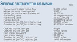
Recognizing that the motive gas to the second-stage ejector is drawn from the compressor discharge side (~6,000 kPag), allows assessment of the balance-of-plant with regard to net energy saved by capturing vent gas from the dry-gas seal. Compressor suction pressure of ~5,000 kPag and a pressure ratio of 1.2 yield excess power drawn by 0.464 kg/sec motive-gas flow of 9.3 kw.
Assuming thermal efficiency of the combined gas turbine-compressor of 30% results in 31kw extra fuel use due to motive-gas compression. Gas savings resulting from capturing the dry-gas seal vent gas of 9.0 kg/hr amounts to 130 kw (based on gas heating value of 39.3 mega J/cu m), leading to a total net energy saving in fuel gas of about 99 kw.
The supersonic ejector also reduces CO2 emissions by 1,600 tonnes/year (Table 1).
Implementation plan
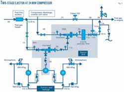
TransCanada plans to implement the newly developed gas-gas ejector system at its compressor stations system-wide based on results of real-time testing on a 24-Mw compressor at one of its stations in Alberta, skid-mounting the integrated two-stage ejector system with additional pressure gauges (shaded area, Fig. 3).
The chosen centrifugal compressor unit’s high utilization hours led to its selection, allowing evaluation of the performance of the ejector system across a wide range of operating conditions and fluctuating loads. Ease of the shutting down the unit without interrupting service to customers also guided the selection process.
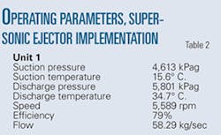
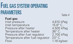
The seal-gas leak line currently going to atmospheric vent uses a flowmeter and a check valve. Table 2 gives the compressor’s operating parameters, Table 3 provides the primary gas seal parameters both at the drive end, and nondrive end, and Table 4 details the selected compressor’s fuel-gas system. These parameters guided the implementation design.
Fig. 3 shows the two primary dry-gas leakage lines from the two DE and NDE dry-gas seals connecting to form the suction to the first-stage ejector. Two check valves prevent any back flow into the seal area.
Adding backpressure regulators on the seal vents slightly modified the existing dry-seal monitoring system. Back pressure increased to 500 kPag from 160 kPag. The existing rupture discs rating remained static at about 700 kPag, with the shutdown set point set at 600 kPag. If the ejector cannot pull gas from the primary vent, these two regulator valves will vent the gas to atmosphere so as not to risk the dry-gas seal.
The rupture discs will continue to provide the same functions if pressure increases above 700 kPag. The increase in the back pressure on the primary seal to 500 kPag from 160 kPag will not damage the integrity of the dry gas seal.
First-stage motive gas came from a tie-in line from the outlet of the fuel-gas filter upstream of the Fisher 310 control valve. Pressure varies between 4,600 and 5,800 kPag. The compressor discharge line downstream of the unit valve supplied second-stage motive gas, typically at 6,000-6,600 kPag.
The supersonic nature of the two stages and the gas expansion through the respective nozzles results in extremely cold gas temperatures, corresponding to conditions inside the gas two-phase envelope. The exit velocity of the gas from the supersonic section, however, is extremely high, preventing thermodynamic equilibrium. Even if small condensation droplets formed, they would move at enormous velocity into the diffuser section of the respective stage and evaporate due to the diffuser’s compression.
A gas coalescer filter installed on the ejector skid at Location 5 filters the final discharge gas from the ejector before in enters the fuel-gas line. Buffer gas is used to flush the seal chamber of debris or dirty gas, and keeping the seal environment clean requires use of the gas coalescer filter. Some buffer gas will eventually leak into the primary seal gas system and eventually into the fuel gas through the ejector, further reinforcing the need for the coalescer filter (Fig. 3).
A higher back pressure on the primary dry-gas seal could result in gas migrating to the secondary dry seal, located near the magnetic bearing cavities. Failure of the purge air and migration of the gas into the magnetic bearing cavities, combined with an ignition source inside the bearing cavities, could result in an explosion. It is, however, highly unlikely that anything would create an ignition source inside the magnetic bearing cavities during start-up, shutdown, or the bearings being de-energized.
An outer seal labyrinth on the gas seal that has barrier air going to it, outboard of the secondary vent, makes it very difficult for gas to enter the bearing chamber. Any gas that gets across the secondary seal will be pushed out to the secondary vent by the barrier air, which should be vented to atmosphere.
An air purge to the bearing chambers, also vented to atmosphere, helps dispose of any additional gas that crosses the secondary seal. Positive pressure on the bearing housings should help keep process gas from entering. The barrier labyrinth should also help prevent combustible gas from migrating into the magnetic bearing chamber.
As long as the system is working properly, with barrier air flowing, there should be no process gas getting into the bearing chamber. The magnetic bearing design has no ignition source since the whole magnetic bearing assembly is sealed and should be contact-free (rotor and stator) with an air gap providing dampening and the magnetic field needed to achieve its function.
A differential pressure monitoring device, if working properly, will also trigger a unit shutdown on reversed pressure differential between the magnetic bearing cavities and the secondary dry seal; i.e., purge air or seal failure.
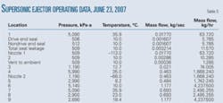
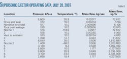
Table 5 shows data collected on June 23, 2007, after commissioning. Table 6 provides data taken on July 20, 2007, after 1 month of continuous operation.
