A unique coiled-tubing method can serve as a model for several offshore pipeline repairs the US Mines and Minerals Service has mandated occur by 2010. The method successfully deoiled a total of 4,190 ft of a buried pipeline length of 7,500 ft and isolated the balance between two plugs, in compliance with MMS requirements.
This article reviews the pipeline damage to which this CT method was first applied and discusses the various options considered to ensure the line’s safety and prevent future leakage and environmental damage. It then describes in detail the preparation for and successful performance of the CT deployment.
Background
The West Delta 109A platform stands in 250 ft of water at the mouth of the Mississippi River. Crude oil production runs 39,000 ft through an 8-in. pipeline to a 12-in. tie-in at WD 125. In July 2005, tropical storm Cindy separated the pressure-balance safety joint on the 8-in. crude riser. Surveys followed passage of the storm and in accordance with approved MMS procedures, several steps were taken to assess damage.
A lock out at the platform and blind flange installed at the base of the riser deoiled and isolated it. Divers found the separated end of the pipeline 300 ft to the southwest. Reconnecting the riser required a total of 300 bbl sea water pumped into the line behind a soluble ball and a soft foam pipeline pig, displacing oil from a 5,000-ft section of line. Before displacement of the line was completed, however, Hurricane Katrina entered the Gulf of Mexico, forcing suspension of operations.
Sidescan sonar and magnetometer equipment surveyed the pipeline after Katrina and a dive-support vessel with excavation equipment and divers mobilized to search for it. Both the survey results and physical inspection by divers showed the pipeline had undergone major additional movement during Katrina.
When pressure testing the pipeline revealed a leak, the dive support vessel was mobilized to its rough location after multiple days of digging and probing, however, the DSV could not locate the pipeline in the area where there was believed to be a leak. The DSV demobilized and further planning was initiated to come up with a procedure to locate the pipeline. A new technique located the leak in the pipeline using a mass spectrometer to detect the highest product concentration on the seafloor. The highest concentration would hopefully coincide with the location of the pipeline leak. A second mobilization occurred and a 200 × 200 ft hole was excavated to a depth of 26 ft.
The divers, however, failed to find the damaged pipeline, showing it was buried deeper than 236 ft.; the 26 ft. already exposed and 10 more surveyed by magnetometer.
Subsequent plans to deoil the pipeline divided it into four sections; two pipeline segments on each side of the damaged leaking pipe, one section from the riser to the damaged pipeline, and the final section between the main line tie-in and the other side of the damaged pipeline.
Deoiling plans
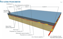
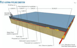
Fig. 1 shows the complexity of the problem faced on the remainder of the pipeline. The roughly 6,500-ft section from the cut towards the pipe line tie-in was partially filled with water as far as the foam pig, and the balance filled with oil to the point labeled Location B, before disappearing into the mud slide area for a total of 7,500 ft. Somewhere in this section lay a rupture or perhaps several, until the line became accessible again at Location A, with the balance of 20,000 ft to the tie-in unaffected and no additional leak or rupturing detected.
Three distinct sections therefore required attention, two of them were readily accessible to divers while the third, containing the rupture(s), was totally buried. Each section would require different treatment: The section from Location A to the tie-in could be pumped out; the section from the cut to Location B would lend itself to a pump and pig receiver approach using the pig already in place; but the buried segment presented problems in terms of deoiling while retaining the contents.
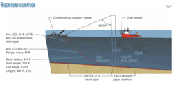
Chevron, in consultation with contractors, decided the buried section could most easily be accessed via CT working from a service barge by way of a custom-built riser attached to the line by divers. A 4-in. riser system designed to be made up to the buried line at Locations A and B separately and attached to the barge at 15° to vertical provided for attachment of the CT injector head. A final meeting held in July 2007 reviewed and refined the plans, with the operation scheduled for August 2007.
Operation
The first stage prepared the pipeline to allow access for CT operations. This involved plugging the line at Locations A and B, cutting into it, and installing block valves to isolate the buried section. A diving support vessel (DSV) provided the base for the following steps:
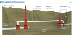
- Divers installed stopples (pipeline plugs inserted into the line through a hot tap and valve fixture) at Location B some 20 ft apart (Fig. 2) to provide space for the custom riser.
- A hose was then attached from a pump on the service barge at Location B to one of the stopple flushing ports and a return hose connected to the other leading to tanks on the vessel and allowing the line between the stopples to be flushed clean.
- Placing a pollution dome around the section between the stopples allowed the line to be cut in two places 4 ft from each stopple, the 12-ft section to be removed, and flanges and ball valves installed and closed.
- The stopples were then retracted, the hot tap valve closed and plugged, and the stopple housings removed from both fittings.
- The process was repeated at Location A.
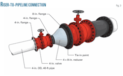
In the meantime the two 4-in. risers arrived on the DSV as 32 40-ft flanged sections and were assembled into three joint sections; the lower end of the riser being equipped with a 4-in. ball valve and a transition to an 8-in. flange for installation onto the cut end of the buried pipeline section (Fig. 3), the upper end with a 4-in. flange. Divers connected the separate sections of the riser to the cut end of the line at Location B after they’d been lowered to the seabed, with the final section being attached to a recovery wire and buoy on surface.
The DSV moved to Location A, while the coiled-tubing support vessel (CTSV) was mobilized to Location B and, with the recovery wire and vessel crane, lifted the end of the riser to the surface while the vessel maneuvered to maintain the required riser curvature and place the top of the riser at the vessel deck at 15° to vertical (Fig. 4).
Rigidly attaching the riser to the CTSV preceded pressure testing to 250 psi to verify its integrity. The first test failed and the entire riser had to be laid down, the CTSV moved, and the riser gaskets replaced by divers before a good test could be obtained. Reattaching the riser to the CTSV preceded cutting it to length, welding another flange in place, and again pressure testing the riser to 250 psi.
Testing followed makeup of the injector head, and the bottomhole assembly (BHA), consisting of the following components, was picked up and run first into the riser and then into the pipeline:
- Bull plug.
- Inflatable retrievable production packer with 2.875-in. OD.
- Pressure-activated relief assembly.
- Pressure-actuated disconnect.
- Coiled-tubing connector.
The BHA became hung up at a depth of 2,022 ft, equivalent to 1,371 ft inside the buried pipeline and, despite efforts to continue its progress, it would go no farther. Pressure applied to the CT to 500 psi and then to 1,250 psi set the packer and increased to 2,000 psi to shear open the pressure relief assembly. Set down and pickup weight applied to the packer verified its setting, a ⅝-in. ball was dropped and circulated to its seat, and 5,000 psi of pressure applied to the CT to shear the disconnect loose.
After raising of the CT a short distance, seawater circulated the riser and pipeline to the CTSV tanks until returns were clean, after which the CT was retrieved, the unit disengaged, the riser detached and lowered back to the seabed, and the 8-in. ball-valve closed.
The entire process led to substantial deoiling of the upstream end of the damaged section of line, with a permanent plug put in place to retain the balance of the pipeline contents.
A similar operation at Location A prepared the other end of the buried section for isolation and, following relocation of the CTSV, the same basic deoiling steps were repeated. In this case the BHA stopped at a depth of 3,459 ft equivalent to 2,819 ft inside the pipeline, where the packer was set, the relief valve sheared open to establish circulation, and the ⅝-in. ball dropped and pumped to seat to release from the packer.
Seawater then circulated the pipeline clean as before, taking returns into the CTSV tanks before the riser was lowered to the seabed.
The authors
Ignacio Quintero III ([email protected]) serves as project manager at Chevron Pipe Line Co. in Bellaire, Tex. He has also served as project engineer at Shell Oil Co. and senior facility engineer at Delphi Automotive. He holds a bachelors degree in mechanical engineering (1997) from the University of Texas at El Paso. He is also a licensed professional engineer in the state of Michigan.
Bob Murphy ([email protected]) is global product line manager, thru-tubing packers with Weatherford International Ltd, based in Houston. He has 29 years of experience running packers and bridge plugs in completion and remedial applications. Murphy has spent the last 10 years working exclusively with coiled tubing conveyed packers, including thru tubing inflatables. He is a member of the Society of Petroleum Engineers (SPE) and the Intervention & Coiled Tubing Association (ICoTA).
Joe Bob Maddox ([email protected]) is a thru-tubing specialist at Weatherford International in Broussard, La. He has also served as downhole tool specialist for Techline Oil Tools and Elder Oil Tools.
John M. Noddin ([email protected]) is president at Critical Path Consulting, Beaumont, Tex., and specializes in project management for the oil and gas industry. He has also served as senior project manager for both manufacturing and service companies. He holds a degree in mechanical engineering from Texas A&M University, College Station. He is a member of ASME and SME.
