After 30 years of refinements, mud-pulse systems transmit data more quickly and more accurately, through increasingly deep wellbores. Operators are pushing telemetry systems to transmit real-time data quickly, in lieu of using wired pipe or waiting for wireline data.
The economic success of many drilling operations depends on the availability of real-time information about the drilling process. Mud-pulse telemetry is currently the most common method of transmitting measurement-while-drilling (MWD) and logging-while-drilling (LWD) data. Advances in downhole sensing for drilling optimization and formation evaluation are placing heavy demands on equipment to provide faster data rates from greater depths.
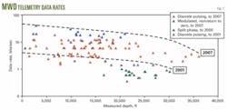
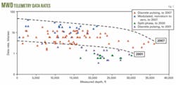
As a result, mud-pulse telemetry rates have improved to more than 20 bits/sec (bps) at depths shallower than 20,000 ft, and in excess of 3 bps from depths of more than 36,000 ft. In 1978, a typical data rate was 0.4 bps.
This article describes the evolution of mud-pulse telemetry and the technology advances that have resulted in today’s improvements in reliability and data rates. In particular, new self-oscillating shear valves give mud-pulse systems new flexibility and adaptability in highly variable drilling environments, used by Norsk Hydro ASA and Statoil AS.
Rationale—higher data rates
The effectiveness of MWD and LWD services depends on the scope of downhole measurements available to the operator, the data density (points/foot on a real-time log), and the data accuracy. Because the telemetry uplink from downhole to surface can convey only limited data, MWD and LWD services compete for the same resource. Therefore, the number of downhole measurements directly affects real-time data density.
Assuming the same rate of penetration (ROP), an increase in the number of real-time MWD and LWD services directly results in a reduced log density for every measurement. To maintain data density for increasingly complex MWD bottomhole assemblies, we can either boost the telemetry data rate or lower the ROP.
With expensive rig rates, particularly for offshore drilling, the economic impact of lowering ROP renders this choice unacceptable. Thus, increasing telemetry data rate is the only reasonable option to cope with the large amount of data generated downhole.
System evolution
Various telemetry systems have been and are under investigation: wired pipe,1 mud pulse,2 3 electromagnetic,4 and acoustic.5 Mud-pulse telemetry has proven to be reliable and cost-effective and is the most common MWD telemetry system.
The earliest telemetry patent was issued in 1929, but current mud-pulse telemetry systems date from work by J.J. Arps published in 1964.6
Teleco introduced the first commercial MWD mud-pulse tool in 1978. This tool transmitted directional information to surface at about 0.4 bps.
Data rates stabilized in the 1980s and 1990s at 0.4 to 3 bps. This rate was sufficient to transmit reliably MWD and LWD data at that time. In the 1990s, development of new LWD tools and introduction of rotary steerable drilling systems and real-time drilling dynamics tools placed considerable pressure on the ability of this transmission link to maintain data density. In response, engineers developed a reliable MWD telemetry system that was delivering unprecedented raw data rates by the close of 2007 (Fig. 1).
System design
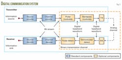
As with any digital communication system, a mud-pulse telemetry system has distinct components (Fig. 2). The receiver side of the system mirrors the transmission side. An information sourcethe downhole sensorprovides the data for transmission to the surface information sinkpersonnel controlling the drilling operation.
To reduce the amount of transmitted data and to cope with limited bandwidth, an optional source encoder performs source compression. A corresponding source decoder decompresses at the receiver. Source compression algorithms either discard information (“lossy” compression) or retain all the information (“lossless” compression).
To protect the bit stream from errors introduced by the transmission channel (flowing mud-filled pipe bore), an optional channel encoder adds error protection. The channel decoder in the receiver uses this information for error detection and correction. Since the additional information reduces the available net bandwidth, there is a trade-off between telemetry reliability and net data-rate reduction for each measurement.
After channel encoding, a digital modulator transforms the data bits into analog waveforms that propagate readily in the mud column (modulation). The typical waveform is a pulse and the process is known as pulse modulation.
On the receiver side, the pulse detector interprets pulses and transfers data back to the bit. The pulse waveform can either be directly emitted by the pulser (positive and negative pulsers used by several MWD companies) or it can be shifted towards a higher frequency before transmission (“passband modulation”). The mud siren style of an MWD pulser uses the latter type of shifting, for example.
On surface, pressure sensors measure the transmitted waveforms. In the case of passband-modulated data, the receiver signal is demodulated before passing it to the pulse detector to reconstruct the binary data.
To increase the pulse detection quality and thus the reliability of the telemetry link signal, the signal needs to be reconstructed before demodulation and pulse detection to remedy the destructive effects of the analog mud channel on the signal shape. Signal reconstruction is one of the most critical steps in reliably boosting the transmission data rate and was rigorously investigated during the development of this MWD telemetry system.
Attenuation, reflection
In mud-pulse telemetry, the transmission channel is the mud-filled bore of the drill string. Pressure waves travel up the mud column, are attenuated, and partially reflected. The energy of the pressure wave received on surface is just a fraction of the energy emitted by the mud pulser downhole. The attenuation increases with depth, frequency of the signal and compressibility of the mud. For example, oil-based mud is highly compressible relative to water-based mud and higher transmission frequencies are, therefore, more attenuated.
In 1972, Desbrandes et al. published a comparison of theoretical and measured pulse attenuations.7 Their results have been referenced extensively in numerous publications on mud-pulse telemetry. This work, however, oversimplifies the effects of the mud-pulse channel because it neglects the fact that the signal reflects at pipe diameter changes, hoses, T-pieces, pump pulsation dampeners, etc.
The reflections add constructively for some frequencies and destructively for others, which means certain frequencies are amplified while others are attenuated. This “frequency selectivity” effect causes signal transmission to fail on certain frequencies while transmitted successfully on other frequencies.
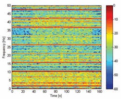
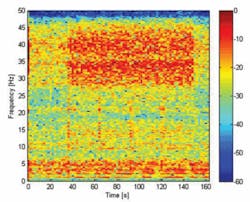
In addition to frequency selective attenuation, the signal suffers from interfering noise signals (mud pressure fluctuations induced by mud pumps and the drilling process, thermal noise of the electronics, etc.). The dominant noise component is pump noise generated by the pistons of the pumps. Fig. 3 shows a spectrogram of the modulated signal; the pump noise is clearly visible as brown horizontal lines. The telemetry signal is recognizable as the yellow shaded area from 40-140 sec in the range of 28-45 hz.
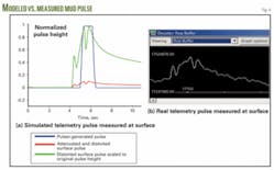
The success of data transmission depends not only on the attenuation of the individual frequencies but also on their distortion, and on the level of noise present in the measured signal. Real-time modeling of the signal traveling through the mud channel, as shown in Fig. 4, allows us to achieve higher data rates. After correcting for attenuation and distortion, and removing additive noise, we get to the spectrogram shown in Fig. 5.
Mud pulser design
Since mud-pulse attenuation depends on depth and mud type, it is advantageous for optimum MWD signal transmission to have a pulser capable of transmitting data in different frequency bands. For shallow water-based mud systems, passband modulation provides a bandwidth unmatched by pulse-based systems. For deeper wells or oil-based muds, it is necessary to be able to switch to discrete pulsing for reliable transmission, since these lower frequency waveforms suffer less attenuation.
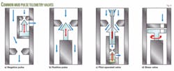
Various types of valves generate pulse pressure in the flowing mud (Fig. 6). These valves either bypass flow to the annulus (negative pressure pulsers) or restrict flow (positive pressure pulsers). Most mud pulsers used in the oil industry are positive pulsing valves. Various valve options include cone valves (act in or against flow direction), rotary valves (open and close perpendicular to the fluid flow), or fluidic valves (change the flow pattern).
In the early 1960s, Mobil Oil published a patent for an LWD system using a rotary valve to transmit data to the surface (the “screamer”).8 This transmitter used a continuous wave up to 24 hz and transmitted data by phase-shifting the signal to encode the data. The system had a source signal amplitude of 100 psi and was successfully tested at rates up to 3 bps downhole.
Schlumberger adapted this idea of using a rotary valve in the development of its “Mud Siren.”
In 1978, the first commercial MWD system marketed by Teleco contained a hydraulically driven poppet valve, powered by a powerful multistage turbine and oil pump.10 In contrast to the small signal amplitudes of rotary valves, the Teleco pulser created strong, discrete signals easily detected on surface, even from deep wells or in situations with high pump noise. This pulser achieved data rates up to 2 bps in commercial applications.
Dresser developed another commonly used mud-pulser system, especially suited to the low electrical power consumption required of battery-powered MWD systems.11 The initial system monitored the revolutions of a downhole turbine and Spinnler, at Teleco, used an electrically driven pilot valve to drive a main valve for mud-pulse telemetry.12
Design optimizations continued after the 1992 merger of Eastman Christensen and Teleco. These companies were incorporated into Baker Hughes INTEQ in 1993.
These pulser systems provided sufficient telemetry data rate to deliver the required data density to surface when there was relatively low availability of real-time formation evaluation services and relatively low ROP.
With the introduction of rotary closed coop drilling systems, penetration rates increased dramatically. The available telemetry data rates led to ROP restrictions or low data density. In addition, an expansion of LWD and MWD services put severe demands on the available MWD transmission data rate.
In 1977, the US Energy and Development Administration published a report giving a broad overview of the available MWD and telemetry systems.13 By the early 2000s, not much had changed in terms of data rate or mud-pulse systems, although the systems had been optimized for reliability.
Oscillating pulser
The existing systems delivered either strong, discrete pulses or low- amplitude continuous waves. Engineers needed a new pulser combining both options to ensure independence from the highly variable drilling environment: deep or shallow wells, oil- or water-based mud systems, complex or simple bottomhole assemblies, high or low drilling rates or, indeed, any combination of these conditions.
An oscillating shear valve pulser driven by a precise motor controller is able to fulfill these needs (Fig. 7). Designed as a self-oscillating system, such a pulser is capable of delivering a telemetry bandwidth of 40 hz or more with low power consumption.
Norsk Hydro ASA used shear valve pulser technology in deep water off Norway in 2006, at depths to 22,000 ft. Petrobras also used shear valver pulser systems off Brazil in 2007.
The oscillating movement has various advantages over the legacy rotary valves. The system can self-oscillate with low power consumption at high speeds. During each oscillation cycle, the valve runs through a zero speed state, in which phase or frequency can be changed instantaneously for efficient telemetry modulation, providing high telemetry data rates.
In contrast to rotary valves, oscillating valves can be adapted to flow rate and mud weight changes even when the tool is downhole. Only the oscillation amplitude must change to keep the pulse pressure constant, and the oscillation angle can be easily adjusted by a downlink when flow rate or mud weight changes are required.
Another advantage of an oscillating valve is that it can transmit discrete pulses to surface, in addition to the passband-modulated signal. In cases where high frequencies are attenuated, the oscillating valve can be set to discrete pulsing. With high-end motor controllers, even the pulse pattern can be changed at each oscillation cycle.
Either higher harmonics of the pressure signal can be reduced by shaping the motor speed profile, or the shape of the pressure pulse can be fully controlled to create sinusoidal, trapezoidal, rectangular, or any other shaped signals to enable maximum signal pressure at the source and optimum downhole signal quality for high decoding quality at surface. These features are not possible with legacy rotary valves.
Oscillating systems are also less prone to jamming from foreign bodies within their moving components. These pulsers open and close in opposite directions. A jammed foreign body is released as soon as the valve opens again. Only the signal amplitude decreases while the foreign body passes through the valve. In a rotational valve, the foreign body gets stuck, and backward rotation is required to free the body.
The basic idea behind this adaptable mud pulser is that each drilling application is different. Because the rig environment cannot be easily changed, the pulser must be adapted to the application, even when already run downhole. The adaptability of the pulser to its environment ensures optimum signal quality.
Mud-pulse receiver
The receiving antennas in a mud-pulse telemetry system are one or more pressure sensors mounted in the standpipe. For good decoding of the received signals, the telemetry signal energy has to be significantly above the noise energy.
To boost mud-pulse data rates, there are generally two options; either (a) increase the telemetry signal energy so that the received energy on surface is sufficiently higher than the energy of interfering noise, or (b) cancel out noise by signal reconstruction algorithms before handing the signal over to the demodulator and pulse detector.
Since the mud pumps are a major source of noise and are located on surface, pump noise cannot be attenuated. The energy of the telemetry signal would have to be increased by several orders of magnitude, which renders approach (a) difficult. Signal reconstruction by surface-processing algorithms, Option (b), is more viable.
Surface signal reconstruction is the key to reliable high data rate mud-pulse telemetry. It has to remedy two types of distortion: noise and frequency selectivity. Noise usually is assumed to be additive and can be subtracted as soon as we have an idea what it looks like, which is the difficult part.
We can either model noise or estimate it from measurements. A measurement-based approach is much more robust since it inherently includes the effects of every detail of the particular rig setup. The level of complexity required to model the equivalent would be too great.
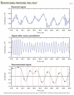
For noise cancellation, we apply linear prediction and space diversity processing similar to the description in literature.14 Fig. 8 shows receiver signal processing of data transmitted through water-based mud in a Troll field well drilled by Norsk Hydro off Norway. These data came from about 17,400 ft MD, at 10 bps on a 30-hz carrier frequency. The middle drawing depicts the signal, after canceling out the effects of the transmission channel (distortion and interfering noise). It clearly shows the recovered, sinusoidal, 30-hz carrier signal. The bottom drawing depicts the corresponding demodulated signal. The vertical red lines mark the beginning of a bit and the black cross on top of the signal in the middle of a bit indicates the logical decision of the pulse detection logic. If the cross is above the zero line, a ‘1’ was transmitted and ‘0’ otherwise.
After noise cancellation, we can estimate the frequency-selective attenuation and equalize it based on transmitted reference signals (i.e., known signals). The optimum parameter set for signal transmission (discrete pulsing or passband modulation, data rate, and if applicable, signal frequency) is determined by the resulting signal after noise cancellation and equalization.
Only this signal shows the final ratio of signal energy to noise energy, which needs to be maximized for optimum telemetry data rate. Therefore, it is inevitable to have a downhole transmitter capable of full parameter adjustment via downlink. This closed-loop approach to MWD telemetry systems has enabled the high data rates demonstrated by the new system.
Achievements
While it is certainly possible to describe the achievement of MWD telemetry in terms of signal reconstruction under adverse transmission conditions, it is also instructive to list the raw data rate milestones through late 2007. All data was generated with shear valve pulsers, except for Sakhalin:
- 40 bps from 3,000 ft, Baker Hughes experimental test area, Beggs, Okla.
- 30 bps from 9,865 ft, onshore North America.
- 27 bps from 11,394 ft (40 bps while off-bottom), off Brazil.
- 20 bps from 20,991 ft, off Norway.
- 9 bps from 23,215 ft, Trollfield.
- 4.0 bps from 29,123 ft, Sakhalin.
- 3.5 bps from 34,570 ft, Sakhalin.
- 3.0 bps from 36,075 ft, Sakhalin.
We can expect raw data rates to push both higher and deeper in the near future.
References
- Wolter, H., et al., “The First Offshore Use of an Ultra High Speed Drillstring Telemetry Network Involving a Full LWD Logging Suite and Rotary Steerable Drilling System,” paper SPE 110939, 2007 Annual Technical Conference & Exhibition (ATCE), Anaheim, Nov. 11-14, 2007.
- Spinnler, Ralph F., and Stone, Frederick A., “Mud pulse logging while drilling telemetry system: design, development and demonstration,” 1978 IADC Drilling Technology Conference, Houston, Mar. 7-9, 1978.
- Klotz, Christian, et al., “A New Mud Pulse Telemetry System for Enhanced MWD/LWD Applications,” paper SPE 112683; 2008 IADC/SPE Drilling Conference, Orlando, Mar. 4-6, 2008.
- Smith, H.C., “Toroidal coupled Measurements While Drilling,” paper SPE 11362; 1983 IADC/SPE Drilling Conference, New Orleans, Feb. 20-23, 1983.
- Gao, L., et al., “Acoustic Telemetry Delivers More Real-time Downhole Data in Underbalanced Drilling Operations,” paper SPE 98948; 2006 IADC/SPE Drilling Conference, Miami Beach, Feb. 21-23, 2006.
- Arps, J.J., and Arps, J.L., “The Subsurface Telemetry ProblemA Practical Solution,” paper SPE 710; Journal of Petroleum Technology, May 1964, pp. 487-93.
- Desbrandes, R., et al., “MWD Transmission data rates can be optimized,” Petroleum Engineer International, June 1987.
- Godbey, John K., US Patent 3309656, “Logging-while-drilling system,” published Mar. 14, 1967 (Mobil-Oil).
- Patton, B.J., et al., “Development and Successful Testing of a Continuous Wave Logging While Drilling Tool,” paper SPE 6157; 51st Annual Meeting of the Society of Petroleum Engineers, New Orleans, Oct. 3-6, 1976.
- Stone, Frederick A., US Patent 4266606, “Hydraulic circuit for borehole telemetry apparatus,” published May 12, 1981 (Teleco Oilfield Services Inc.).
- Jeter, John D., US Patent 3065416, “Well apparatus,” published Nov. 20, 1962 (Dresser Industries).
- Spinnler, Ralph F., US Patent 3958217, “Pilot operated mud-pulse valve,” published May 18, 1976 (Teleco Inc.).
- McDonald, W.J. “Borehole measurements while drillingsystems and activities,” prepared for the US Energy Research and Development Administration, division of geothermal energy, June 1977.
- Proakis, John G., Digital Communications, 4th edition, New York: McGraw-Hill, 2001.
The authors
Ingolf Wassermann ([email protected]) is a project engineer for Baker Hughes INTEQ, based in Celle, Germany, with 3 years’ experience in the oil drilling industry. He currently works as technical lead for surface software development of mud-pulse telemetry systems. Wasserman holds a Diploma (2004) in communications engineering from the Gottfried Wilhelm Leibniz University Hannover, Germany.
Detlef Hahn ([email protected]) is engineering manager for Baker Hughes INTEQ, based in Celle. He has over 15 years’ experience in the oil drilling business, has held various positions in marketing and engineering, and is currently working as project lead for development of downhole tools for mud-pulse telemetry. Hahn holds a Diploma (1991) in mechanical engineering from the Gottfried Wilhelm Leibniz University Hannover.
Hanno Reckmann ([email protected]) is engineering manager for Baker Hughes INTEQ, based in Houston. He has more than 5 years’ experience in the oil drilling industry, including 3 years developing mud-pulse telemetry. Reckmann is manager of drilling dynamics, analyzing and simulating drillstring and BHA dynamics. Reckmann holds a PhD (2002) in mechanical engineering from the Gottfried Wilhelm Leibniz University Hannover.
Dang Hai Nguyen ([email protected]) is project engineer for Baker Hughes INTEQ, based in Celle. He has worked on mud-pulse telemetry for 3 years and is currently a communication engineer developing surface systems for telemetry. Nguyen holds an MS (2006) in communications engineering from the Gottfried Wilhelm Leibniz University Hannover.
John Macpherson ([email protected]) is program manager for telemetry and dynamics at Baker Hughes INTEQ, based in Houston. He has over 30 years’ experience in the oil industry, working in operations, marketing, and engineering. Macpherson currently leads a research and development group based in Celle and in Houston, focusing on MWD telemetry systems and drilling dynamics. He holds a BS (honors, 1974) in geology from University of Glasgow, Scotland, and is a member of SPE and IEEE.
