INTEGRITY MANAGEMENT—Conclusion: Procedure, FEA apply to NGL fitness-for-service assessment
A simple economic procedure applied to NGL pipelines can help operators determinebased on the type, shape, and position of any abnormalities detected during periodic magnetic-flux leakage pigging whether to shut the pipeline for repair or continue operations.
The first part of two articles (OGJ, June 9, 2008, p. 80) described the three steps of this procedure:
- Identification. A magnetic-flux leakage intelligent pig report and ultrasonic Scan B testing located the defect.
- Quantification. Ultrasonic thickness measurement and Scan B results use gammagraphic inspection to determine the defect’s size and location on the pipe wall.
- Assessment. A simple finite-element analysis model simulates the real defect and then corroborates results against API Recommended Practice 579 Fitness for Service, January 2000.
This concluding article applies the procedure and FEA directly to a fitness-for-service assessment.
FEA
The procedure next performed a simple linear elastic FEA on the pipeline defect zone based on different load scenarios (OGJ, June 9, 2008, p. 81, Table 1). The FEA consists of various steps:
- Model creation.
- Definition of material properties.
- Model FE discretization.
- Definition of input boundary conditions.
- Graphical results display.
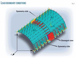
A pipeline quarter model used the symmetry of the section and elastic shell element because it is suitable for analyzing characteristics of thin material. A rectangular area with dimensions quantified during non destructive inspection modeled the damaged zone.
The next step introduced material properties, FE discretization, load, and input boundary conditions. Material properties used in linear elastic analysis included: the Young Modulus, 2.1 × 10⁶ kg/sq cm for carbon steel; Poisson coefficient, 0.29; specified minimum yield strength, 448 MPa; and specified ultimate tensile strength, 531 MPa. Testing applied different values of internal pressure to the pipeline model (Fig. 1).
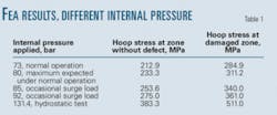
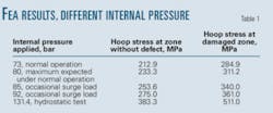
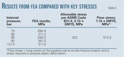
The hoop stress on the defect zone increased to 2,849 kg/sq cm from 2,129 kg/sq cm when the pipeline was under normal operating conditions. Linear elastic analysis yielded similar graphical results for different internal pressures. Table 1 summarizes FEA results.
Internal pressure creates pipeline wall stresses in both longitudinal and circumferential (hoop stress, Sx and Sy) directions. Circumferential stress generally measures twice the longitudinal stress. Hoop stress formulas indicated in ASME Code B31.4, Para. 404.1.2 (Barlow’s equation modified for pipelines) guide pipeline design and wall thickness.1
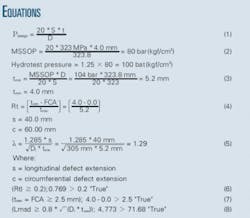
Equation 1 calculates the internal design pressure known as maximum steady-state operating pressure of the NGL pipeline according to B31.4 ASME Code. Hydrostatic pressure tests performed at 131.4 MPa (1.25 × MSSOP) assumed a pipeline wall free of defects, consistent with code requirements. This variance required revision of all cases in Table 1, comparing the hoop stress from FEA on the damaged zone with allowable stress according to B31.4 and flow stress in an effort to determine if the pipeline could still be safely operated at various pressure levels.
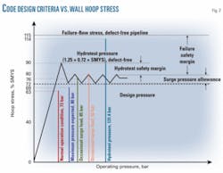
Graphic comparison of the hoop stress on the damaged pipeline segment and design-code criteria helped understanding of the real state of the pipeline wall at various working pressures (Fig. 2).
Design-code criteria established elastic limit design allowable stress as 72% SYMS, hydrotest pressure as 90% SYMS, and flow stress as 115% SMYS.
Hoop stress on the damage zone below the code stress limit (284.9 MPa < 323 MPa; Sy < 72% SYMS) allows the NGL pipeline to keep operating under normal conditions (73 bar). If normal pressure increased to 80 bar, hoop stress on the damaged zone would remain within allowable stress limits (311.2 MPa < 323 MPa).
Surge pressure could develop if main valve LVS 5 was closed during normal pipeline operation. Hoop stress in both cases (85 and 92 bar) would exceed the allowable stress, but code permits this kind of occasional effect whenever created hoop stress remains below 0.8 × SMYS.
Assuming the defect occurred during manufacturing, the damaged pipeline zone underwent hydrotest pressure reaching 114% SYMSalmost failure stressbut no plastic deformation or cracks appeared.
Equation 1 provided the basis for calculating a new MSSOP and hydrotest pressure, establishing the new operation condition for the pipeline damaged zone (Equation 2).
A fitness-for-service assessment consists of the quantitative analysis of the adequacy of a component to perform its function in the presence of a defect. The first three types of defects (pipe mill, transportation, and construction defects) should be detected during construction, preoperational testing, and commissioning, before the system is turned over to the operator. Missing these defects during construction and later discovering them, however, requires a fitness-for-service analysis.
A fitness-for-service assessment based on 2000 API 57, Section 5, “Assessment of Local Metal Loss,” corroborated the results obtained through the FEA. Level 1 assessment evaluated a component subject to internal pressure and determined the acceptability of any component with a flaw.
The procedure has six steps:
- Step 1. Determine the critical thickness profile. UT Scan B inspection found the following parameters:
Di = 305 mm, ID.
D = 323.8 mm, OD.
FCA = 0.0 mm, future corrosion allowance.
Lmsd = 4,773 mm, distance from the edge of the defect to the nearest structural discontinuity (e.g., weld).
MSSOP = 104 bar, maximum steady-state operation pressure.
RSFa = 0.9, remaining strength factor allowable. - Step 2. Calculate minimum required thickness, tmin, based on current design pressure according to code B31.4 (Equation 3).
- Step 3. Determine minimum measured thickness, tmm, remaining thickness ratio, Rt, flaw dimensions, s and c, and shell parameter, λ (Equations 4 and 5).
- Step 4. Check limiting flaw size criteria for a Level 1 assessment (Equations 6-8).
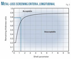
- Step 5. Evaluate the flaw’s longitudinal extent. If the point the intersection of these values defines lies on or above the line describing acceptable values of Rt and λ in Fig. 3, the longitudinal extent of the flaw is acceptable.
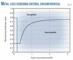
Fig. 3 shows λ = 1.29 and Rt = 0.769, placing the longitudinal flaw on the acceptable side of the line. - Step 6. For a cylindrical shell, evaluate the circumferential extent of the flaw with Fig. 4, using the calculated values c/Di and Rt. If the point the intersection of these values defines lies on or above the line describing their acceptable levels, the circumferential extent of the flaw is acceptable.
Reference
- American Society of Mechanical Engineers, B31.4, “Pipeline transportation systems for liquid and hydrocarbons and other liquids,” 1998 Ed., New York, April 1999.
