GAS TURBINES—1: Supersonic ejector captures, reinjects leaked vent gases
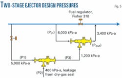
A two-stage supersonic ejector can capture low-pressure gas such as that being vented from a typical first stage dry-gas seal, and discharge it for re-injection into a higher-pressure stream at 3,400 kPa (atmospheric) for fuel-gas utilization.
The ejector device seeks to capture gas leakage from a dry-gas seal at low pressure and reinject it into the fuel-gas line to the gas generator (without the use of compressors or rotating elements), allowing the use of gas that would otherwise be vented to atmosphere. This device eliminates costs associated with gas loss and reduces greenhouse gas emitted by the dry-gas seal to the atmosphere.
Leakage gas pressure of 70-340 kPa (gauge) presents one of the primary problems mitigating against reaching these goals, with a minimum pressure required downstream of fuel-gas regulators of 2,400-3,400 kPag.
The device consists of a two-stage supersonic ejector. The first stage is highly supersonic (nozzle exit Mach 2.54), while the second stage is moderately supersonic (nozzle exit Mach number ≈1.72).
Several tests conducted on various configurations of the two stages on natural gas arrived at the optimum design and operating parameters. The optimum design gave an expansion-pressure ratio (motive:suction) on the order of 14.0 and compression pressure ratio (discharge:suction) of around 8.1. These ratios would meet the requirement of minimum suction and discharge pressure mentioned above.
This first part of two articles summarizes the optimum configuration arrived at after several iterations of different geometries of the supersonic nozzles, particularly for the first-stage ejector. The second, concluding article presents the performance-test results of the integrated system and describes a successful implementation of the supersonic ejector unit at one of TransCanada PipeLines’ compressor stations in Alberta on a compressor-gas turbine unit rated at 24 Mw.
Background
Ejectors have the advantage of no moving parts. No seals, no shafts, no packing, and therefore no maintenance also stand out as distinct advantages over mechanical compressors or vacuum pumps, which often require elaborate maintenance programs. Their rugged construction and simplicity of design enable reliable, maintenance-free use.
Although considered inefficient in general, ejector use in a wide range of industrial applicationssuch as power plants for the creation of vacuum,1 power and thrust augmentation,2 3 refrigeration and heat pump systems,4-6 gas-vapor recovery from oil storage tanks, transport of solids,7 oil production,8 aero-engine cooling,9 bubble-bed tower reactors, and bioreactors10has become common.
Current work focuses on extending application of ejectors to capture gas leakage from dry gas seals and reinject it into a higher pressure fuel-gas stream going to the combustor of the gas turbine driving the gas compressor.
Such use would not only save the leaking gas and use it as part of fuel gas, but also eliminate hydrocarbon emissions. It would also eliminate the need for additional energy to drive the ejector, drawing its motive gas from the fuel-gas line prior to throttling.
Reinjection of the leakage gas into the gas generator fuel-gas line presents a better option than directing it to a lower pressure utility fuel-gas line (e.g., in boilers) because boilers typically operate intermittently (on-off), instead of firing continuously while compressor units are running.
Leakage gas pressures from the first stage dry-gas seals in the range of 70-340 kPag, with minimum pressure required downstream of the fuel-gas regulator (typically Fisher 310A type) in the range of 2,400-3,300 kPag, depending on the gas-turbine model, pose the primary problems facing reinjection. Commercial ejectors typically work either in the subsonic or slightly supersonic regions, limiting suction pressure with respect to motive gas pressure.
Fletcher, for example, documents a discharge pressure calculation curve showing motive gas at 7,000 kPa-a and suction-gas pressure of 350 kPa-a yield a maximum discharge pressure achievable at about 1,400 kpa-a.11 The same curve shows a motive pressure of 7,000 kPa-a, and a discharge pressure of 2,800 kPa-a, create a minimum suction pressure of 900 kPa-a.
The same study also showed that, for a discharge pressure of 4,100 kPa-a and a suction pressure of 1,300 kPa-a, the required motive-gas pressure would be 10,300 kPa-a, demonstrating the difficulty of meeting the low suction pressure while discharging to a much higher pressure.
Overcoming these difficulties prompted development and testing of a two-stage supersonic ejector12 using a highly supersonic first stage (nozzle exit Mach number = 2.54) and a moderately supersonic second stage (nozzle exit Mach number = 1.72).
Several tests of various configurations of the two stages on natural gas yielded optimum design parameters; an expansion pressure ratio (motive-suction) on the order of 14.0 and compression pressure ratio (discharge-suction) of around 8.1.
This article presents the optimum configuration arrived at after several iterations of different supersonic expansion nozzles, particularly for the first stage, and presents the measured performance results of the integrated system that would meet the requirements of capturing the low-pressure, low flow dry gas seal leakage and reinject it into the fuel-gas stream.
Dry-gas seal vent-gas pressure matching the pressure of the suction gas to the first-stage ejector should not adversely affect operation of the dry-gas seal, as will be discussed later in this article.
Leakage rates
A typical dry-gas seal is a noncontact end-face seal with a sealing mechanism consisting of two rings. The first ring, with grooves etched in the seal face and rotating with the shaft, is the mating ring. The second ring has a smooth face and is restrained from movement except along the axis of the shaft. These seals often co-exist as pairs, providing a two-stage sealing effect.
Successful operation requires supplying a steady flow of clean seal gas to the gaps between the rings. The seal supply gas source must maintain a higher pressure than the process gas being sealed for flow to occur. Overhung compressors require just one dry seal, allowing seal supply gas to be drawn from the compressor discharge, filtered, and supplied in a steady flow to the seal capsule.
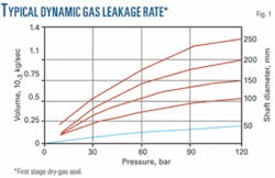
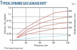
Most seal supply gas reenters the process cavity, with a small volume (leakage) passing through the seal faces and venting to atmosphere. The amount of gas leakage depends on the process pressure and rotating shaft diameter.
Fig. 1 gives an example matrix of the order of magnitude of gas leakage from a typical first stage dry-gas seal.
Current supersonic ejector development focuses on providing a means of capturing gas leakage and reinjecting it into the fuel-gas line, saving fuel and reducing greenhouse-gas emissions.
Supersonic problems
Supersonic ejectors’ primary problem is compressing the combined (motive + suction) gas in the supersonic diffuser part of the ejector. The diffuser throat has to be larger than the nozzle throat to account for stagnation pressure losses both through jet entrainment-mixing and at the inlet of the converging supersonic section of the diffuser. An insufficiently large diffuser throat would cause a standing shock inside the nozzle and destroy the desired expansion in static pressure.
A variable throat diffuser can swallow standing shock13 14 but complicated design too badly to be used in this application. A diffuser throat made slightly larger than needed instead kept standing shock either slightly downstream of the diffuser throat or at the throat itself.
Computational fluid dynamics analysis carried out to discern the flow field, accompanied by extensive testing of various configurations, helped reach the optimum design of a fixed-geometry diffuser that could work with different nozzles of different throat area. Previous literature presented both the results of these efforts14 and the methodology used to arrive at the optimum configuration.
The optimized nozzle-diffuser arrangement showed the nozzle clear from a standing shock wave and achieving good suction. The diffuser section’s shock wave region (the region where Mach number drops sharply from supersonic to subsonic) lies at the throat of the diffuser or slightly downstream of it. The filing of patent applications for the above ejector configuration has occurred in both Canada and the US.15 16
First stage
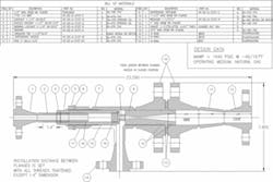
Satisfying the relatively low suction pressure to match the dry-gas seal leakage pressure (~400 kPa-a) in the context of this discussion requires an ejector with a highly supersonic exit flow, bringing with it the problem associated with compressing the same supersonic flow after entraining the dry-gas seal leakage gas in a supersonic diffuser. Fig. 2 shows the flexible prototype designed and fabricated in an attempt to reduce the likelihood of a shock wave at the throat of the supersonic diffuser.
This design not only allows various geometry supersonic nozzles to be tested with a fixed geometry diffuser, but also fine adjustments of the position of the nozzle exit in relation to the diffuser inlet (either positively, i.e., inserted into the diffuser inlet section, or negatively, i.e., retrieved back with a gap in between nozzle exit and diffuser inlet).
The supersonic diffuser has an inlet diameter of 4 mm, a throat diameter of 3.5 mm, a length of 8 mm, and an exit diameter of 18 mm. Inlet 1⁄2-angle of the inlet section is 4.7°, with the exit section 5°.
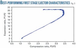
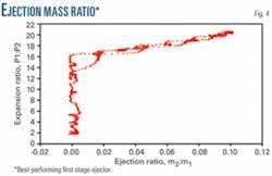
Fabrication of several supersonic converging-diverging nozzles with different throat diameters and exit-throat area ratio, yielded a peak performance configuration of 1.6 mm (throat) × 2.8 mm (exit) nozzle placed 20.5 mm inside the supersonic diffuser. Figs. 3 and 4 show test results of the first-stage ejector with this nozzle size in terms of expansion ratio (P1:P2), compression ratio (P3:P2), and suction to motive gas flow ratio. Motive-gas pressure (P1 = 5,000 kPa-a) produced an expansion ratio of 20 and compression ratio of 3.5.
null
Second stage
The second-stage ejector’s size and design allowed it to use full line gas pressure as motive gas without throttling and discharge at a pressure (Pout) up to 3,400 kPa-a (Fig. 5). The suction flow to the second stage is the exit flow from the first-stage ejector.
Numerical simulation using a one-dimensional gas dynamics model through the second-stage supersonic nozzle arrived at the nozzle area’s ratio, from which a nozzle exit to throat area’s ratio of 1.382 was selected as the nozzle’s exit pressure matching the outlet pressure from the first-stage ejector.
CFD simulations then optimized supersonic diffuser dimensions (throat, inlet, and outlet diameters, as well as angles) and position of the nozzle with respect to diffuser inlet.
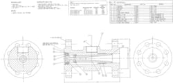
Fig. 6 shows the optimum design of the second stage.
Acknowledgment
The authors thank TransCanada for using the supersonic ejector on a compressor station in Alberta, Dwayne Krause for valuable assistance in designing the overall system, and both Vladimir Bakalchuk of John Crane and Sorin Necula of Dresser-Rand for valuable consultation during the initial phase of the implementation plan. This work is part of a research program sponsored by TransCanada PipeLines Ltd.
References
- Power, R.B., “Predicting Unstable-Mode Performance of a Steam Jet Ejector,” Fluid Power Systems Technology, Collected Papers, ASME, 1994.
- Freeman, B.Z., and Lior, N., “A Novel High-Temperature Ejector-Topping Power Cycle,” Journal of Engineering for Gas Turbines and Power, Vol. 116, pp. 1-7, January 1994.
- Minardi, J.E., “Compressible Flow Ejector Analysis with Application to Energy Conversion and Thrust Augmentation,” AIAA 20th Aerospace Sciences Meeting, Orlando, Jan. 11-14, 1982.
- Huang, B.J., and Chang, J.M., “Empirical Correlation for Ejector Design,” International Journal of Refrigeration, Vol. 22, pp. 379-388, 1999.
- Huang, B.J., Chang, J.M., Wang, J.M., and Petrenko, V.A., “A 1-D Analysis of Ejector Performance,” International Journal of Refrigeration, Vol. 22, pp. 354-364, 1999.
- Chen, S.L., Yen, J.Y., and Huang, M.C., “An Experimental investigation of ejector performance based upon different refrigerants,” ASHRAE Transactions, Vol. 104, No. 2, pp. 153-160, June 1998.
- Sun, Da-Wen, and Eames, I.W., “Recent Developments in the Design Theories and Applications of Ejectorsa Review,” Journal of the Institute of Energy, Vol. 68, No. 475, pp. 65-79, June 1995.
- Villa, M., De Ghetto, G., Paone, F., Giacchetta, G., and Bevilacqua, M., “Ejectors for Boosting Low-Pressure Oil Wells,” SPE Production and Facilities, Vol. 14, No. 4, pp. 229-234, November 1999.
- Hu, H., Kobayashi, T., Saga, T., Taniguchi, N., Liu, H., and Wu, S., “Research on the Rectangular Lobed Exhaust Ejector-Mixer Systems,” Transactions of the Japan Society for Aeronautical and Space Sciences, Vol. 41, No, 134, pp. 187-194, 1999.
- Zahradnik, J., Fialova, M., Linek, V., Sinkule, J., Reznickova, J., and Kastanek, F., “Dispersion Efficiency of Ejector-type Gas Distributors in Different Operating Modes,” Chemical Engineering Science, Vol. 52, No. 24, pp. 4499-4510, December 1997.
- Fletcher, G.R., “Gas Jet Compressors,” Petroleum Refiner, pp. 107-111, February 1954.
- Botros, K.K., Geerligs, J., Imran, H., and Thompson, W., “Development of a Supersonic Ejector for Capturing Very Low Pressure Vent Gases and Re-injection into a High Pressure Stream,” 6th International Pipeline Conference, Calgary, Alta., Sept. 25-29, 2006.
- Shapiro, A.H., “The Dynamics and Thermodynamics of Compressible Fluid FlowVol. 1,” E. Krieger Publishing Co., Malabar, Fla., pp. 972-973, 1983.
- Zucrow, M.J. and Hoffman, J.P., Gas Dynamics, Vol. I, John Wiley & Sons Inc., 1976.
- Botros, K.K., Geerligs, J., and Imran, H., “Tandem Supersonic Ejector,” Canadian Patent Application, September 2006.
- Botros, K.K., Geerligs, J., and Imran, H., “Tandem Supersonic Ejector,” US Patent Application, May 2007.
Based on presentation at the 17th Symposium on Industrial Application of Gas Turbines, Banff, Alta., Oct. 15-18, 2007.
The authors
Kamal K. Botros ([email protected]) is a researcher for NOVA Research & Technology Center in Calgary. Over the past 28 years he has worked on various fluid flow-equipment dynamic problems related to industrial facilities and petrochemical manufacturing plants. Recent activities include advances in stochastic methods and dynamic programming for multi-objective optimizations of large design space problems, and measurements of decompression wave speed following ruptures of high pressure rich-gas pipelines. He holds a PhD in mechanical engineering from the University of Calgary.
John Geerligs ([email protected]) has spent the past 10 years conducting experimental research projects at NOVA Research & Technology Center’s Gas Dynamics Test Facility near Didsbury, Alta. His expertise lies in applying the latest improvements in electronic instrumentation devices to measurement and analysis of high-pressure-gas dynamic pressure and flow phenomena. He holds a diploma in electronics technology from the Northern Alberta Institute of Technology in Edmonton.
Hasan Imran (hasan_imran@transcanada) is working as a senior environmental advisor at TransCanada Corp. He is responsible for climate change and air issues related to existing natural gas pipeline and power plants along with new acquisitions. Over the past 15 years he has worked in the petrochemical industry, with particular experience in oil refining (atmospheric and vacuum distillation), gas processing, and fertilizer and cement manufacturing. He has a master’s degree in chemical and petroleum engineering with specialization in engineering for the environment from University of Calgary. He earned a bachelor’s in chemical engineering in Pakistan. He is a registered professional engineer in Alberta.
