Single-set CT straddle packers successful in Alaska
At Prudhoe Bay, Alas., nonrig tubing repairs have become a viable alternative to rig workovers (RWOs). This type of repair provides economic remediation for wells with production tubing by “A” annulus communication.
Wireline-set retrievable straddles can eliminate tubing communication at a significant cost savings. They are particularly attractive in areas where RWO cost is significant, such as offshore, remote, or arctic locations. The advantage of tubing straddle repair over a conventional RWO is that there is no need to pull tubing, resulting in the well being returned to service faster.
Typical straddle deployment costs are less than 5% of the costs for tubing replacement with an RWO. Single-set or “one-trip” straddles were used historically at Prudhoe Bay. However, starting in 1994, a less expensive, retrievable, two-run straddle design was adopted.
A 2006 study of 263 permanent and retrievable tubing straddles set in 181 wells at Prudhoe Bay showed that single-set straddles were far more successful and lasted longer than two-set straddles.1
This article describes the recent development, history, and success rate of a retrievable, single-set tubing straddle for 4½-in. and 3½-in. tubing. It details the modifications required to convert an hydraulic set straddle pack-off to a one trip wireline set system. Twenty-nine of these straddles have been set at Prudhoe Bay to date, improving the straddle program success rate to 80% from about 50%.
New solution
Prudhoe Bay is a mature, enhanced oil recovery/waterflood oil field. Mechanical problems with the original completions have traditionally been repaired with a rig to replace the tubing. The majority of these wells were completed with 4½-in. and 5½-in., L-80 carbon steel production tubing.
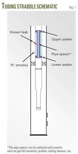
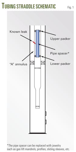
BP has made significant cost savings by deploying the alternative remediation technique discussed in this article, and the workovers may result in the recovery of additional reserves. Tubing straddles are designed to eliminate production tubing by “A” annulus communication (Fig. 1).
They consist of two sealing elements connected by a pipe spacer to straddle and isolate the source of tubing by “A” annulus communication. They can be installed in producers or injectors to isolate leaks in damaged gas lift mandrels (GLMs), jewelry, tubing collars, and eroded or corroded tubulars.
Historical straddle analysis
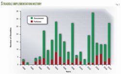
The history of tubing straddles set at Prudhoe Bay from 1986 to 2005 is detailed in SPE 107069.1 The paper also gives a complete description of prestraddle diagnostics and includes lessons learned from the 20-year straddle program. The number of straddles and the success rate have varied considerably over the years and are updated in Fig. 2 with data through 2007. A successful straddle is defined as one that has passed a successful poststraddle pressure test.
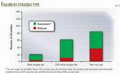
One unexpected outcome of the study is the clear difference in the straddle success rate between the single-set straddles compared to the two-run straddles (Fig. 3). Two-run straddles were introduced in mid-1994 and were appealing because of their lower cost. Although single-set straddles continued to be run, their use declined until 2002 when almost all of the straddles were the two-run style.
The study showed that the “old-style” single-set straddles had had a success rate of 82%, compared with the two-run straddles which were successful only 55% of the time. Initially, it was thought that this difference might be due to more aggressive candidate identification in wells which had corrosion damage. However, only 28% of straddles are set to isolate tubing holes due to corrosion.1 The team felt that the extra seal in a two-set straddle was resulting in the increased failure rate.
This assessment has proven to be accurate, as 29 of the new single set straddles have been deployed and have a 79% success rate. This is a dramatic improvement in the success rate of 57% in 2004 and 46% in 2005. This significant increase in success rate is solely due to the development of the single-set straddle.
Single-set straddles
After evaluating the 1986-2005 historical straddle study results, BP asked Baker Oil Tools to design a one-trip, wireline-set, retrievable straddle packer system that would be modular in design. A modular system was requested to allow for variable straddle spacer lengths depending on each well’s requirements. Additionally, the new system would allow jewelry (typically consisting of gas lift mandrels or sliding sleeves) to replace the spacer pipe.
The straddle length was initially required to be 35 ft between sealing elements. This is typically the longest conventional straddle that can be deployed due to lubricator length and fishing considerations.
Requirements of the single-set straddles included:
- One trip wireline deployed.
- Easily retrievable via slick line or coiled tubing.
- Modular design.
- 3½-in. ST-L connections.
- 3,500 psi pressure rating @ 230 °F.
- Set using Baker No. 10, E-4 wireline setting tool.
- Initial design to be 35 ft between sealing elements.
Single-set straddle operation
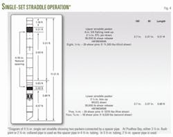
In single-run straddle deployment, both packers are set simultaneously, with a spacer pipe connecting them, to straddle the source of communication (Fig. 4).
The spacer pipe has a secondary tube through it to the bottom of the assembly. The tube transmits the setting force to the bottom packing element and extrudes it to the tubing wall to achieve a seal.
A standard hydraulic system was converted to a mechanical set system that is capable of deploying in one trip and packing off both sealing elements during setting. This requires that the two packers be mechanically connected to one another in such a way that as mechanical axial force is applied to the assembly, both sealing elements and lower slip are energized to allow packing off. To accomplish this, the system was converted from using internal hydraulic pistons (to apply compression to the assembly to induce slip setting and pack-off) to a mechanically induced axial compression load between the two pack-offs.
The packers were modified to make the originally fixed bottom ends “free floating.” This allows axial forces to travel through, and between, the bottom of the packers and into the slips/pack-off. Only one set of slips can be used in the system and the optimum placement for them is in the lower packer. This is necessary because of the axial movement of the assembly during setting. If the upper slips are in place, they will contact the tubing wall and prevent any additional axial movement down. This prevents the upper assembly and spacer tubes from moving down and energizing the lower pack-off. The lower assembly is unable to move up because it is retained by the lower slip.
The setting sequence design involves the following:
- Shear up and set lower slip. This stops any additional axial movement up.
- Shear down and pack-off lower element.
- Shear down and pack-off upper element.
- Shear setting tool.
The use of only one slip section to maintain the assembly in position downhole has been determined to be satisfactory for the straddle application. The assembly is pressure balanced above and below, thus no axial movement can be induced due to pressure variations. Pack-off energy is maintained in the upper and lower elements via body lock rings as originally designed.
The rubber elements consist of a 70 durometer center element and 90 durometer end elements. The Baker Model No.10, E-4 setting tool is used to generate the required mechanical axial forces to squeeze the two packers into a set position. Setting rods run through the bore of the assembly and attach to a wireline adapter kit. The adapter kit is retained within a machined profile within the bottom sub of the lower packer. The straddles are rated to 3,500 psi. However, they have been tested in the shop, as well as on location, to as high as 4,000 psi.
Field operations
Baker set its first successful single-set straddle in January 2006 in 4½-in. tubing. Two months later, it successfully deployed a 3½-in. straddle. The operations were similar to previous straddle setting procedures. After performing prestraddle diagnostics, technicians rig up wireline on the well.1 They arm the setting tools and make up the straddle. The tool string consists of:
- Electric-line head (the weak point and fishing neck in a small housing).
- Electronic release (disconnect).
- Casing collar locator.
- Baker-10 firing head.
On location, the operator test fires through the tool string to ensure continuity. The unit is then powered down and made up to the straddle that is horizontal on the ground. The assembly is pushed into the lubricator and a cap is screwed onto the lubricator bottom. The lubricator is picked up and stabbed onto the wellhead. The lubricator is pressure tested, the well is opened up, and the toolstring is run in at a maximum speed of 100 fpm.
Third-party cranes are required for longer straddles. Straddles are available in 5 ft increments up to 35 ft, but straddle length should be kept to a minimum length to ease handling requirements.
Results to date
The single set straddle program has been highly successful for both producing and injecting wells. To date, 29 straddles have been deployed in 26 wells. Four of these were set in 3.5-in. tubing and 25 were set in 4½-in. tubing. As shown in Fig. 1, overall success rate of the straddle program has increased to 79% from 52% over the last 4 years.
Nine single-set straddles were run in 2006 with two failures and a 78% success rate. Twenty were run in 2007 with an 80% success rate. Of the four failures in 2007, two are undiagnosed and “A” annulus fluid levels and other evidence suggest that there is likely a second leak and the straddle is holding.
To date, there have been six wells that have not been returned to service after running a single-set straddle. Again, this may be straddle failure, or it may be due to a second hole.
Immediate failures
Of the six failures, four of them were set at the target depth, but a subsequent pressure test of the “A” annulus failed, as discussed below:
Well 1. This 4½-in. straddle was set with no apparent problems after Baker had already successfully deployed five straddles successfully. The subsequent pressure test failed and a leak detection log identified a leak at the top of the straddle. The straddle was retrieved easily, and an intermediate length straddle was run, but still failed to solve the well’s tubing by “A” annulus communication. The well is currently has a procedure planned to rerun a single-set straddle with a modified target depth.
Well 2: Undiagnosed failure. This straddle was set over a damaged gas lift mandrel. The subsequent pressure test failed at a much smaller leak rate than prior to setting the straddle. A leak detection log is planned. It is suspected there is a second leak as a tubing caliper survey indicated the tubing had 46% wall loss above the straddle.
Well 3: Failure possibly temperature related. Reset was successful. This 4½-in. single-set straddle was set over a damaged gas lift mandrel at 4,258 ft. Instead of a spacer pipe between packers, it had a 23⁄8-in.special clearance gas lift mandrel to allow gas lifting through the straddled damaged mandrel. The poststraddle pressure test failed and a subsequent leak detection log indicated a leak at the straddle. After latching and jarring for 5½-in. hr with 0.125-in. slick line, and 1 hr 10 min with braided line, the straddle was successfully retrieved.
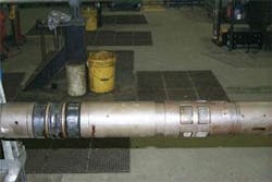
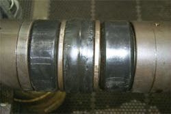
Inspection of the elements indicated that the center element (70 durometer) had been compressed. It was a little harder to discern that the two end elements (90 durometer) had been compressed (Figs. 5 and 6). However, the force the middle element was subject to was also transmitted to the outer elements. Both upper and lower packers should have seen a minimum of 11,000 lb of compressional force. A thorough inspection of the straddle confirmed the o-rings, shear ring, slips, and elements were in place and in good condition.
null
The temperature at the setting location was 35° F. and it is possible that although the end elements were subject to the same compressional force as the middle element, they weren’t elastic enough to extrude due to cold temperatures. Prior to the second straddle attempt, 590 bbl of 180° F. seawater and 225 bbl of 190º F. diesel were pumped to warm the wellbore to assist the elastomers to pack-off. Baker set the straddle successfully and it is still in service.
One mechanical change that was recommended, but not implemented was made to have a higher shear value for greater pack-off force. This would provide greater compressional force from the initial shear. A softer element could also be considered.
Although it is conjectured that temperature played a part in the failure of this straddle, a 4½-in. straddle was successfully set in the same well at 3,300 ft and would have been subject to similar cold temperatures. This second straddle is still in service after 1.4 years.
Well 4: Undiagnosed failure. This well had a 4½-in. straddle set to isolate a tubing hole. A poststraddle pressure test failed, and a diagnostic leak detection log is planned. Fluid levels indicate a second leak above the straddle.
Stuck straddles
Of the 29 single-set straddles that Baker has run, two of them (7%) were stuck above the target depth prior to setting. This was significant because the 1986-2005 study of 263 straddles indicated that only six straddles (2%) had become stuck due to tight spots which were not noted in the prestraddle slickline drift.
Well 5. Prior to setting this 4½-in. straddle from 12,295-12,310 ft, the well was drifted with a knuckle joint, 4½-in. gauge ring and 3.70-in. OD by 20 ft-long aluminum drift. The operational log noted some trouble at 10,625 ft and 11,256 ft. The area was worked with a 3.8-in. gauge ring, and a final drift run made three passes from 11,200-12,356 ft with the 20-ft drift.
An attempt was made to set a 35 ft long (element to element), 3.70-in. OD straddle. The overall tool string was 52 ft long. The straddle became stuck at 10,983 ft at a gas lift mandrel above the target setting depth. There was a 51º deviation at this gas lift mandrel, but no significant doglegs in the vicinity. After the straddle became stuck, the operator pulled off at the weak point. The straddle was fished and the well was redrifted with no problems noted.
A shorter straddle (21 ft, element to element, 37 ft tool string overall length) was then deployed. Although the tool string lost weight at 10,977 ft and continued to fall slowly, the straddle was set on depth. The shorter straddle was successfully deployed and pressure tested and is still in service. It was likely the problem with the first attempt was a downhole geometry issue.
Well 6. This 25-ft long, 3½-in. straddle with a 2.74-in. OD became stuck at a subsurface safety valve (SSSV) nipple with an internal diameter of 2.75-in. and length of 3.22-in. The well had a history of tight tolerances at the SSSV nipple. Four months before the failed setting attempt, slick line was unable to pass the SSSV nipple with a 2.73-in. centralizer. Immediately prior to the straddle setting attempt, slick line drifted with a 2.74-in. dummy straddle with no problems. Later, the OD of the dummy straddle drift was questioned.
During the straddle setting operation, the 25-ft straddle sat down in the SSSV nipple. The wireline operator pulled up the slack and pulled out of the head prematurely. Surface inspection indicated the weak point was worn, causing two of the four wires to pull out, instead of break.
After fishing the tool string, slick line redrifted with a 32-ft long, 2.74-in. barbell assembly with another vendor’s 2.74-in. straddle drift on bottom. The tool string was unable to pass the SSSV nipple. A swage turned down to 2.739-in. was able to work through the SSSV nipple with difficulty.
Baker was unable to turn down the 3½-in. straddle from 2.74-in. OD to 2.72-in. but did suggest a multiple run straddle system that could be turned down. A decision was made to use the other vendor’s modified two-run straddle turned down to 2.72-in. The lower packer was run on wireline and the upper packer and pipe spacer were run on slick line. The subsequent pressure test of the “A” annulus failed at 1 bbl/min. A leak detection log identified a second tubing leak in the joint below the straddle. The straddle was pulled, and a procedure to run a longer straddle is pending.
This example indicated that Baker’s one trip 3½-in. straddle (or the other vendor’s standard two-run straddle) is not ideal for wells with a 2.75-in. minimum restriction.
Until a few years ago, Prudhoe Bay had been operated by two different operating companies. The 2.75-in. SSSV nipples were more common in western operating area well completions and larger 2.81-in. nipples were used in the eastern operating area.
Importance of a prestraddle drift run. The example above illustrates why it is important for slick line to run a dummy drift tha accurately mimics the actual straddle to ensure tight spots are not encountered. The wellbore should be free of debris for about 200 ft below the setting depth. If the drift or a tubing caliper survey indicates tubing deposits, the straddle area should be brushed, scraped, or acidized so a better straddle seal can be obtained. The dummy straddle should also be the approximate length and the assembly should be run in the hole at the same speed the straddle will be run (typically 50-100 fpm). If the run is made at faster speeds, the slick-line tool string may sit down when going through tight spots, closing the spangs. This can allow the straddle dummy to “fall through” tight spots unnoticed. Wireline will not have this same capability, and the straddle may get stuck.
Well 7
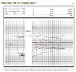
Only one well with a single-set straddle has exhibited tubing by “A” annulus communication since the straddle tested successfully. This straddle was in service a total of 1.4 years before failing. An ultrasonic leak-detection log verified that there was a leak in the upper packer or a tubing leak immediately above the straddle. Becuase a subsequent caliper indicated that the tubing was in poor condition above the straddle, the straddle may still have integrity and the leak may be the result of a second tubing hole.
It’s notable that the poststraddle leak detection log not only indicated the leak at or near the straddle, it also showed the original leak behind the straddle (Fig. 7). This commercially available log is able to detect leaks as small as 0.0025 gpm and has been used successfully in more than 65 wells on the North Slope.2
Fishing
There have been no problems fishing the single set straddles. On the two operations where straddles were stuck, wireline pulled out of the weak point and slick line subsequently fished the straddle. In retrospect, it may have been better to set the straddle where it was stuck and retrieve the setting tools, rather than pulling out at the weak point. Depending on wellbore configuration, setting the straddle may result in a much shorter, easier, one run fishing operation.
Observations
The high success rate of the single set straddle has increased confidence in straddle operations at Prudhoe Bay, with the following observations:
- The single set tubing straddle developed to set in 3½-in. and 4½-in. tubing at Prudhoe Bay had an 80% success rate. This is a significant increase over the about 50% success rate it has had in the last few years.
- Although there have been six failures, there is no single cause for failure. Continued analysis will improve candidate selection and prestraddle diagnostics.
- Only one straddle has failed since successfully set, with a life of 1.4 years. The study of 263 straddles set between 1985 and 2005 indicates a conservative life of 3.5 years. It is likely that average life for single-set straddles will be at least that long.
- A prestraddle drift that mimics actual straddle length and OD is very important to ensure a successful set, particularly for wells with tight tolerances.
- The development of single set straddles for 5½-in. and 7-in. tubing will improve the straddle program.
Acknowledgments
The authors thank the management of BP Exploration and BP’s Prudhoe Bay partners for permission to publish this work.
References
- Julian, Jennifer Y., Cismoski, Doug A., and Sack, Janet K., “Rigless Tubing Repair Using Permanent and Retrievable Straddles at Prudhoe Bay, AlaskaContinued Analysis and Current Applications,” paper SPE-107069, 2007 Production Operations Symposium, Oklahoma City, Apr. 4-5, 2006.
- Julian, J.Y., Johns, Joel E., Sack, J.K., and Robertson, Daniel B., “Detecting Ultra-small Leaks with Ultrasonic Leak Detection-Case Histories from the North Slope, Alaska,” paper SPE-108906, 2007 International Oil Conference and Exhibition in Mexico, Veracruz, June 27-30, 2007.
The authors
Jennifer Julian ([email protected]) is a senior well work intervention engineer at BP Exploration (Alaska) Inc., based in Anchorage. Previously she worked for Arco as a well site supervisor, production and injection engineer, and a log analyst. Julian holds a BS in petroleum engineering from the New Mexico Institute of Mining and Technology. She is a member of SPE and ICoTA.
R. Steven Rossberg ([email protected]) is Alaska wells manager at BP Exploration (Alaska), Anchorage. He is a member of SPE.
Carl W. Diller ([email protected]) is an operations manager at Baker Oil Tools thru-tubing division in Prudhoe Bay. He started with Baker Oil Tools in 1981 and has been involved in thru-tubing intervention (inflatable, production packers, liners, whipstocks, and CTD) since 1989. Diller holds a BS (1981) in marketing from the University of Northern Colorado.
Bob Harris ([email protected]) is a technical representative for Baker Oil Tools thru-tubing division in Anchorage. He has been involved in thru-tubing intervention (production packers, liners, whipstocks, and CTD) since 1989. Harris holds several CTD-related patents and has coauthored remedial and CTD related papers. He is a member of SPE.
Janet K. Sack ([email protected]) is a well intervention engineer for BP Exploration, Alaska. She specializes in well work intervention including slick line, wireline, and coiled tubing. Sack holds a BS in civil engineering from Gonzaga University. She is an SPE member.
Jake Flora ([email protected]) is a wellsite leader for BP Alaska Wells group. Previously, he has worked as a drilling engineer for Conoco-Phillips Alaska and as a tools & testing engineer for Halliburton Energy Services. Flora holds a BS (2002) in petroleum engineering from the University of Alaska Fairbanks.
