To produce the heavy oil from the JUB-6 well in the Jubarte field off Brazil, Petrobras decided to install the highest horsepower electric submersible pump (ESP) yet installed subsea. The system has a 1,200-hp motor and a pump capable of producing more than 22,000 b/d.
The well is part of Petrobras’ Phase 1 plan for the field that includes four wells producing about 60,000 b/d to the P-34 floating production, storage, and offloading (FPSO) vessel.
Two wells are on gas lift, one has an ESP installation on the seabed, and the fourth, discussed in this article, has a downhole ESP.
New technologies
As new deepwater discoveries enter the production phase, operators require new technologies to economically bring this production to market.
Many traditional subsea production systems for water depths less than 1,000 ft and with moderate stepouts are not applicable for fields in deeper water and with longer stepouts. Also, heavier oil becomes a consideration. Consequently, service companies and operators are seeking cost-effective ways for producing these reserves during the life of the fields.
Operators have traditionally preferred gas lift in subsea applications with relatively short stepouts in subsea areas off Brazil. But with high flow of heavy and viscous oil in a long stepout, gas lift becomes inefficient and ESPs provide the best artificial lift option.
The ESP in JUB-6 started operating in April 2007, 17 months after its November 2005 installation.
Reliability is a main concern with ESPs and, therefore, the system has to be properly selected for the particular application.
This first article of a two-part series describes the selected ESP system for JUB-6. The conclusion will provide details on system testing and qualification.
Downhole ESP
Jubarte field is in the north part of the Campos basin, about 80 km off Espirito Santo state.
The field, discovered in January 2001, had an extended well test for evaluating drilling, completion, artificial lift technology, and for verifying reserves.
The extended well test proved the economics of the field and Petrobras started Phase 1 development that includes four wells producing to the P-34 FPSO.
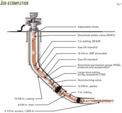
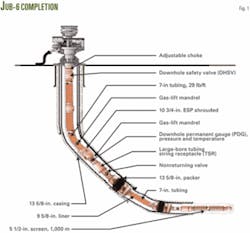
JUB-6 produces through 7-in. tubing, 26 lb/ft, ID 6.276 in (Fig. 1). The string is carbon steel except for the downhole safety valve (9% Cr) and the pup joint, crossover, and adjustable union above the safety value (13% Cr).
The well has a long horizontal, about 1,000 m, that creates a high productivity index and is openhole gravel packed for sand control.
The tubing string has gas lift mandrels for backup artificial lift if the ESP fails.
Water depth is about 1,400 m at Jubarte.
The well has 135⁄8-in. casing to about 2,480 m. The kick-off point is at about 2,175 m from the surface.
The ESP, installed at 0° from vertical, is encapsulated in a 10¾-in. flush joint capsule. The well has 95⁄8-in. liner from 2,480 m to 3,130 m. At this point, the well is already in the reservoir.
The 8½-in hole in the reservoir was drilled horizontally to about 1,000 m. The completion has a 7-in. gravel pack.
Above the gravel-pack packer, the well has a nonreturning valve (NRV). This valve prevents brine being injected into the reservoir during well-intervention work. The NRV is closed, isolating the reservoir, if the fluid weight above the NRV is greater than the reservoir pressure. The closed valve allows fluid to circulate through an orifice above the NRV with minimal or no loss of fluid to the reservoir. The orifice at the bottom of the string is in a gas lift mandrel.
The NRV is incorporated in the bottom string and is not pulled during intervention.
A tubing-string receptacle installed at about 2,385 m completes the lower string that has a gravel-pack assembly.
The pressure and temperature gauge sensor (PDG), manufactured by ProductionQuest, is set as close as possible to the reservoir for accurate reservoir readings. A T-wire cable (11 x 11 mm) runs from the wellhead to the sensor. This line has an epoxy encapsulation for improving the line’s resistance if something is hit downhole.
The encapsulated ESP is in a 10¾-in. flush-joint capsule at about 2,100 m from the surface. The T-wire cable to the PDG passes outside the capsule up to the mandrel. The installation required specially manufactured stamp clamp protectors for holding and preventing damage to the T-wire cable (feeding the PDG) through the capsule.
A gas-lift mandrel with a 3⁄8-in. orifice, just above the ESP capsule, provides lift gas in the event of ESP failure.
An adjustable union orients the cable to the hole of the wellhead hanger. Also, the excess cable slack is removed after connection of the subsea penetrator. This tool is capable of orienting 360° with a maximum misalignment of 30° and has a maximum stroke of 24 in.
Scale formation
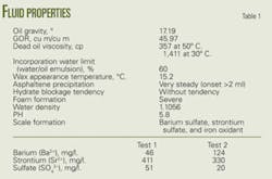
The Jubarte field produces a 17 °API gravity crude with about a 258 scf/bbl GOR (Table 1).
When the ESP that operated for 1 year in the extended well test was dismantled, inspectors found scale in the pump stages. The scale contained 86% barium sulfate, 12% strontium sulfate, and 2% iron oxidant. Also, two water analyses at two different points confirmed the quantity of solids present in the water (Table 1).
Scale formation is a function of pressure and temperature changes. The consequences of forming scale in and around the ESP are:
- If scale forms around the motor, the scale acts like a layer inhibiting heat transfer from the motor to the well fluid, causing the motor to run hotter.
- Scale incrustation on the impellers degrades pump performance and increases the risk of locking.
The design must take into account scale precipitation to prevent pump damage. The system included two different solutions:
- To further prevent scale deposition, the impellers and diffusers of the ESP have an Armor I coating. Armor I is a fluoropolymer coating that makes the nucleation and growth of scaling difficult and also aims to improve the physical properties of the pump stage material by reducing surface roughness and providing better pump performance. The fluoropolymer coating also protects pump parts against aggressive chemical agents and ambient factors.
- To reduce the potential precipitation, the system will also include continuous injection of an antiscale chemical product through the umbilical and chemical injection manifold. The injection point is at the pump intake.
Chemical injection can prevent scale formation but this well also produces a foamy oil with emulsion problems. Because the completion has only one injection line, the well required the development of a new chemical product that simultaneously acts as a demulsifier, antifoamer, and scale inhibitor.
The chemistry must be compatible with the metallic and nonmetallic components of the string, umbilical, and ESP system. Testing is still continuing for checking its compatibility.
The metallic compatibility test is based on the calculated weight loss for each coupon, and is expressed in mils/year (mpy) corrosion rate.
The test involves subjecting coupons of different materials to the chemical attached under simulated wellbore pressures and temperatures. The metals tested are materials from the housing, shafts, stages, and spring of the mechanical seals.
The nonmetallic compatibility test verifies that the elastomers are compatible with the well fluids (liquid and gas). They prevent contamination and recirculation of the fluid through critical points in the ESP equipment. Well fluids can attack the elastomer and affect its mechanical properties. The resistance of an elastomer to certain conditions is measured by these parameters:
- Volume change refers to the volume that the elastomer changes after contact with the well fluid at certain temperatures. The more volume changes, the worse the compatibility with the fluid.
- Tensile, elongation, hardness, and physical dimension changes in elastomers determine the capacity of the elastomer to work with the well fluid.
One product tested passed the metallic but not the nonmetallic compatibility test. The metallic test was successful with a maximum corrosion rate of 4.7 mpy. The nonmetallic test, at a concentration of 50,000 ppm (the injection rate in the well was calculated at 200 ppm) did not succeed.
Physical barriers, or bags, are in the seal section made of elastomers. During the test, the elastomer of the bag had high swell and low physical property retention (tensile strength, elongation, and hardness). Its size increased about 140%, and it also lost tensile strength, which means that the chemical attacked the elastomer.
This would reduce the run time of the ESP. The test involved a higher concentration of chemical from the proposed injection concentration because there are areas downhole in which the chemical could accumulate.
The product tested is soluble in oil, and the test was performed in water. It was suspected that the results will differ just by changing the base from water to a mixture between oil and water. The test was repeated with 5,000 ppm in a mixture of water and oil, and the results were good.
The elastomer did not lose any tensile strength in a water-oil base. The conclusion was that the product is compatible with the elastomers in this application.
ESP design
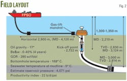
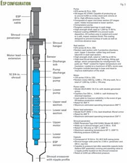
Fig. 2 provides general information on the ESP equipment.
Petrobras had requested a design for a 3,500-cu m/day production rate with other design specifications:
- Motor not to exceed 1,200 hp.
- Maximum 200-amp motor because of subsea penetrator limitations.
- ESP housed in a 103⁄4-in. capsule.
- Tubing string and ESP of carbon steel.
- Chemical injection to prevent scale formation, break emulsion, and foaming.
- Operate within the designed ESP operating range.
- Maximum 4,500-v motor. The selected motor was 4,160 v that can go up to 64.9 hz.
- A 62-hz maximum recommended operating frequency, as recommended by pump manufacturer.
- A 35-hz minimum starting frequency for no more than 30 min and a 40-hz minimum operating frequency. The compression pump has stages fixed to the shaft that have all downthrust forces that are transferred to the bearings in the seal section. The rpm is one parameter that forms the lubricating film between thrust runner and bearing. Lower speed leads to thinner lubricating film.
- ESP set in vertical position above the kickoff point.
- A discharge pressure below the maximum subsea flowline rating and an ESP burst-pressure housing below the subsea flowline rating.
- Variable-speed drive with filtered pulse width modulation power in the operation mode. It is not allowed to run the ESP without filtering, which could result in degradation of the motor and cable insulation due to poor quality of the wave signal.
- Carbon steel housing material.
- Addresses scale formation.
Design selected
Fig. 3 shows the main features of the selected pump and installation.
High-end technology motor construction improves motor reliability compared with standard construction. The extreme performance motor with Vanguard technology is a precision design manufactured to the highest industry standards.
The design features extreme high-load thrust bearings as well as an advanced hardened rotor-bearing system. The thrust bearings are a self-aligning design to compensate for any misalignment, and the rotor-bearing technology improves lubricity and vibration characteristics.
The high-strength shaft design incorporates proprietary materials to enhance run life in high-horsepower applications. High-temperature electrical connections provide a strong mechanical connection.
Like all Centrilift motors, the design features epoxy-encapsulated motor windings for enhanced stability and improved heat transfer.
The ESP sensor provides downhole communications with a discharge sub for discharge pressure reading capability. Principal readings are intake pressure and temperature, motor temperature, vibration, and discharge pressure.
Gas lift also can produce the well, but this is not recommended while the downhole ESP is in good condition. Gas lift can create problems with the ESP cable. Gas can enter the rubber insulation of the cable and during decompression, the increasing gas volume can rupture the insulation.
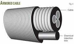
To minimize possible damage to the cable during gas-lift operations, the design includes a lead cable (Fig. 4). Lead is a physical barrier, preventing gas from getting into the insulation. The lead cable is AWG 1/0 dual armor and includes a capillary line for chemical injection.
Chemical injection
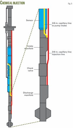
Fig. 5 shows the chemical injection for preventing scale formation, reducing foamy effects, and emulsions. The system injects the product directly at the pump intake to avoid as much as possible chemical contact with nonmetallic materials of the ESP (especially from the motor and seal section).
At the base of the ESP is a 23⁄8-in. check valve.
Based on a presentation to the Deep Offshore Technology International Conference & Exhibition, Houston, Feb. 12-14, 2008.
The authors
Marcos Pellegrini Ribeiro is currently a research project coordinator and technical consultant with Petrobras R&D center, CENPES. He previous worked for General Electric as a robotic and automation specialist. His current work involves designing and specifying ESP equipment as well as coordinating subsea ESP system development projects. Pellegrini holds a BSc degree in mechanical engineering from the State University in Rio de Janeiro, an MSc from the Federal University in Rio de Janeiro, and a PhD from Imperial College in London.
Giovani Colodette is a petroleum engineer for Petrobras and works on artificial lift and flow assurance for new projects and technologies. Colodette has a civil engineering degree from Universidade Federal do Espirito Santo (UFES).
Ignacio Martinez is a project manager Baker Hughes Centrilift for the Latin-America region. He is dedicated to offshore and subsea ESP projects off Brazil and Mexico. Martinez has a mechanical engineer degree from Universidad de Oriente, Venezuela.
Leandro Neves is a sales and marketing Manager for Baker Hughes Centrilift. Prior to his current position, he held various engineering and managerial positions with Centrilift. Neves has a BSc in mechanical engineering from CEFET University, Brazil, and a petroleum engineering degree from PUC University, Brazil.
