Neutron diffraction and small-angle neutron scattering techniques can assess residual stress in and the microstructure of hydrocarbon pipelines. Forecasting tools based on predictive failure models incorporating these techniques can produce such tangible benefits as improved material selection and pipeline design, greater standardization of material, and more thoroughly examined welding requirements.
They can also allow a more comprehensive understanding of ideal wall thickness, taking into account that thinner pipe walls can reduce RS gradients that cause failures while also reducing installation and material costs. Such tools will also help operators prioritize maintenance, repair, and rehabilitation needs.
Neutron techniques are also complementary to other testing methods, extending their benefit to pipeline operators by revealing hidden cause-effect relationships leading to pipeline failures and identifying potential weaknesses in protection systems.
This article explains how ND and SANS techniques can address problems in current pipeline-integrity assessment methodologies.
Background
Guaranteeing pipeline structural integrity requires pipeline operators to maintain a low likelihood of failures while at the same time keeping operating and maintenance costs under control. The operator’s ability to prevent failures through effective predictive models and appropriate inspection determines whether a low failure rate will be achieved.
The presence of a microcrack due to the welding process can lead to failure of the entire structure. An accurate method of assessing residual stress in pipelines can help address this and achieve desired safety and reliability levels.
Knowledge of RS levels and other microstructural factors (e.g., inhomogeneities, precipitates, microvoids, etc.) can help in selecting pipe manufacturers, specifying quality of materials, establishing safe operating pressures, and planning maintenance and rehabilitation programs.
RS in pipelines generally arises from material history, production, ground movement, and in-service damage. Extrusion, filament winding, thermal treatment, and welding processes are able to induce RS, which subsists without applying external load to the material. Estimating the real total stress when a material is subjected to external loads requires accounting for the underlying RS state. Some components of combined total stress may exceed a particular design stress limit of the material, risking an early structural failure.
Knowledge of spatial and directional RS distribution in pipelines becomes necessary to determine their influence on the material. The assessment of RS levels reveals, through ND and SANS tools, the cause-effect relationships between the current condition of a given pipeline material and its potential future failure modes under operating conditions.
Understanding such relationships permits predicting what types of failure modes are likely and the resistance of the pipeline material to crack propagation under operating conditions. Building a valid predictive failure model, however, requires considering valid methods of collecting material samples, cataloguing, and data analysis, which exceed the purpose of this article.
SANS should complete information obtained by the ND tool as it provides additional data characterizing defect type, amount, and size. SANS allows microbeam scanning and detection of nanopores (nanocracks) in sample materials. SANS analysis of samples exposed to different mechanical loads provides information on the nanoscopic and microscopic development of defectsfrom dislocations to voids and cracksand their relationship to applied stress. Comparative analysis between the SANS cross sections of freshly prepared and aged samples also provides information on size distribution and concentration of new defects induced by treatment of the material.1 2
Experimental procedure
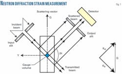
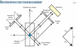
Strain measurement diffracts a collimated neutron beam (having a wavelength λ) with a polycrystalline sample, and then passes it through a second collimator before reaching the detector. Both collimators’ slits define the investigated volume (Fig. 1), whose cross section normally can be as small as 1 sq mm or, in individual cases, smaller.
The Bragg law (Equation 1) allows determining the interplanar distance dhkl. Equation 2 provides the corresponding lattice strain.
Analysis of triaxial stress requires particularly accurate values describing unstressed lattice spacing. A strainless sample of the material avoids systematic errors in the d0, and therefore in the strain value as well. Various experimental and analytical methods exist for the determination of d0,3 with Reference 1 discussing the representative geometry of diffraction related to pipelines (triaxial stress states).
Knowing the elastic constants of the material and applying the relations shown in Equation 3 yield the stress values.
Analysis of the shape of broadened diffraction profiles guides investigation of microstrains.3-5
RS measurement by ND present is nondestructive and provides precise statistical information by averaging measurements across a macroscopic sample volume. Investigation of a specimen can occur various times after exercise or heat treatment, and the small absorption of neutrons often allows measurement of centimeter-thick materials.
Operators can perform the same measurement on pipelines before and after heat treatment or welding process, and after different exercise periods, and points of the pipe can be investigated at different depths. The neutron beam can also perform deformation tests in situ, enabling both tensile and compressive tests up to a certain maximum loading.
SANS technique allows characterizing materials in the nanoscale (0.001-0.1 µm), is nondestructive, and provides precise statistical information by averaging data across a macroscopic sample volume. The specimen can be investigated various times after more exercise or heat treatments, and the small absorption of neutrons, often allows the measurement of centimeter thick materials.
Thermal treatment due to welding produces growth of inclusions (precipitates). SANS obtains their characteristics (number and size distribution) by knowing their chemical nature (e.g., carbides, etc.). Once a sample is investigated from the original material, investigating other samples taken after the material has been exercised, including the welded part, can check for microstructural changes (nanodefects, voids, etc.).
Obtainable results
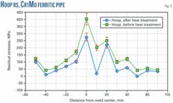
Fig. 2 represents hoop RS measured by neutron diffraction in a 2.25 Cr1Mo ferritic arc welded pipe before and after relaxation heat treatment (5-mm depth). The gap between the RS curves explains the resulting deviation trend between heat-treated and nonheat-treated samples.
The predictive model attempts to characterize the measured deviations between RS curves for different installation and operating conditions of the samples studied in the case of thermal-related failures. The gradient of the difference between RS curves, along with factors such as cycling fatigue caused by operating conditions, also factors into these deviations.
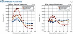
Fig. 3 represents the stress status in AISI 304 welded plate along the three main directions and plate thickness before and after a 620° C. thermal treatment.
Stress failure modes fall into two groups: thermal and mechanical. These categories, however, are not exclusive. In the case of welded pipes, for example, both thermal and mechanical-related stress exists, accelerating ageing. Any predictive failure model needs to account for the combined effects of thermal and mechanical-related failures, as well as their causes.
SANS provides much information on the nanostructure of a metal and its joints, and the results obtained help predict joint quality changes.1 2
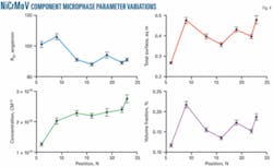
Fig. 4 shows variations of micro-phase parameters obtained by SANS in a very thick NiCrMoV steel component (94% Fe). Analysis of precipitates’ gyration mean radius, concentration, metal carbide interface area per unit volume, and volume fraction, can help determine the behavior of the exercised (exposed to thermal and mechanical stresses) material. These parameters represent the degradation level of materials, also relevant in determining the root causes of stress.
Thermal treatment during manufacturing for exampleheating at high temperatures, especially for a relatively long timepartially dissolves the material’s particles, saturating the solid solution. Cooling prompts growth of the precipitates from the saturated solution. The particles’ growth caused by high temperature can induce a coarsening of microstructure and further growth of the precipitates. Evaluating the shape and size of such precipitates therefore can prove particularly useful in locating areas of maximum thermal alteration and evaluating the velocity of said alteration.
The most important problems related to a material’s strength deal with welded metals, the fracture risk of which seems to be much higher than the base metal. Nonuniform mechanical stress and other aging factors (thermal treatment, fatigue, corrosion, etc.) create the higher risk of fracture in joints.
Current concepts of metal fracture, including welded joints, are based primarily on optical and electron microscopy data of surface structures or defects in thin slices. Research in fractography has focused on scanning electron microscopy to quantify features in the nonplanar fracture surface. The characteristics that unlock these quantitative data, however, are the true fracture surface areas.
Experimental procedures have advanced for obtaining the surface area (e.g., analysis of the resulting profiles related to the fracture surface). Fracture studies have also focused on the fractal properties of profiles and surfaces.
Fractal dimensions stemming from these analyses of observed nanoscale structures appear to be normally applicable to natural irregular nonplanar surfaces. Two main classes of fractal structures exist: aggregated clusters of small particles (volume fractals) and systems with irregular interfaces and grain boundaries (surface fractals). SANS measurements verify the fractal nature of structures and find their fractal dimensions.
Parameters usually adopted by the pipeline operator to ensure safe operations through the plant’s life suffer from a lack of data. Outstanding mechanical properties of the materials depend strongly on precipitates morphology and applied heat treatment. Transmission electron microscopy serves as the standard means of studying the morphology, although this and other standard methods of materials science do not allow for characterizing the microstructure completely.
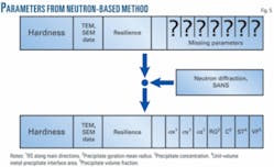
Precursory use of ND and SANS tools allows control of the micro and nanostructure determination of pipeline materials, enriching the available data set by supplying fundamental parameters. Fig. 5 shows the additional parameters that help understand and ultimately predict the degradation of materials, their possible fracture, and anticipated lifetime.
The proposed forecasting failure model will determine RS and remaining material life with relatively simple pattern matching techniques of actual pipeline data against the previously identified patterns. The two main sources of the model’s data are design data and data obtained from the ND and SANS tests.
The model allows prediction of behavior of the considered material under different scenarios. If current mechanical stress conditions continue, for example, the material will suffer a particular defect; or the cycling fatigue process coupled with thermal-related RS can cause a material fracture if cycling conditions continue.
Characterizing the gap between stress status estimates and maximum allowable stress values for the material with different scenarios also allows determination of remaining life. Other important features of the proposed predictive model include identification of probable causal factors of failures and the ability either to eliminate such causal factors or mitigate the resulting problem.
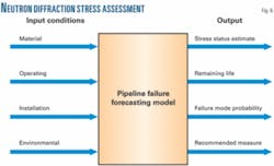
Fig. 6 shows a schematic diagram of the proposed forecasting failure model for pipelines.
The proposed forecasting model consists of a relational database formed by catalogued material parameters obtained from ND and SANS from samples that represent, statistically, the population of pipelines on which the forecasting tool will be used. Extended parameters obtained from ND and SANS include σx, σy, σz, RG, C, ST, and VF, which are cataloged along with conventional inspection TEM and SEM parameters and the operating, installation, and environmental conditions of both fresh and exercised (aged) pipe materials.
Studying and characterizing deviations between fresh and exercised samples yield a set of deviation patterns. Characterization includes recording and analysis of trend and inflexion points of the data curves to determine possible failure modes and remaining life.
The forecasting failure model considers material conditions, including material composition, measured wall thickness, corrosion level, presence and amount of welded joints; operating conditions, including presence and magnitude of applied forces, fluid pressure, historical accumulated stress (default value as a function of time), fluid properties, corrosion inhibitor chemicals, presence and magnitude of mechanical vibration; and installation conditions, including depth of burial, soil load, coating type, and cathodic protection, if any.
Environmental conditions considered include soil type, seismic level, rain, washouts, and maximum-minimum ambient temperature values.
References
- Rogante, M., “Neutron Examination Techniques Applied to Pipelines,” Oil & Gas Journal, Sept. 26, 2005, p. 59.
- Rogante, M., “The Application of Neutron Examination to the Pipeline Industry,” The Journal of Pipeline Integrity, Vol. 4, No. 4, 2005, pp. 211-218; Global Pipeline Monthly, Vol. 2, No. 1, January 2006, pp. 1-7; Petroleum Abstract, Vol. 46, No. 35, 2006, Abstract No. 903835, p. 81.
- Rogante, M., “The Stress-free Reference Sample: The Problem of the Determination of the Interplanar Distance d0,” Physica B: Condensed Matter, 2000, pp. 276-278.
- Noyan, I.C., Cohen, J.B., “Residual Stress Management by Diffraction and Interpretation,” Springer-Verlag, New York, 1987, p. 276.
- Rogante, M., “Caratterizzazione, mediante scattering neutronico, di materiali e componenti per l’impiantistica nucleare ed industriale,” Nuclear Engineering PhD, University of Bologna, Italy, 1999, p. 223.
Based on presentation to the Pipeline Rehabilitation & Maintenance conference, Manama, Bahrain, Dec. 11-13, 2007.
The authors
Pablo Genta ([email protected]) is a process control engineer at Saudi Aramco with experience in design, start-up, and operations of control systems in the oil, gas, and petrochemical plants and pipelines in the Middle East and the Americas. He has worked since 1994 for various engineering companies in the oil and gas sector, joining Saudi Aramco in 2003. Genta earned an MS in electrical engineering from the University of Buenos Aires, Argentina (1993).
Massimo Rogante ([email protected]) is a mechanical engineer and director of Rogante Engineering Office, Civitanova Marche, Italy. He earned a PhD in nuclear engineering from the University of Bologna, Italy (1999) and an MS in mechanical engineering from University of Ancona, Italy (1984). Rogante is a member of the International Scientific Advisory Committee of the Budapest Research Reactor and serves on editorial boards of a variety of scientific journals.
