Baseplate stops wellhead movement in Libyan oil field
Installation of a baseplate stopped wellhead movement on wells drilling in the Eastern Libyan Desert. Arabian Gulf Oil Co. operates the wells.
For drilling most of the wells, the company used rigs with a limited 19-24 ft substructure height. The work required a 4-ft cellar, dug prior to spudding the wells, to accommodate the blowout preventer stack.
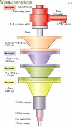
Fig. 1 shows a typical wellhead used in the area. The cellar houses Section A (13 5/8-in., 3,000 psi) and Section B (13 5/8 × 11-in., 3,000 psi) of the wellhead.
The 13 3/8-in. surface casing, cemented to surface, serves as pile anchor to support the landing weights of subsequent casing and liner strings. Because of insufficient cement slurry volume, slurry channeling, or cement deterioration over time, the casing can become unable to support the aggregate wellhead landing weight, subjecting the wellhead to:
- Vertical movement because of thermal expansion during production periods, thermal contractions during shut-in periods, and subsidence due to unsupported casing
- Horizontal movement because of unsupported surface casing down to a certain depth. In some cases, wellhead subsidence was 2 ft and would increase if not stopped.
These wells produce with natural flow or artificial lift with electric submersible pumps (ESPs)
To stop the wellhead movements, AGOC incorporated a baseplate at the wellhead to reduce loads on the wellhead.
Baseplate design
Sizing the baseplate requires taking into account the wellhead load, which is the aggregate weight of all casing and tubing landed on Section A of the wellhead and with an allowance for the buoyancy factor. The following relationship will determine the area of the baseplate, which is set level on desert sand:
ABP = (F × GWH)/Bs
The terms in the equation are as follows:
- ABP-Baseplate area (unit area).
- F-Fraction of the wellhead load to be transmitted to baseplate support area (0-1).
- GWH-Wellhead load (unit weight).
- Bs-Soil bearing capacity (unit weight/unit area).
The well’s drilling history will contain the intermediate and production casings’ landing weights, normally landed as cemented.
The production liner, if any, hangs inside the intermediate casing before being cemented and its weight is also in the well’s drilling history.
GWH also has to include the weight of the production tubing.
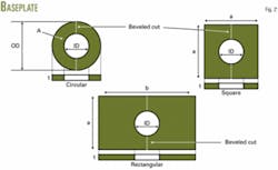
After calculating ABP, one needs to determine the optimum shape (circular, rectangular, or square) of the baseplate (Fig. 2). The available surface area around Section A allows for an annular shape circumscribing the surface casing.
Baseplate installation
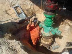
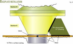
Installation of the baseplate involves digging around the wellhead down to just below Section A (Fig. 3). The excavation needs to expose the surface casing and the ground around it so that the soil just below Section A can be carefully leveled and compacted.
After determining ABP, one can start preparing the plate with an inside cut slightly larger than the casing (OD + 1 in.) before cutting it into two equal halves, with a bevel for welding. The plate then can be installed around the wellhead, just below Section A.
Welding the two halves together again forms one solid plate. The welding beads should be sufficiently thick and applied carefully so that the plate will not bend upwards during the welding. This plate must remain floating relative to the surface casing.
Six support wings welded to Section A allow for load transfer. One side of the wing plates are welded to Section A, while the other side is welded on the top side of the baseplate (Fig. 4).
The welding procedure of the wing plates should be such that it prevents damage from excessive localized heating to Section A and its internal parts, such as the casing hanger.
The author
Wathik M. Alhashimi is a senior engineering specialist-drilling, completions, and workovers-for Arabian Gulf Oil Co., Benghazi, Libya. He resides in Calgary. Previously he worked in management and engineering for several other petroleum and oil field service and supply companies in Canada, South America, and the Middle East. Alhashimi holds an MS in petroleum engineering from the Petroleum, Gas, and Geology Institute, Bucharest. He is a member of the Association of Professional Engineers, Geologists, and Geophysicists of Alberta.


