Controlled emergency shutdown procedures aid crude line safety
Pipeline control center operators need controlled operational emergency shutdown procedures to prepare for an emergency situation. The procedures contain the particular operational measures for each location of the pipeline system to be initiated using remote control (supervisory control and data acquisition or other control system). Integrating these procedures in a geographical information system data warehouse provides a combination of information sources for a state-of-the-art control center tool based on a modern information technology infrastructure.
Even if the operator never executes these procedures, they provide a good training tool for control room operators, demonstrating the proper bases on which to initiate the correct emergency procedure in a timely manner.
Calculating theoretical oil spill quantities for each pipeline section (based on the total drain down volume of the isolated block valve sections), provides the initial basis for a COESD procedure. The COESD section plan then graphically presents the calculated results with the pipeline elevation profile. The COESD section plan and available remote control devices (block valve stations, pump stations, relief tanks) define the COESD procedures to further minimize a potential oil spill in an emergency. Integrating COESD section plans and procedures within sophisticated GIS systems provides main control center operators with straightforward access to these procedures.
Background
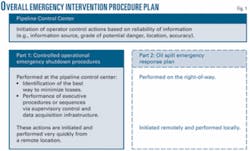
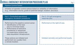
COESD procedures form the first part of the overall emergency intervention procedure plan mandatory for every oil pipeline. The COESD procedure contains mainly remote-controlled operational actions. The second part consists of the oil spill emergency response plan, which lies outside the focus of this article.
Fig. 1 provides an overview for the organizational implementation of COESD procedures.
The release of COESD procedures has priority over the release of an oil spill emergency response plan. The release of both plans, however, may occur simultaneously so long as this does not delay the COESD.
Shutdown criteria
The two general classifications of shutdown include a normal (operational) shutdown and an emergency shutdown.
A normal shutdown occurs upon either operational instructions or detection of failure or faults on safety equipment. A COESD occurs upon detection of leaks or suspected leaks or in case of danger or potential damage.
Emergency shutdowns usually cause higher operational load variations, subsequent operational faults, and longer downtimes, leading to higher costs than normal stops. Management should therefore develop clear-cut operating instructions enabling the responsible operator to correctly decide if an emergency shutdown is justified.
Leak identification
Human beings on any location along the ROW or in its surroundings can visually identify a leak, or the activation of the safety equipment in the control centers can alert the operators to a leak. A modern data warehouse system can combine various information sources and support the control center operator. The following paragraphs provide a listing of various specific identification mechanisms.
A company’s own personnel can inform the control center, which then implements all further measures as appropriate in accordance with its overall emergency intervention procedure plan. The staff’s familiarity with the pipeline system and its potential risks allow reliable identification of the pipeline marker or pipeline crossing from the control room.
A person outside the company can inform the pipeline control center or a public emergency call center. The control room operator then must verify if the problem is related to the pipeline system and cross-check whether the reported location matches a location along the pipeline system.
A leak detection system can also identify a leak. The typical LDS software package facilitates and integrates various leak detection monitoring methods to identify different kinds of leaks (small, midsized, or large leaks; slowly or rapidly developing leaks) across several operational scenarios (steady state, transient, or shut-in). Comparing the results of various algorithms can also validate a given alarm and exclude false alarms. Confirming alarm leaks also requires the control center to closely monitor and analyze all other pipeline systems presenting relevant information.
Leak locating
When a leak is first identified, it is unlikely its precise location will also be instantly known. For example, a person external to the company reporting a leak would likely refer to the neighboring villages, roads, rivers, or railways and would not normally be in a position to cite a pipeline kilometer or identify the appropriate valve stations.
Even when a leak is first detected in the control center, the leak-detection system may not always be able to sufficiently define the leak position immediately.
This is especially the case if the volume-mass balance method reports a difference in quantity and no other leak detection system alarm triggers at the same time. Provided it is not a false alarm (an instrumentation failure, faults in transmission, or errors evaluating the measured values), the leak could be at any point between the two mass metering devices.
Drafting a COESD procedure therefore requires accounting for any uncertainty about the location of an existing leak.
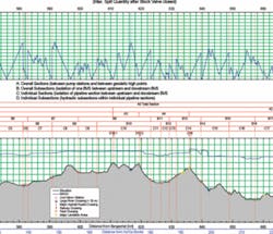
The COESD section plan (Fig. 2) provides an overview for identifying the proper COESD procedure. The section plan divides a pipeline system into main sections (A, B, C, etc). These main sections extend between the pump stations, pigging-relief stations, and receiving terminals.
Each number (x) after the letter designates other subsections within the plan and allows greater precision in determining a location along each section.
Subdividing the Ax sections into Ax.y sections between geodetic high points and other points of technical interest (e.g., pigging stations), allows for still greater accuracy. Further dividing each Ax section into Bx.y section isolates blocks or check valves along each section.
The first number (x) of the Bx.y sections is always in line with the overall Ax section, identifying the location, while the second number (y) identifies the sequence.
Subdividing each Bx section further into Cx.y sections, isolates pipeline sections between the next upstream or downstream block or check valves.
The first number (x) of the Cx.y sections is always in line with the overall Ax section, identifying the location, while the second number (y) identifies the sequence.
The COESD section plan also divides the pipeline into Dx.z sections based on hydraulic criteria and on the possibility of draining, using existing mechanical connections, into mobile storage equipment or using mobile pumps to transfer around closed block valves to a neighboring section. The second number (z) of a Dx.z section is in line with the sequence number (y) of the superior Cx.y section.
The section plan also shows the theoretical oil spill quantities. Total drain-down values of the isolated block-valve sections provide the basis for these quantities. The drain-down values would remain valid in case no COESD procedure were carried out in time or at all. The section plan also calculates the maximum possible spill quantity for each section and each elevation point.
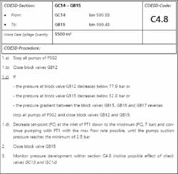
The COESD section plan subdivides A-sections into B, C and D-sections (Fig. 2). The control center operator should execute the dedicated COESD procedures as quickly as possible (Fig. 3).
Figs. 2-3 show COESD as applied to the 1,765-km, 34-46 in. OD, Baku-Tbilisi-Ceyhan crude pipeline, which began operations in 2006.
The subdivisions allow the responsible operator, depending on the level of information available, to identify pipeline sections of interest, while automatically ensuring maintenance of optimum operating parameters. The section of interest is always the smallest section the section plan can identify.
If the operator gains additional information at a later stage and knowledge of the actual leak location is improved, the operator shall immediately take necessary corrective actions to reduce the previously selected pipeline section.
COESD implementation
In the event of an alarm, the operator identifies the section of the pipeline in the overview section plan (Fig. 2) in which he can already locate the leak on the basis of initial information or suspicions. The section codes shown in the overview section plan for the sections on which damage is suspected describe the particular measures to be taken. These measures are defined in the catalogue of COESD procedures to be executed (Fig. 3). Depending on pipeline length and elevation profile the number of individual COESD procedures could easily reach 400 or more.
The individual sections of the pipeline covering the threat location, as identified on the section plan, should always be as short as possible.
Besides the code number in the COESD procedure heading of each section, the catalogue of COESD procedures also shows the type of station or important hydraulic points and their location in total pipeline kilometers for the beginning and the end of each section.
The procedure heading also shows the worst-case oil spill within sections B, C, and D. The actual scale of any spill depends on the exact location of the leak.
When completing measures for individual sections described in the catalogue of COESD procedures to be executed, operators must adhere strictly to the specified control sequence.
COESD example
In order to assist the pipeline operator in a timely manner, especially in emergency situations, COESD procedures should be easily accessible within a modern electronic database. The database tool should provide quick access to relevant COESD section plan drawings as well as to the identified COESD procedures. Combining the COESD procedures and section plans with other information sources and databases inside a GIS data warehouse provides the control center operator with a powerful tool.
A simple Microsoft Office database application can provide this functionality early in a project (e.g., during pipeline commissioning or line-fill activities). During operation, however, the database must also support cross-references with other geographical pipeline information (e.g., maps with pipeline markers, right-of-way records, a land registry database, etc.), requiring use of a modern GIS system.
null
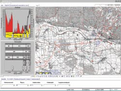
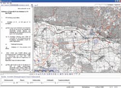
The pipeline-specific requirements of the operator typically guide design of this kind of system. Figs. 4-5 show screenshots from the 348-km, 28-in. OD, Mid-European Crude Oil Pipeline, running between Vohberg, Germany, and refineries in the Czech Republic. MERO used ms.GIS software to implement COESD procedures within a GIS data warehouse system.
The right side of Fig. 4 shows a map for a selected pipeline section. The bottom part of the display shows various filter options available for a quick pipeline section allocation, depending on information available to the control center operator. The left side shows the COESD section plan provided for the selected section.
Selecting the relevant COESD procedure occurs directly within the COESD section plan. The software presents the COESD procedure to the operator on a separate register tab as a part of the left frame (Fig. 5).
The author
Tobias Walk is deputy head of the department of SCADA & automation at ILF Consulting Engineers GMBH, based in Munich. Recent projects of note include design of the automation concept for the East Siberia Pacific Ocean crude oil pipeline system (2007-present) and design, construction, and commissioning of the Baku-Tbilisi-Ceyhan crude oil pipeline system (2001-06). Walk studied electrical engineering and information technology at the Technical University of Munich, with special focus on automation and control systems, graduating in 1996.
