SPECIAL REPORT: CORROSION MODELING—1: Model predicts internal pitting corrosion of oil, gas pipelines
Laboratory experiments and observation of pit growth rates in six operating fields have yielded a model to predict internal pitting corrosion of oil and gas pipelines. The experiments occurred in a simulated high-pressure, high-temperature environment, while field observations took place for 4 years. The model works for transmission pipelines and sour or sweet production lines.
This first part of two articles examines the pitting corrosion mechanism as well as problems in predicting internal pitting corrosion of oil and gas pipelines, before beginning an assessment of the parameters that influence internal pitting corrosion.
The second, concluding article (OGJ, Dec. 3, 2007) will continue this assessment and discuss both the predicting model and its validating observations.
Background
Pipeline design requires calculation of a minimum required WT based on appropriate standards.1-3 This minimum calculated wall thickness includes two parts: pressure containment and corrosion allowance. Corrosion allowance normally accounts for the part of the pipe wall thickness required to compensate for loss due to corrosion. Either the predicted corrosion rate and design life of the pipeline or experience set the corrosion allowance.
Prediction models incorporate the effects of factors that influence corrosion inside a pipe. A true industry standard approach to predicting pipeline internal corrosion does not exist, although there are aspects of commonality between the models offered by a number of operators, research organizations, and academic establishments. A previous publication presents an overview of various corrosivity models.4
Most of the internal corrosion of oil and gas pipelines occurs through localized attack, characterized by loss of metal at discrete areas of the surface with surrounding areas essentially unaffected or subject to general corrosion.
These discrete areas may take various geometrical shapes. Circular depressions, usually with tapered and smooth sides, are pits. Stepped depressions with a flat bottom and vertical sides are mesa attack. Other geometrical forms of localized corrosion include silts (sometimes referred to as knife line) and grooves.
In flowing conditions, localized attack may take the form of parallel grooves extending in the flow direction. This phenomenon is known as flow-induced localized corrosion.5
Corrosivity models have contributed to our understanding of the effects of chemical, physical, mechanical, and other forces on the corrosion conditions inside the pipe, but they do not predict localized pitting corrosion, the main failure mechanism of oil and gas production and transportation equipment.
This article presents a practical model to predict internal pitting corrosion of oil and gas pipelines and uses data obtained from an operating field to validate the model.
Mechanism
The penetration of a pipe wall by a pit consists of three stages:
- Formation of surface layers on the steel surface.
- Initiation of pits at localized regions on the steel surface where layer breakdown occurs.
- Pit propagation and eventual penetration of the pipe wall.
Surface layers generally form as bilayers, with a compact layer adjacent to the metal and an outer layer consisting of a precipitated phase that may incorporate anions or cations from the solution (salt film).
Much debate concerns the initiation of pitting corrosion. One approach places emphasis on inherent microscopic defects of the metal surface: inclusions, grain boundaries, and scratches, with the other typical approach holding that nonuniformity on the surface layer occurs after its formation by solution species.6
Propagation pits make up the final stage of pitting corrosion. When pits become sufficiently large they continue to grow until failure occurs, although the growth rate will sometimes accelerate (autocatalytic process) or decelerate (dormant pits).
Pitting corrosion, therefore, does not occur as a continuous process but rather in various steps; the process is stochastic or random.7
The depth of a corrosion pit depends on the pit’s growth rate and the timing of its initiation.
Prediction problems
The problems in developing an internal pitting corrosion model for oil and gas pipelines are twofold:
- Development of a scientifically reliable pitting corrosion model to predict the performance of the pipes.
- Availability of inputs from the operating pipelines to use in the scientific model.
Field operating conditions should predict pipeline performance. An apparent trade off exists, however, between the scientific accuracy and ease of use of a model and the availability, reliability of details, and accuracy of input data. The main purpose of any model is to predict logically, scientifically, and, from the perspective of the field operators, in a user-friendly way, the probability of internal pitting corrosion under the operational conditions as defined by the inputs.
Only parameters considered essential in the design of pipelines and that are readily available from the operating conditions should be used as inputs to the model.
These parameters include:
- OD.
- WT.
- Steel composition.
- Pipe orientation.
- Oil chemistry and production.
- Water chemistry and production.
- Gas chemistry and production.
- Presence of solids.
- Temperature.
- Pressure.
- Partial pressures of acid gases (CO2 and H2S).
- Pipe operating schedule.
Pitting parameters
Laboratory and field experiments developed a model to predict internal pitting corrosion under pipeline operating conditions. The laboratory experiments used realistic pressure and temperature conditions of oil and gas producing pipelines, gathering the oil and water samples required for this purpose from the field. Field experiments also occurred in six operating pipelines.
Previous publications described details of the experimental procedure and analysis of laboratory and field experiments.8-18 The following paragraphs present salient features.
The internal surface of a pipeline is susceptible to corrosion. Dissolving the products of corrosion in the environment leads to a uniform corrosion rate; i.e., general corrosion will occur. If the corrosion product forms intact layers that cover the surface (commonly known as surface layers), the corrosion rate will decrease to a minimum.
Neither of the two extreme conditionsuniform corrosion or formation of an intact, compact, and protective layergenerally occurs. In practice, the following sequence of events leaves the pipe susceptible to pitting corrosion:
- Surface layers (single or multi) form due to corrosion of metal exposed to the environment.
- In the event of a breakage of the surface layer, corrosion reactions taking place at the steel surface continuously reinforce the surface layer.
- Under operating conditions of oil and gas pipelines, a combination of any or all of the three following surface layers is possible: iron oxide, iron carbonate, and iron sulfide.
- Surface layers are removed at localized areas of the steel surface but left on the rest of the surface.
- Areas where the protective layer is removed become anodic (with respect to the rest of the pipe).
- The surrounding areas become cathodic.
- The corrosion reaction taking place at the localized anodic areas is insufficient for complete reformation of surface layer.
Once this sequence of events occurs, pits initiate, propagate, and failure eventually occurs. The probability and rate of pitting corrosion depend on the stability of the local anode and bulk cathode and their relative areas. Complete removal of the surface layer may be beneficial because the anode and cathode ratio become uniformly distributed, resulting in uniform corrosion (as opposed to pitting corrosion).
Parameters influencing the preceding sequence are extensive but fall within the following three categories:
- Construction.
- Operational.
- Computable.
Construction parameters
Construction parameters include steel grade, pipe diameter, initial pipe thickness (ID and OD of the pipe), and pipe orientation. Construction parameters do not vary with time.
• Steel. Minor alloying elements can profoundly affect the susceptibility of a metal or alloy to localized corrosion, including pitting. The most important element is molybdenum, which, when added at a concentration of a few percent, causes a significant decrease in the breakdown of passive layer.
Not all minor alloying elements, however, are beneficial. For example, adding sulfur to carbon steels, particularly those containing manganese, increases the susceptibility of the resulting matrix to localized attack.
In general, the presence of a micro-alloying element anodic to carbon steel on the steel surface increases the possibility that the passive layer formed on top of the micro-alloying element is unstable, producing a pit-initiation susceptible area (an area susceptible to the initiation of an anodic site, leading to the stabilization of smaller local anodic areas surrounded by larger cathodic areas.) Although carbon steels (iron with <1% carbon and varying amounts of Mn, S, P, Si, Cu, Mn, Si, Ni, and Cr) differ in composition, their corrosion performance is similar.19
• WT. The industry has established nominal thicknesses for various steels and pipe diameters. Conditions in which the risk of or effect of failure is high call for pipes with increased WT to be used.
• Pipe orientation. Topography causes pipes to be laid at various orientations, with angles of 0-90°. Laying the pipes at various orientations does not increase or decrease the probability of pitting. But pipe orientation does affect the flow pattern and deposition of solids, thus indirectly influencing the location of pitting corrosion.
Operational parameters
Operational parameters include production rates of oil, water, gas, and solids, temperature, pressure, partial pressures of acid gases (CO2 and H2S), and concentrations of sulfate, bicarbonate, and chloride.
• Oil. Wet corrosion is an electrochemical process requiring a conductive phase. The low conductivity of oil prevents corrosion from occurring on the surface wetted by oil.
The corrosivity of a crude oil depends on its chemical characteristics. In general, inorganic salts, sulfur content, organic acids, dissolved gases and water, solids, and paraffins determine crude’s corrosivity.
The degree of oil’s affinity to carbon steel yields three categories:
Oil-wet surface: The oil has a strong affinity to be in contact with carbon steel.
Water-wet surface: The oil has no affinity to be in contact with carbon steel. The oil may not be in contact with carbon steel at all, even when it is the only phase.
Mixed-wet surface: The oil has no affinity to be in contact with carbon steel. The oil may be in contact with the carbon steel surface as long as there is no competing phase present.
Previous publications describe methods to determine wettability.17-18
An oil-wet surface physically isolates the pipe from the corrosive environment. This condition makes establishing a low anodic localized area surrounded by larger cathodic areas difficult, decreasing the probability of pitting corrosion.
A mixed-wet surface physically isolates the pipe from the corrosive environment as long as the oil-to-water ratio is high. This condition makes establishing a low anodic localized area surrounded by larger cathodic areas less difficult, when compared to oil-wet surface, but the probability of pitting corrosion remains low. Susceptibility to pitting corrosion increases at the inversion point, when the water-in-oil emulsion becomes oil-in-water.
A water-wet surface (in the presence of oil) is highly susceptible to pitting corrosion. This condition makes establishment of a low anodic localized area surrounded by larger cathodic areas relatively easy, increasing the probability of pitting corrosion. The engulfing oil layer above the water layer facilitates localization and stabilization of smaller anodes surrounded by larger cathodes, increasing the probability beyond what is seen in the absence of oil.
Table 1 shows the experimentally determined variation in pit growth rates with oil types, holding all other factors equal.
• Water. There are two kinds of emulsion, oil-in-water and water-in-oil.
W-O emulsion has low conductivity and high resistance, making it less corrosive, while O-W has high conductivity and low resistance, making it more corrosive. The ratio of water-oil at which W-O converts to O-W is called the inversion point. Previous publications describe the methods used to determine inversion point.17-18
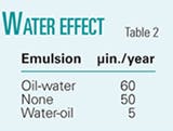
The higher conductivity of water means that the entry of any amount of water increases the probability of pitting corrosion, unless the oil emulsifies the water, creating a water-in-oil phase of low conductivity. Table 2 shows the experimentally determined variation in pit growth rates with water and oil emulsion, when all other factors are equal.
• Gas (flow). Introduction of gases can increase pitting corrosion by increasing turbulent flow. At the same time flow rate enables the gas to dissolve in the liquid (water). Acid gases such as CO2 and H2S are corrosive when dissolved in water.
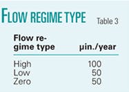
Table 3 shows the experimentally determined variation in pit growth rates with flow, when all other factors are equal.
• Solids. Solids have two detrimental effects.
In a low-flow regime, deposits may form on the surface and produce conditions for under-deposit corrosion. They also help establishment of areas conducive to the development of small anode-large cathode regions. In moderate flow conditions, solids may abrade the surface removing any protective build-up and leading to a surface profile conducive for pitting. Solids in higher-flow regimes also produce erosion-corrosion through abrasion.
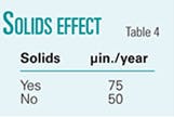
Table 4 shows the experimentally determined variation in pit growth rates with the presence and absence of solids.
• Temperature. Higher temperatures generally increase the corrosion rate by accelerating the electrochemical and chemical reactions. The rate of precipitation, however, also increases with temperature, reducing the corrosion rate when protective films are formed.
The influence of temperature on protective film formation is quite complex. For layers that physically adsorb into the metal surface, protection decreases with increasing temperature because elevated temperature facilitates desorption. For layers that chemisorb onto the metal surface, the chemical bond strength and the resulting protection increase with temperature up to a certain point, at which the thermal degradation of the layer occurs.
Increased temperature similarly increases the diffusivity of both pitting (e.g., chloride ions) and inhibitive (e.g., corrosion inhibitors, sulphate ions) species.
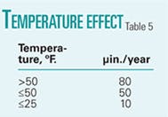
Table 5 shows the experimentally determined variation in pit growth rates with temperature.
Acknowledgments
The authors acknowledge the help and support of the members of the CANMET-Industry Consortium on Predicting Internal Pitting Corrosion of Multiphase Pipelines (Baker Petrolite, Devon Canada, Enbridge, Encana, ExxonMobil, Nalco, and PetroCanada). The Federal Interdepartmental Program of Energy Research and Development also supported this project. The authors also thank the numerous staff members at CANMET who participated in the project.
References
- Canadian Standards Association, Standard Z662.2003.
- Canadian Association of Petroleum Producers Technical Document, “Recommended Practice for Mitigation of Internal Corrosion in Sweet Gas Gathering System,” 2002-0013, February 2002.
- CAPP Technical Document, “Recommended Practice for Mitigation of Internal Corrosion in Sour Gas Gathering System,” 2003-0023, January 2003.
- Papavinasam, S., Revie, R.W., Friesen, W., Doiron, A., and Panneerselvam, T., “Review of Models to Predict Internal Pitting Corrosion of Oil and Gas Pipelines,” Corrosion Reviews, Vol. 24, Nos. 3-4, pp. 173-230, 2006.
- Kermani, M.B., and Smith, L.M.,” “CO2 Corrosion Control in Oil and Gas Production: Design Considerations,” European Federation of Corrosion Publications, Number 23, EFC, 1997.
- Sharland, S.M., “A Review of the Theoretical Modelling of Crevice and Pitting Corrosion,” Corrosion Science, Vol. 27, No. 3, p. 289, 1987.
- Okada, T., “A Theory of Pertrubation-Initiated Pitting,” Journal of Electrochemical Society, Vol. 132, No. 3, p. 537, 1985.
- Papavinasam, S., Revie, R.W., and Doiron, A., “Predicting Internal Pitting Corrosion of Oil and Gas Pipelines: Review of Corrosion Science Models,” NACE Corrosion 2005, Houston, Apr. 3-7, 2005.
- Papavinasam, S., Revie, R.W., and Doiron, A., “Predicting Internal Pitting Corrosion of Oil and Gas Pipelines: Review of Electrochemical Models,” NACE Corrosion 2005, Houston, Apr. 3-7, 2005.
- Papavinasam, S., Friesen, W., Revie, R.W., and Doiron, A., “Predicting Internal Pitting Corrosion of Oil and Gas Pipelines: Review of Corrosion Engineering Approach,” NACE Corrosion 2005, Houston, Apr. 3-7, 2005.
- Papavinasam, S., Doiron, A., and Revie, R.W., “A New Method for Pipeline Integrity Management,” Materials Performance, Vol. 46, No. 1, pp. 42-44, 2007.
- Papavinasam, S., Doiron, A., and Revie, R.W., “Integrity Management of Pipelines: Internal Corrosion Control,” NACE Corrosion 2006, San Diego, Mar. 12-16, 2006,
- Papavinasam, S., Demoz, A., Michaelian, K., and Revie, R.W., “Further Validation of a Pitting Corrosion Model,” NACE Corrosion 2008, (to be presented).
- Demoz, A., Papavinasam, S., Michaelian, K., and Revie, R.W., “Measurement of Corrosion Potentials of the Internal Surface of High Pressure Operating Oil and Gas Pipelines,” ASTM International (publication pending).
- Papavinasam, S., Doiron, A., Lafraniere, Y., and Revie, R.W., “Abnormal Internal Pit Growth Rate as Measured by Ultrasonic Measurement,” Materials Performance (publication pending).
- Papavinasam, S., Doiron, A., Panneerselvam, T., and Revie, R.W., “Effects of Hydrocarbons on the Internal Pitting Corrosion of Oil and Gas Pipelines,” Corrosion, Vol. 63, No. 7, p. 704, 2007.
- Papavinasam, S., Doiron, A., Panneerselvam, T., and Revie, R.W., “Predicting Internal Pitting Corrosion of Oil and Gas Pipelines: Hydrocarbon-Wet to Water-Wet Transition,” NACE Corrosion 2006, San Diego, Mar. 13-17, 2006.
- Papavinasam, S., Doiron, A., and Revie, R.W., “Empirical Equation to Predict Conditions for Solid Deposition,” Materials Performance, Vol. 46, No. 8, p. 58, 2007.
- Graedel, T.E., and Frankenthal, R.P., “Corrosion Mechanisms for Iron and Low Alloy Steels Exposed to the Atmosphere,” Journal of Electrochemical Society, Vol. 137, No. 8, p. 2385, 1990.
The authors
Sankara Papavinasam ([email protected]) is senior research scientist at CANMET Materials Technology Laboratory, Ottawa. He holds an MS from Madurai Kamaraj University, India, a masters of philosophy from Annamalai University, India, and a PhD from Bangalore University, India. He is a member of NACE, ASTM, SSPC, and the Electrochemical Society and is the current chairman of NACE STG 62 and ASTM G01.11.
Alex Doiron ([email protected]) is a corrosion technologist at CANMET, Natural Resources Canada, in Ottawa. He holds a BS in chemistry (with honors) from Carleton University, Ottawa (1999).
R. Winston Revie ([email protected]) is program manager, infrastructure reliability at the CANMET Materials Technology Laboratory in Ottawa, Canada. He has a BS from McGill University, Montreal, an MS from Rensselaer Polytechnic Institute, Troy, NY, and a PhD from the Massachusetts Institute of Technology, Boston. He is a fellow of NACE International, ASM International, and the Canadian Institute of Mining, Metallurgy and Petroleum.
Vladimir Sizov ([email protected]) is the group lead, facilities integrity at EnCana Oil & Gas, Calgary. He has also served as corrosion engineer at EnCana for the past 7 years. He holds a BS in mechanical engineering and an MS in material science (1993, 1999) from Moscow Power Engineering Institute and University of Calgary, respectively. He is a member of APEGGA, NACE.


