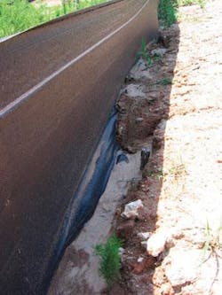
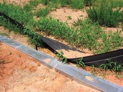
Researchers have developed an effective silt fence and mechanized installation system ideally suited for pipeline construction. Field testing of the system has shown it to be effective on slopes up to 20%.
Observational survey results for conventional silt fence in use for boundary sediment-control range between poor at best and outright failure.
Preliminary results from field testing show Failure Avoidance Effective Silt Fence Technology is more effective and durable than conventional silt fence for sediment control. Progress toward developing automated manufacturing and installation equipment is under way, with the objective of beginning commercial production in the near future.
Background
The configuration of pipeline and other linear construction sites creates erosion and sediment control problems not typically seen on conventional rectangular building lots. The limited width of right-of-ways limits the effectiveness of sediment traps and basins generally, forcing reliance on perimeter controls. Linear configuration also virtually eliminates any opportunity to install perimeter controls on the contour to increase their effectiveness.
The US Environmental Protection Agency consistently cites sediment as the primary pollutant of concern in runoff from construction sites.1 Increased sediment loads almost always cause degradation of streams and are also implicated in degradation of wetlands, estuaries, lakes, and reservoirs.2
The pipeline industry has responded to increased regulatory and public pressure in a variety of ways, including encouraging use of best management practices on pipeline construction sites. An example of this is Reasonable and Prudent Practices for Stabilization, promoted by the Independent Petroleum Producers Association.3
The guidance document outlining these practices presents decision trees for erosion and sediment control based on region of the US, slope, proximity to water body, and vegetative cover. In every case where erosion-control practices are deemed necessary, the document lists perimeter controls, silt fence, and straw bales as recommended practices.
The pipeline construction industry clearly has a strong interest in effective perimeter controls for pipeline construction sites. The nearly universal use of silt fence has generally yielded poor results. Improper installation, lack of maintenance, or installation on unsuitable sites, particularly those with steep or long slopes, has generally been the cause of failures. Field inspections conducted by Barfield and Hayes of more than 50 construction sites in South Carolina and Kentucky revealed silt fence was seldom installed according to standards and specifications and was frequently installed across contour.4
Undercutting of the toe, inadequate detention time, overtopping, and structural failure of either the fabric or posts are the common failure modes of silt fence. At moderately steep slopes, lateral flow along the toe of the fence can erode the toe trench and lead to undercutting failure. Settling of particles, not the fence acting as filter, is the principal mechanism for trapping sediment upstream of a silt fence. The fences instead act like permeable dams.
Most silt fence installations, however, do not provide adequate detention time for settling to occur. Flow concentration at low spots may lead to overtopping failure.
The pipeline industry benefits of a silt fence system resistant to undercutting when installed in uneven, hilly terrain, and able to provide adequate detention time without failure by overtopping are clear
Any of these modes of failure can currently occur even if current technology is properly installed.
Concept
One of the primary limitations of silt fence is the failure by undercutting and lack of detention caused by uncontrolled flow along the toe of the fence. To address this problem, Failure Avoidance Effective Silt Fence Technology includes a geotextile apron extending upslope of the toe and flow barriers spaced at regular intervals along the toe. The apron and vertical portion form a continuous geotextile surface to prevent scour under the fence. The flow barriers stop the flow, further preventing scour, and form impoundments to provide detention time and allow the sediment to settle.
An additional limitation of conventional silt fence is inadequate strength of fabric under incoming loads of water and sediment, resulting in excessive bulging, stretching, and eventual failure. The traditional response has been to require fabric be reinforced, typically with a wire mesh backing. The FAEST silt fence reduces spacing between posts, providing an equivalent gain in strength.
Most conventional silt fence, especially premounted fence, has post spacing of about 10 ft. Stapling the fence to the posts also creates stress concentrations and opportunities for tearing the fabric during installation.
The FAEST system uses 6-ft spacing, allowing the fabric to withstand water and sediment loads to a depth of at least 2 ft without failure. A combination of field testing and computer stress-strain modeling has verified these results. Clamping the posts to the fabric also occurs in such a way as to minimize stress concentrations.
A mechanized installation system capable of installing long lengths of fence (up to 1,000 ft) in a single pass requires folding and rolling the fabric onto a spool. It is not feasible to roll fabric with wire mesh and carry both on the installation equipment. Making an additional pass to add the wire mesh greatly reduces the advantages obtained by mechanized installation.
A final problem of conventional silt fence FAEST addresses is failure of wooden posts to remain erect in saturated soil conditions. The posts generally included with silt fence are pre-mounted 1 in. by 2 in. pine stakes that are easily damaged when driven into the ground. They also tend to rot and otherwise deteriorate in saturated soil.
Use of stronger oak posts that do not deteriorate rapidly partially solves this problem. If the soil is saturated, however, even oak posts may not remain erect. FAEST uses metal posts with vanes on the bottom to help stabilize them in saturated soil.
Metal posts are slightly more expensive but have two advantages which mitigate the extra expense: they can be recovered once the job is completed and reused and they can be easily driven into hard ground with a mechanized post-driver without being damaged. The mechanized FAEST installation system includes a post driver that sets the posts at the correct depth to ensure proper support of the fence.
Performance
The first round of field testing occurred under controlled conditions. Predetermined slopes, soils, and rainfall rate and duration determined FAEST’s ability to trap sediment under specific conditions. These tests finished in 2005.
The second round of field testing deployed FAEST at a landfill site in South Carolina. Deploying conventional silt fence provides a basis for comparison. Fence and monitoring equipment installation concluded in June 2007, and data collection is in process.
Controlled testing
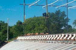
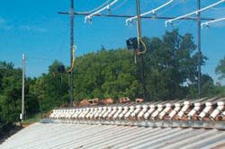
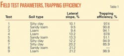
Controlled field testing of FAEST occurred at the USDA Hydraulics Laboratory near Stillwater, Okla. Test parameters represented extreme conditions for silt fence deployed in the field, including a rainfall rate of 2.5 in./hr and slopes along the toe of the fence ranging from 9.4 to 21.2%. Fig. 1 shows the test bed and rainfall simulator.
Testing used three different soils: sandy loam, loam, and silty clay. Monitoring for each rain event captured the amount of rainfall, sediment yield from the source area (which was worked to simulate a newly-graded construction site), and sediment discharged through the fence. FAEST demonstrated very good trapping efficiency (Table 1).
In field tests Nos. 5 and 8, scour occurred along the front (upslope) toe of the apron, causing a small gully to form which intercepted the flow before it entered the impoundments. This problem needs to be addressed for FAEST to work well in non-cohesive soils. Grading the soil at the front toe to force the runoff onto the apron and prevent the gully from forming emerged as the solution to this problem.
A need to prevent wind from blowing underneath the apron and displacing it also became apparent in the first round of field testing. Adding a back toe to anchor the apron and vertical portion of the fence prevented displacement of the apron.
The controlled field tests used metal posts and attached the fence to the posts with wire ties looped through openings in the fabric. Observation showed the fabric to be highly susceptible to damage from the ties, creating tears and openings through which excess sediment would escape. A modified post using a clamp applying continuous pressure along the entire height of the post solved the problem and held the fence in place.
Controlled field testing showed FAEST provides effective sediment control under conditions that would cause failure in a conventional silt fence.
Long-term performance
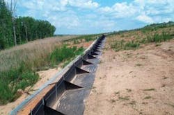
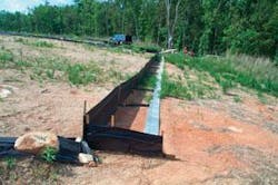
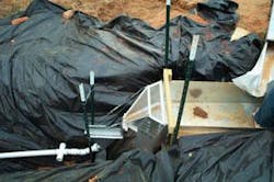
Fig. 2 shows the FAEST system installed on a landfill site in Greenville County, SC. Fig. 3 shows the conventional silt fence installed for comparison. The site used a tipping-bucket rain gauge to monitor rainfall. A calibrated H-flume measured discharge (Fig. 4). Once measured in the H-flume, the discharge passes through a flow diverter that transfers a representative portion of the discharge and sediment to a collection tank.
When rainfall of 0.25 in. occurs, the rain gauge sends an alert via cell phone to test personnel so that they know to visit the site. Rainfall needs to exceed about 0.5 in. before sufficient sample material can be obtained for laboratory analysis. Once at least 0.5 in. of head has accumulated on the H-flume, a pumping sampler begins operating, diverting discharge into 1-l. bottles.
The sampler obtains samples at 5-min intervals. Plans exist to reprogram the sampler to select a time interval based on the volume coming through the H-flume.
Removal of the trapped sediment accumulated behind the fence follows each event, with the weight of the removed sediment recorded and samples are taken for laboratory analysis of water content. This information yields the volume of sediment collected in the fence.
Discharge rates and concentrations determine the volume of sediment discharged through the fence and allow calculation of its overall trapping efficiency.
These data-collection processes occur for the instrumented portions of both FAEST and the conventional silt fence. Each sampling event is followed by a thorough cleaning of the collection gutters, flumes, and sampling tanks in preparation for the next event. A visit to check the site occurs once each month.
The instrumented installations will remain in place, and data collection continue, long enough to obtain data from three to five events greater than 2 in.
Laboratory analysis of samples from the first events is still under way.
Visual monitoring
Visual observations made to date confirm the FAEST installation is trapping much more sediment than the conventional fence. The FAEST installation also remains erect and is not undercut, while the standard silt-fence installation has undercut rapidly and overturned more than once.
Fig. 5 shows sediment accumulation in the FAEST installation. Fig. 6 shows the FAEST installation intact, with all posts erect.
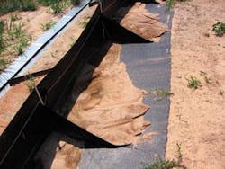
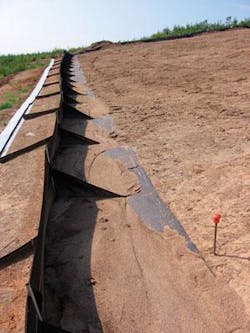
Figs. 7-8 show the damage sustained by conventional fence in the same storms. This damage occurred during rainfall events between June 14 and July 5, 2007.
null
null
Manufacture, installation
The Biosystems and Agricultural Engineering Laboratory at Oklahoma State University fabricated the FAEST fence deployed in South Carolina. Fabrication played an important role in FAEST’s development, generating information regarding manufacturing issues that might arise in commercial production.
The Charles Machine Works Inc. has developed a specialized vibratory plow that can rapidly and consistently bury the toe of a conventional silt fence at the proper depth. Modifications to the conventional silt fence installation machine are under way to add the ability to bury the front and back toe simultaneously as well as to drive steel posts to proper depth.
Acknowledgments
The authors thank the Integrated Petroleum Environmental Consortium and the US Environmental Protection Agency for funding, Oklahoma State University Department of Biosystems and Agricultural Engineering, and the US Department of Agriculture Hydraulics Lab for assistance in the field laboratory studies, and Greenville County, SC, and Woolpert Inc. for assistance in field monitoring.
References
- US Environmental Protection Agency, “Developing Your Stormwater Pollution Prevention Plan,” EPA 833-R-060-04, 2007.
- Clar, M.L., Barfield, B.J., and O’Connor, T.P., “Stormwater Best Management Practice Design Guide -Volume 1-General Considerations,” US Environmental Protection Agency, EPA/600/R-04/121, 2004.
- http://www.ipaa.org/issues/hot_topics/rapps.asp.
- Barfield, B.J., and Hayes, J.C., “Unpublished results of field evaluation of sediment controls in South Carolina and Louisville, Ky., construction operations,” J.C. Hayes & Associates, Clemson, SC, 1992 and 1997.
The authors
Ellen Stevens ([email protected]) is an assistant researcher at Oklahoma State University in Stillwater. She has also served as a civil engineer for Painter and Associates and the US Army Corps of Engineers. She holds a BS in civil engineering from WV University Institute of Technology, master of civil engineering from Mississippi State University, and a PhD in agricultural engineering from Oklahoma State. She is a member of ASCE, NSPE, and the Oklahoma Floodplain Manager’s Association and is a registered professional engineer.
Sandeep Yeri ([email protected]) is a senior programmer at Woolpert, Inc., Stillwater, Okla. He has also served as assistant researcher at Biosystems & Agricultural Engineering at Oklahoma State University. He holds a master’s in mechanical engineering from Oklahoma State University.
Billy Barfield ([email protected]) is a senior engineer at Woolpert, Inc, Stillwater, Okla., and professor emeritus in biosystems engineering at both Oklahoma State University in Stillwater and the University of Kentucky in Lexington. He holds BS degrees in civil engineering and agricultural engineering, and a PhD in agricultural engineering from Texas A&M University in College Station. He is a fellow of the American Society of Agricultural and Biological Engineering, a diplomat of the AWRE, a member of the American Society of Civil Engineers, and a member of the American Institute of Hydrology.
Kelvin Paul Self ([email protected]) is research and development manager at The Charles Machine Works, Inc. He has also served as patents and standards manager, trenchless design team manager and project engineer at CMW’s Ditch Witch. He holds a PhD in agricultural engineering from Oklahoma State University and MS and BS degress in agricultural engineering, also from OSU. He has contributed to eighteen patents, mostly during his time at Ditch Witch.
John C. Hayes ([email protected]) is a professor at Clemson University, Clemson, SC. He has also served as associate dean, environmental conservation; chair, department of agricultural and biological engineering; and associate professor at Clemson; assistant professor at Mississippi State University and research specialist at the University of Kentucky. He holds a PhD from the University of Kentucky and MS and BS degrees from Clemson University. He is a member of ASABE, EWRI, SWCS, and is a professional engineer.
Khaled A.M. Gasem ([email protected]) is professor and Amoco chair in the school of chemical engineering, Oklahoma State University in Stillwater. He holds a BS degree in chemical engineering from the University of California at Berkeley, an MS in chemical engineering from Colorado School of Mines, and a PhD in chemical engineering from Oklahoma State University. He is a member of the American Institute of Chemical Engineers.
