SPECIAL REPORT: Ultrasonics detect small leaks in Alaska North Slope wells
A new ultrasonic leak-detection logging tool conveyed on wireline, and recently on slick line in memory mode, can detect leaks as small as 0.0024 gpm. This detection ability has assisted the operator in better diagnosing leaks in tubing and behind pipe. The improved diagnostics has aided the opeerator in selecting remediation techniques that can be performed without pulling the tubing from the well.
The ultrasonic tool incorporates data-acquisition equipment and filtering algorithms that allow continuous logging, instead of time-consuming stationary counts required by old-style noise logs.
To date, BP Alaska has run 21 ultrasonic leak-detection logs in Alaskan fields with an 81% success rate. The recent introduction of a memory mode tool has opened up additional logging opportunities for the tool.
The tool is particularly useful where rig workovers are expensive, such as at remote locations, offshore, and arctic region.
Rigless repairs
BP operates several enhanced oil recovery and waterflood oil fields that have experienced well integrity problems as they mature. Rigless tubing repair has become an alternative to workovers with rigs and include wireline set tubing straddles and coiled tubing packer repairs. The methods are faster because no tubing has to be pulled from the well. The limiting factor in rigless repairs has been in identifying leaks below the resolution of conventional leak-detection methods.
The velocity and temperature changes caused by small leaks often are below the resolution of conventional logging tools, including spinners, temperature logs, downhole cameras, and noise logs. These tools have even more limitations when trying to detect leaks behind tubing.
Tool operation
The frequency spectrum that a leak produces is a function of differential pressure, leak magnitude, and leak geometry. These properties determine whether the frequency will be audible, ultrasonic, or both.
The ultrasonic logging tool (Fig. 1) uses a sensor that detects a frequency spectrum, including those typically produced by leaks. An on-board processing unit has a series of band-pass algorithms that focus on frequencies in the ultrasonic range and processes the signal generated by the sensor.
The algorithms filter out almost all audible noise associated with tool movement, thus allowing continuous logging. Typical logging speed is 30 fpm and the tool can identify leaks while logging either up or down. It can detect leaks through multiple strings because ultrasound is not significantly attenuated by gas, liquid, or steel.
Ultrasound typically travels only 3-10 ft in a wellbore before any significant attenuating. This attenuation allows for a very sharp signal resolution, typically identifying a leak within 1 or 2 ft.
Sound passing through steel normally has some attenuation, but the sensitivity of today’s equipment is such that the tool can detect leaks through multiple strings.
Ultrasonic energy travels poorly in low-pressure gas; therefore the best results are in cases where the gas is compressed.
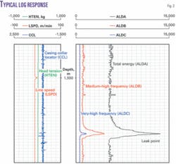
Fig. 2 shows a typical log presentation with three frequency windows of investigation. The three traces are: total energy level (ALD A), medium-high frequency (ALD B), and very-high frequency (ALD C). These ultrasound signal strength measurements do not have units.
For depth correlation, the log also includes a casing collar locator (CCL) track.
Reference 1 provides more details on the tool’s physics and development history.
Stationary readings at 1-2 ft increments above and below the leak can verify the exact leak location. With the tool positioned at the leak, manipulation of wellbore pressure can causes changes in the signal strength that can confirm which tubular has the leak.
North Slope history
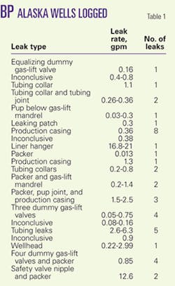
Since the introduction of the tool on the North Slope in December 2005, BP Alaska has logged 21 wells with an 81% success rate (Table 1).
Of these wells, 14 were producers and 7 were water or gas injectors. Liquid leak rates ranged from 0.013 to 21 gpm.
The logs have identified leaks in 10 annuli, 4 production casing strings, 4 packers, 1 wellhead, 1 liner hanger, and 1 tubing straddle. Nine wells had multiple leaks. One well had three leaks: tubing, packer, and production casing. Based on these results, 10 of these wells will have rigless repairs.
Dummy valve leak
The first ultrasonic log run by the operator in Alaska identified a leaking dummy gas-lift valve in an active water injection well.
The operator completed the well as a preproduced injector in 1983 and converted it to water-alternating-gas (WAG) injection in 1985. The completion included nine gas-lift mandrels with dummy valves.
The well injected miscible injectant (MI) gas during four cycles prior to developing tubing to annulus communication while injecting MI. Although the well passed a liquid pressure test of the annulus, the annulus pressure would increase during MI injection.
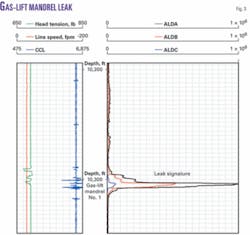
The logging operations for finding the leak involved placing the well on water injection at 4,900 b/d and 900 b/d with a 2,000-psi wellhead pressure. The annulus was bled off to 100 psi and then allowed to repressure while logging. Calculations based on pressure buildup indicated that the leak rate was 0.16 gpm. Fig. 3 shows the leak signature at the lowermost mandrel, which contained an equalizing dummy gas-lift valve. These valves are prone to leaks.
After replacement of the leaking valve with a dummy valve with extended packing stacks, the well successfully passed a pressure test.
This was the first time that the operator had identified a dummy valve as the source of tubing-to-annulus communication in an injector. Before the ultrasonic log, the general belief was that multiple thread leaks in the tubing caused slow tubing to annulus communication in WAG injectors.
Ultrasonic logs have identified three other injection wells with communication through eight leaking dummy valves. Replacement of the leaking valves repaired the communication. A new technique that uses nitrogen, discussed later in this article, detected the leaks in two of these wells.
At least 10 injectors in the operator’s Alaskan fields have had tubing replaced because of slow tubing-to-annulus communication. If ultrasonic logging had existed, the operator may have identified these as valve leaks and remediated them with rigless methods.
Memory tool
Running the tool in a memory mode on slick line is less costly and provides the operator additional flexibility. An added advantage of this mode is that it allows for a single rig-up to obtain a multifinger tubing caliper and leak-detection log.
If the log indicates a leak at a gas-lift mandrel, the slick line unit can immediately replace the dummy valve. If the leak is not at the mandrel, the slick line can run and set a dummy tubing patch in preparation for a wireline set tubing straddle. Of the seven memory jobs completed in Alaska, only one has been inconclusive.
One well was logged in real-time on wireline and in memory mode on slick line. Both wells had consistent log results, with no significant difference between the two methods.
The first memory ultrasonic log in the world was run in July 2006 in Alaska in Well 2, a water injector completed in 1991.
The well displayed communication with sustained pressure on the annulus. A multiarm caliper indicated that the tubing was in good condition, yet a leak was still present.
Because the leak was small, 1.1 gpm, the operator decided to run an ultrasonic leak-detection log. A tubing plug was set below the packer before logging. During logging, the leak rate was established by pressuring up and maintaining 1,500-2,200 psi on the annulus and bleeding off the tubing pressure to 500-700 psi. The leak rate ranged from 0.9 to 1.2 gpm.
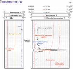
The log indicated a leak signature at a tubing connection (Fig. 4).
A memory temperature probe run in conjunction with the ultrasonic tool also showed a change in temperature at the leaking collar. The temperature probe detected other temperature fluctuations above the leak, however, while the ultrasonic tool showed no response. Often it is difficult to interpret temperature logs because of multiple temperature anomalies that may interfere in identifying small leaks.
Installation of a tubing patch is scheduled for Well 2.
Improper tubing makeup
The ultrasonic tool run on wireline identified a tubing leak in Well 3. After completion of the well with a new chrome string during a rig workover, the tubing failed a pressure test, leaking 0.2-0.8 gpm. The logging used a surface readout wireline while pumping down the annulus to maintain the leak.
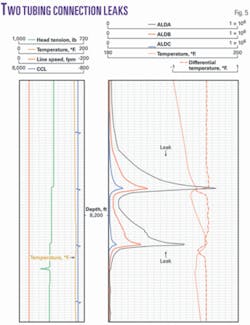
The log clearly showed leaks at the top and bottom connections of a tubing joint (Fig. 5). Note the more precise ultrasonic leak signature compared with the temperature traces.
An investigation concluded that the connections were improperly made up. After discussion with the service company, the field adopted an operating procedure to ensure the workover crew observed and recorded all aspects of the make-up (shoulder torque, number of turns, and final torque). The procedure also allows only three attempts for making up a tubing connection before the collar and joint are discarded.
Installation of a tubing straddle repaired the leaking connection, eliminating the 4 days and $1 million required for pulling and rerunning the tubing.
Casing leak
Detection of small casing leaks behind tubing is difficult, if not impossible, with conventional logging methods. Companies historically have tried with little success to identify small leaks by comparing a baseline temperature pass with traces logged after pumping into the annulus.
Well 4, a producer completed with 4.5-in. chrome tubing inside 9 5/8-in. casing, exhibited sustained annulus pressure and failed a pressure test.
The first step in determining the leak location was to test the tubing by installing a tubing tail plug and then applying pressure to test the tubing. Because the tubing held pressure, this suggested that the well had either a production-casing leak or a one-way packer leak.
The operator then ran the ultrasonic leak-detection tool in memory mode on slick line. The logging operation involved pressuring up the annulus and maintaining the pressure at 3,000 psi with a calculated leak rate of 0.36 gpm.
The log identified eight leaks, a tool record for the most casing leaks found behind tubing in one well. Temperature traces indicated minor fluctuations on the four uppermost leaks but did not indicate the lower four leaks.
Fig. 6 shows one of the leaks identified. Note that the temperature trace does not provide any conclusive information. Also note that casing leaks typically have a symmetrical shape. The other spikes below the leak signature exhibit a shape typically associated with mechanical noise.
Well 5
Well 5 had three types of leaks: tubing, packer, and production casing.
The operator secured Well 5 with a slick line plug after the well exhibited communication between the tubing-casing annulus, and the casing-casing annulus. A pressure test of the tubing-casing annulus failed with a leak rate of about 2.5 gpm. The tubing pressure tracked the annulus pressure during the test.
A pressure test of the tubing also failed, with a 0.48 gpm leak rate and the tubing-casing annulus pressure tracked the tubing pressure during this test.
A combination pressure test of the tubing and the tubing-casing annulus failed, indicating a possible packer or production casing leak. During this test, the tubing-casing and casing-casing annuli were in communication.
The evaluation of the tubing to annulus communication involved applying a pressure of 2,400-3,000 psi to the tubing and maximizing the differential pressure across the leak by taking returns from the tubing-casing annulus through a choke. The leak rate ranged from 1.2 to 2 gpm.
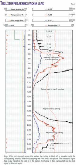
The leak was found to be at the packer and was confirmed by positioning the tool at the leak and manipulating the leak pressure and rate (Fig. 7).
The tool also located a shallow production casing leak in Well 5 that caused the tubing-casing and casing-casing annuli to be in communication. The second-phase logging operations involved pressuring up the tubing and tubing-casing annulus together to 3,000 psi to evaluate the production casing, packer, and casing-casing annulus. The test indicated a leak rate of 1.2-2 gpm.
The tool located the leak at 2,340 ft while pressuring the tubing and tubing-casing annulus together.
The leak was confirmed by positioning the tool at the leak point, equalizing the pressure, and observing the signal die away.
Wellhead leak
Well 6 exhibited slow tubing-casing and casing-casing annuli communication while on gas-lift. Multiple tests attempted to confirm whether the communication was in the wellhead past the intermediate casing hanger seals or from a shallow production casing leak. Diagnostics gave conflicting results and led to the running of the ultrasonic leak-detection log.
After obtaining a baseline pass, the test activated the leak by pressuring the tubing and tubing-casing annulus to 1,600 psi with lift gas. The leak rate fluctuated substantially, ranging from 0.2 to 3.0 gpm.
Lift-gas injection was halted while logging across the wellhead and tree to insure that any ultrasonic signal detected was due to leak activity.
A comparison of the two logs clearly indicates that the leak was in the wellhead. A pressure-activated sealant squeeze repair is planned to remediate the leakage past the wellhead seals.
Nitrogen use
The ultrasonic leak-detection tool in memory mode provides more opportunities to find smaller leaks. One advantage is that the tool can be run in high-pressure wells in which it is difficult to maintain a pressure seal for the wireline.
The technique developed by the operator uses nitrogen to identify leaks in WAG injection wells. These wells have typically 4,000-psi injection pressures. In some cases, injection wells can pass tubing-casing annulus pressure tests to liquid but build up pressure when injecting gas. These wells must remain on water injection until worked over to allow gas injection.
Many injection wells were previously producers and therefore have gas-lift mandrels. Miscible injectant gas consists of 35% methane, 20% each of ethane, propane, and carbon dioxide, and 5% butane. It is an excellent solvent and easily dissolves grease seals, o-rings, and elastomers.
To minimize logging risk in wells injecting miscible fluids, a technique was developed using nitrogen to simulate MI injection that requires only one slick line rig-up.
The procedure involves first performing a pressure test on the tree after which a multiarm caliper log run determines the tubing condition. Lift gas then depresses the well’s fluid level in the tubing as deep as possible. This step is not required but saves on the amount of nitrogen needed. Following this, nitrogen pumped into the well depresses the fluid level to below the packer.
Upon complete evacuation of the tubing, a tubing plug is set below the packer after which nitrogen is used to pressure the tubing to 4,000 psi. The ultrasonic tool obtains a baseline log after the tubing plug is run. After the tubing-casing annulus is bled to 0 psi, the tool logs the well to surface at 30 fpm, slowing to 10 fpm across any equipment placed in the tubing string.
BP Alaska has logged two wells with this technique. The first log found leaks at three gas-lift mandrels and the second log found leaks at four mandrels.
A subsequent change out of the dummy valves resulted in both wells passing 4,000-psi tubing-casing pressure tests. Subsequent MI injection will determine if the communication problem has been resolved.
Investigations also have addressed the possibility or replacing the dummy valve packing material with packing material that is more resistant to the miscible injectant.
Inconclusive logs
To date, BP Alaska has run four inconclusive ultrasonic logs. Two of these wells are scheduled to be relogged with increased differential pressure to ensure turbulent flow, possibly creating a stronger signal for identifying the leak.
Ultrasonic signatures depend on the rate, differential pressure, and leak geometry. A possible explanation of why a few logs were inconclusive is that one of these factors was insufficient for generating the expected result.
With small leaks, a leak may have gone silent when the tool passed. It is important to note that conventional methods cannot locate small leaks, particularly those behind tubing.
There have been a few problems in obtaining successful ultrasonic data. The most common, although infrequent, operational problem is the activation of small leaks that are either intermittent or one-way leaks. Patience is a requirement in assuring that any pressure fluctuations are leak behavior and not annulus ballooning or thermal effects. Pressure data analysis prior to the job serves to assist in avoiding this problem.
Because the tool almost always produces a very distinct signature, the logging operations may be streamlined further. Rather than taking time to confirm every leak under pressure manipulation, a complete pass may be made first, prior to investigating anomalies.
The number of leaks found and potential remediation techniques may help decide on whether to do additional logging.
Future plans
The number of rigless repairs in Alaska is expected to increase because this new technology can locate otherwise unidentifiable leaks. Millions of dollars have already been saved in the last year.
The method is preferred over conventional leak-detection logging tools because of its sharp leak delineation. The tool, however, has not been used to detect leaks greater than 2 bbl/min. Rates greater than this may be a tool limitation.
The track record has proved that ultrasonic technology is a viable, efficient, and economic option in detecting leaks as small as 0.0024 gpm. The tool has become part of the standard well work toolkit in Alaska.
The tool’s pinpoint accuracy is superior to conventional leak-detection methods, and continued work is ongoing to determine if the tool can detect ever smaller, as well as larger, leaks.
Further ultrasonic-based tool development underway includes a high-temperature leak-detection tool. In addition, a tool for detecting microannulus flow, and a tool which will illustrate the flow profile at the produced interval have been released and now are in field use.
Acknowledgments
The authors thank the management of BP Exploration Alaska and other unit working interest owners for permission to publish this article. The opinions stated and the techniques described are those of the authors and are not necessarily shared by Unit Working Interest Owners.
Reference
- Johns, J.E., et al., “Applied Ultrasonic Technology in Wellbore Leak Detection and Case Histories in Alaska North Slope Wells,” Paper No. SPE-102815, SPE ATCE, San Antonio, Sept. 24-27, 2006.
The authors
Jennifer Julian ([email protected]) is a senior well work design engineer at BP Exploration, Alaska. Previously she worked for Arco as a well site supervisor, production and injection engineer, and a log analyst . Julian holds a BS in petroleum engineering from the New Mexico Institute of Mining and Technology. She is a member of SPE and ICoTA.
George King is a distinguished advisor for BP. Previously he worked for Amoco. King’s work has involved oil and gas well completions, stimulations, workovers, and operations. He currently is involved in mentoring, teaching, field reviews, innovation issues, problem well analysis, intervention designs, and general consulting in production engineering. King has a BS in chemistry from Oklahoma State University, and a BS in chemical engineering and an MS in Petroleum Engineering from the University of Tulsa. He is an SPE member.
Daniel B. Robertson (robertdb @bp.com) is a senior petroleum engineer with BP Exploration, Alaska. He has worked for BP in various supervisory and engineering positions in Alaska. Robertson holds a BS in both petroleum and mechanical engineering from the University of Alaska, Fairbanks. He is a Registered Petroleum Engineer in Alaska and is a member of SPE and ASME.
Joel Johns ([email protected]) is the US sales and marketing manger for TecWel AS. His experience is in manufacturing, design, and marketing of oil field equipment and services. Johns holds a BS in electrical engineering technology from Louisiana Tech University. He is member of SPE and ICoTA.
Janet Sack ([email protected]) is a well intervention engineer for BP Exploration, Alaska. She specialized in well work intervention including slickline, wireline, and coiled tubing. Sack holds a BS in civil engineering from Gonzaga University. She is an SPE member.


