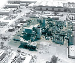
World’s largest LNG compressors designed, tested for Qatargas II
Growing global demand for LNG has spurred an increase in LNG liquefaction capacity. An example is Qatargas II, a joint venture initiated by Qatar Petroleum and ExxonMobil for a two-train expansion (Trains 4 and 5). Ownership of Qatargas II has recently expanded to include Total (for Train 5). The project will employ the world’s largest LNG refrigeration strings, while also reducing plant emissions and making efficient use of energy sources.
The project has applied APCI’s AP-X process for two large LNG trains (7.8 million tonnes/year; tpy) under construction in Qatar at Ras Laffan Industrial City (RLIC). About 280 Mw of refrigeration compression will be required to achieve this goal.
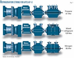
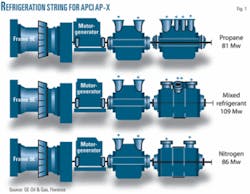
The economy of scale incentives highlighted the GE Frame 9E as the ideal mechanical driver for the refrigeration strings (Fig. 1). An extensive qualification effort was required to adapt the GE Frame 9E power-generation gas turbine for variable-speed mechanical drive service. System reliability was improved through a design program that targeted reduction of the number of components.
In addition, considerable effort concentrated on reducing plant emissions through qualification and use of dry low NOx (DLN) burner technology suitable for the low-btu, LNG mechanical drive application.
Further improvements to efficiency required a solution to the impact of diurnal and seasonal ambient temperature variations on the gas turbine’s power output. Development of a unique, variable-speed, electric motor-generator met this requirement. The motor-generator enables pressurized starting of the compressors, ensures adequate power for refrigeration compression, and exports surplus power as electricity into the plant grid to utilize the full capability of the gas turbine.
This article also discusses the design, manufacture, and full-load string testing for the six main refrigeration compressor casings. ExxonMobil and GE proprietary qualification processes managed the technical risks associated with this string design.
Experience called for development of single-piece manufactured impellers. Extensive use of computational flow dynamics simulation and modeling authenticated the aerodynamic design. Finally, advanced sealing technology was developed for refrigerant sealing at very large shaft diameters.
Frame 9E gas turbine
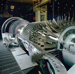
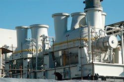
Speed, fuel, and emissions studies qualified the Frame 9E gas turbine (Fig. 2).
The GEMS9001E (Frame 9E) gas turbine has an extensive operating history since 1978 in power generation. ExxonMobil initially qualified the Frame 9E for mechanical drive LNG service based on 100% constant speed and fuel gas with 38% nitrogen content.
GE then performed a study to customize the Frame 9E for variable-speed operation without compromising maintenance intervals or life expectancies. The speed study assumptions were:
- Operating ambient temperature: 4° C. to 49° C.
- Five to 30 starts/year (mature design at 5/year).
With these assumptions, assessment of the following components verified life expectancy over a speed range of 2,850 rpm (95% speed) to 3,150 rpm (105% speed):
- Axial compressor rotating and stationary blades.
- Turbine rotor and buckets.
- Gas dynamics in combustion cans and transition pieces.
- Gas flow disturbances in the combustion system, exhaust diffuser, and collector.
Gas turbine components are subject to such failure mechanisms as low-cycle fatigue crack initiation, cycling-crack propagation, disc burst, and creep. All of these failure modes were evaluated at baseline conditions and at 105% speed.
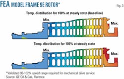
A finite-element analysis model based on parameters that defined the thermodynamic behavior of the unit (power output, pressure ratio, mass flow, speed ramps, etc.) calculated temperature distribution, aeromechanical loads, inertia loads, etc.
Another part of the study evaluated the Frame 9E compressor airfoil rotor and stator blades ability to operate in the 95% to 105% speed range. The conclusion was that stresses remained within allowable limits (Fig. 3).
Torque ripple effect contributions from the VFDs were also assessed and considered a low risk to the compressor blades. This analysis, coupled with the operating experience of the Frame 9E compressor rotor, confirmed that the Frame 9E could operate continuously as a mechanical drive in the speed range of 96% to 102 %.
Hot gas path components were analyzed for aeromechanical (modal) creep and life-cycle-fatigue capability. Modal analysis revealed that resonance is avoided between bucket natural frequencies and high-strength drivers at rotor speeds between 95% and 105% speed. Creep resistance of the rotor was evaluated against the 200,000-hr limit for Frame 9E gas turbines. The turbine rotor dovetails exhibited sufficient margin to operate at 49° C. at continuous speed up to 105%.
Finally, FEA modeling to identify and quantify life-cycle-fatigue rotor components life analyzed the effect of variable speed up to 105% operating at 49° C. ambient temperatures. The life requirements were set at 300 starts over the life of the rotor for this application (10 starts/year, 30 years’ operation). Results showed the components have margins beyond the conservative 300-starts requirement.
The study concluded a speed range 96% to 102% was suitable for continuous operation and transient excursions up to 105%.
In addition, the Frame 9E is equipped with a dry low NOx combustion system for emission abatement (DLN-1). In a normal application this system is capable of 25 ppm (vol, dry; ppmvd) of NOx and requires a variation of no more than ±5% from a given Wobbe Index (WI) target value for the fuel gas.
(WI is the ratio between the fuel’s lower heating value (LHV) and the square root of specific gravity multiplied by fuel temperature. This can be thought of as a measure of the energy density of the fuel.)
QGII fuel gas is supplied by the LNG process and supplemented during various modes of operation. The fuel gas may have a WI variation as high as ±26%. The WI range and rate of change is limited to ensure adequate pressure ratios across the fuel nozzles. If the pressure ratio is too low, the combustion dynamics amplitudes can increase to unacceptable levels leading to shortened operating life and poor reliability.
Combustion testing was performed to verify the combustion hardware was capable of handling fuel gases ranging 4% to 48% N2. Additional lab tests verified that the selected fuel nozzles and combustion chamber design stayed within acceptable performance limits.
NOx emissions decrease as the N2/CH4 ratio in the fuel gas increases. While this effect is beneficial for reducing emissions, it can reduce the reliability of the combustion system. Extremely low NOx emission values for this combustion system can indicate a weak flame, which in turn could lead to a combustion blowout or high combustion dynamics.
To compensate for the high N2 fuel content, the dilution area of the liners was increased to achieve a robust flame over all operating conditions.
This liner modification, coupled with the redesigned fuel nozzles, produced test results that showed the combustion system can operate throughout the required QGII range. The NOx is expected to be less than 25 ppmvd while running on fuel gases with 25% to 42% nitrogen.
Complementary to the combustion design changes was the addition of GE’s Extendor technology maximizing availability.
Motor-generator; VFD system
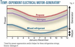
The design basis of the motor-generator, variable-frequency drive system manufactured by Siemens was to support flat LNG production by providing sufficient string torque under all ambient conditions (Fig. 4). The design and operability of the string were validated during back-to-back and string testing.
The synchronous motor-generator manufactured by Ansaldo Sistemi Industriali SPA incorporates integral shaft flanges that mechanically connect the Frame 9E and the centrifugal compressors. This design is based on a theoretical limit that allows the turbine to transfer full power to the compressors at the same time the motor-generator also supplies full power (45 Mw, 143 kN/m base, 60 Mw, 190 kN/m peak) to the compressors.
The VFDs are designed not only to support a base full motor power (45 Mw, 143 KNm) in either generation or helper motor modes. They are also designed to provide peak power up to 190 KNm of motor starting torque (corresponding to 60-Mw@3,000 rpm) for 90 sec. This enables pressurized starting of each string, reducing starting time as well as emissions.
Parallel operation, redundancy
High availability flat LNG production required a 60-Mw system design. Since the VFD technology selected was limited to 15 Mw/drive (“threads”), four drives were required for each compression string.
The 15-Mw limit, however, provided an opportunity for system redundancy. Each motor is normally fed from four VFDs with each VFD feeding a separate motor-generator stator winding. The design using four parallel drives, not only supports the 60-Mw requirement for pressurized starts, but can also operate continuously at 45-Mw in motor-generator mode with only three VFDs.
To provide a double level of redundancy, the VFDs are designed so that a single VFD can provide full power (15 Mw) with one of the power cells out of service in each phase (total three cells out on different phases) or two power cells out in any one phase. It is also important to note that only two VFDs are required to permit depressurized starting, flat LNG production, and turning-gear operation.
Even the simultaneous trip of all four VFDs does not necessarily imply a string trip interrupting LNG production. With the VFDs tripped, the motor simply acts as a coupling between the turbine and the compressors. Once the VFDs are available, they can be restarted without requiring shutdown of the Frame 9E.
Turning gear function
The VFDs and motor-generator were developed to provide the string’s turning gear function. This replaces the standard accessory base functions of breakaway torque, slow roll turning, purge, starting, water wash, and cool down. A dedicated emergency low-power circuit has been incorporated into the design to permit 300-rpm turning gear operation in the event of a plant blackout.
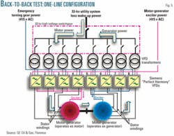
Back to back testing was performed at the ASI facility in Monfalcone, Italy, to validate system design and compare its performance with predicted and guaranteed values. The back-to-back configuration consists of mechanically coupling two motors with each motor fed by four 15-Mw VFDs (Fig. 5).
During this testing, one of the units was operated as a motor simulating the turbine by providing positive torque. The second unit was operated as a generator, converting mechanical energy from the first unit to electric power. This configuration required that the utility supply only enough electric power to cover system losses.
Back-to-back testing confirmed system performance not only met guaranteed values but also exceeded the less conservative predicted values. For example, the motor-generator had to operate below a Class F temperature rise at full load (45 Mw) with only three VFDs (i.e., one “failed” VFD). Back-to-back testing, however, determined actual temperature rise was well below this value and in fact below a Class B temperature rise.
Compression power generation
Each VFD is provided with an active front end (AFE) capable of supplying real power or reactive power to the plant grid, whenever excess turbine power is available. Reactive power is also controlled by the AFE by adjustments to the voltage to control the export of reactive power to the plant grid.
Since VFDs isolate the motor-generator from the plant grid by converting plant power from 50-cycle AC to DC and then to a variable AC, power flows between the plant grid and the motor-generator are independent of motor-generator shaft speed.
Each compression string is capable of supplying up to 45 Mw of real power, depending on excess turbine torque availability, and 30 Mv amp (reactive) power to the plant electrical grid continuously at variable speed.
Pressurized starting
On most gas turbine mechanical-drive applications, the centrifugal compressor load (function of process loop pressure) at string start-up usually is maintained as low as possible. The compressors are then loaded once the turbine reaches the minimum continuous speed.
The same concept is applied to generator drive units (normally single-shaft units), in which the gas turbine reaches full speed in an unloaded condition. This allows reduction in the size of the starting devices and reduces loading of the gas turbine axial compressor during the start-up transient phase.
In an LNG plant this depressurized starting method results in:
- Loss of refrigerant to depressurize refrigeration loops after any plant shutdown.
- Flaring.
- Increased plant downtime (about 8 hr required to complete plant start-up).
As a consequence, pressurized starting capability can help to increase plant availability by greatly reducing starting times, while at the same time reducing plant flaring and associated emissions. The incentives of pressurized starting capabilities led to a major development effort.
An initial feasibility study formed the basis for starter motor sizing. Since the required start-up torque is a function of compressor load-loop pressure and rotating inertia, it was critical fully to understand fully the complete compression system as well as the Frame 9E and motor.
A rigorous dynamic simulation took into account the Frame 9E transients, using a GE proprietary model based on Frame 9E actual control software and cycle deck performances. The simulation included the electric motor-supplied torque, compressor load, and train inertias. Pressurized starting was considered feasible with a 45-Mw motor with 60-Mw peak load capability.
Dynamic simulations performed by GE using site conditions showed the need for extra-torque from the Frame 9E for speeds greater than 82% for N2 and C3 and above 70% speed for the mixed-refrigerant train.
Additional starting torque was obtained by modifying the standard turbine generator drive’s start-up sequence, increasing fuel flow rate, and anticipating the turbine-inlet guide vane opening. This resulted in a dedicated augmented start-capability test campaign designed to explore higher Frame 9E axial pressure ratios.
A nonstandard development engine approach explored the new operating line limit. In order to take into account engine deterioration with accumulated operating hours and engine-to-engine variation, a 10% margin in terms of pressure ratio was necessary to validate the final operating line limit. This margin forced a higher level of pressure ratios during the test campaign.
In summary, achieving initial project objective of pressurized starting at nearly all site conditions not only simplifies starting and greatly improving plant availability, but also minimizes plant emissions.
Centrifugal compressors
From early stages, GE and ExxonMobil shared centrifugal compressor design development. ExxonMobil performed technical reviews covering many aspects of the compressor design.
QGII compressors are the largest centrifugal compressors designed by GE for LNG applications (Fig. 6). Although the compressor architecture is not completely new, GE introduced several innovations to mitigate risks associated with manufacturability and performance of these compressors.
The process compressors are in two bodies on each string. The inboard compressor connected to the motor-generator is a drive-through horizontally split casing (MCL type). The outboard compressor is either an MCL type or a barrel type (BCL), depending on the pressure rating. Positioning the barrel compressor outboard in the string reduces time required to remove the inner barrel assembly axially.
The large, horizontally split compressors were designed for ease of maintenance by the upper half diaphragm being separated from the upper half casing to reduce the heaviest maintenance lift and avoid the need to rotate the upper half casing to service upper half diaphragms. Removal of the upper half casing leaves the upper half diaphragm in place. The diaphragms are then removed to reveal the rotor.
These barrel compressors are the largest ever built by GE, with a maximum weight of 115 tons.
Single-piece impellers
The QGII compressors are equipped with three-dimensional impellers machined from a solid forging. Each impeller is machined with a five-axis milling machine, eliminating the need for welding.
This manufacturing process provided excellent control of the blade geometry without reducing tensile properties associated with weld joints. This technology also increased steel alloy options without the constraints of material weldability.
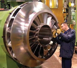
A computerized measuring device then checked each impeller to assess the possible impact of geometrical deviations. The single-piece impeller method guarantees repeatability and improves performance (Fig. 7).
QGII compressors were designed to optimize both rotordynamics and aerodynamic performance. In particular, propane compressors are often limited by an impeller-eye Mach number resulting in premature choking of the stage.
Splitting the propane compressor into two bodies allowed the high-pressure section to have a smaller shaft. This solution reduced the impeller-eye Mach number, avoiding premature choke.
All barrel compressors completed aerodynamic performance testing in Florence, Italy. Their large size forced the horizontally split compressors to be aerodynamically tested while in the string configuration in Massa, Italy. Barrel compressor performance was revalidated during the string tests to ensure consistency of testing results between sites. The results showed better than expected efficiencies. A broad operating range was demonstrated between surge and overload.
Massa string test
As final validation before shipping, GE performed a full-power string test on each of the three compressor strings at GE’s Massa facility (Fig. 8). These tests were to replicate as much as possible the plant site configuration.
The tests used the contract Frame 9E gas turbine, compressors, motor-generator, and associated VFDs. Also included were such subcomponents as inlet-air filtration system, inlet-bleed heating, oil system, and the dry-gas sealing system. The only difference with the site configuration was the use of a temporary on-base Frame 9E enclosure instead of the contract off-base enclosure.
A large portion of the string testing involved final validation of the VFD system and its integration with the main equipment as well as with the power supply grid. Engineering Dynamics Inc. used an advanced recording system closely to monitor shaft torque ripple (a well-known weak point of variable-frequency systems) and the amount of harmonic disturbances injected by the system into the surrounding electrical grid. Results validated low torque ripple, well within the design basis, therefore requiring no external suppression.
Testing achievements
Flow measurement at each bearing inlet as well as bearing temperatures throughout various operating conditions fully validated the oil system.
Massa testing simulated loss of complete AC power under full load. The emergency oil pump and overhead rundown tank provided adequate oil to protect the string during coast and cool down. The system also demonstrated the capability to maintain minimum lube-oil pressure with only one of the 3x100% AC pumps running.
Functional testing of the dry-gas-seal system validated the requirement to support the seals during all operating conditions. This included the ability to supply buffer gas during compressor settle out conditions through use of an on-board booster compressor, eliminating the need for external buffer gas that can often contaminate the compressor refrigeration loops, which can lead to additional delays in train restart and flaring.
The load test was the final validation of the train alignment procedure (especially for the rigid shaft line Frame 9E + motor-generator supported by five bearings). In addition to the contract string bearing’s vibration-monitoring system, an extensive temporary vibration-monitoring system was installed on the piping, casings, bearing pedestals, and support structure. This provided a complete picture of the string rotor dynamics. All measurements were well within specified limits, validating lateral analysis studies.
The Frame 9E is equipped with DLN-1 NOx combustion system and IBH to improve system operability. The DLN-1 system allows very low NOx emissions, provided that all combustion control parameters are properly adjusted to take into account site conditions and unit-to-unit variations.
DLN-1 system tuning is normally performed at the site as one of the commissioning activities. In this case, a pretuning was performed in Massa to demonstrate the system’s capability in terms of operability and emissions. This has the additional benefit of reducing the site-commissioning schedule. Measured NOx emissions were well within the 25-ppmvd target over a wide load range.
The commissioning sequence of the main equipment started with the motor solo run in which the electric motor is disconnected from the Frame 9E and from the compressors. For this operation, a temporary thrust bearing was added to the motor shaft.
The motor was then connected to the Frame 9E to perform the turbine solo runs. Finally the string was coupled and full load testing was initiated, validating the ability of the VFD motor to perform all string starting and cool down functions.
This validated the early decision to utilize the VFD motor in lieu of the standard Frame 9E accessory gearbox, thus improving string reliability by reducing the number of system components.
The Frame 9E’s response at low power, combined with peaking mode, will be used in the field to avoid tripping of the MR string during loss of VFD when in helper mode.
Additional tests validated VFD double level of redundancy, in particular the capability to supply uninterrupted power (45 Mw) with one cell failed in one thread and a second one in a second drive, as well as with a complete thread (VFD) out of service.
The first turbines started shipping to RasLaffan in 2006. Installation took place throughout 2006-07.
Operation is to commence in 2008
The authors
Roy Salisbury ([email protected]) is a senior associate working for ExxonMobil’s Upstream Development Co., Houston, and currently assigned to Qatargas II Onshore Project as the lead machinery engineer. He has previously worked as field service manager for both Elliott Co. and Siemens Demag Delaval Turbomachinery. In addition, he held the position of shop operations manager of Elliott’s Service facility in Houston. He is a graduate of the University of Pittsburgh.
Pete Rasmussen ([email protected]) is the chief machinery engineer for ExxonMobil’s upstream companies. Over the past 29 years he has held various positions in ExxonMobil upstream organizations working machinery solutions and reliability issues. He currently leads machinery research efforts at the ExxonMobil Upstream Research Co. Rasmussen holds a BS (1974) in ocean engineering from Florida Atlantic University and is a licensed professional engineer in Texas.
Todd Griffith ([email protected]) is an engineering specialist, currently leading the machinery group at ExxonMobil Upstream Research Co. He previously was a project engineer seconded into Qatargas II during the onshore facility design development. He has 6 years of related industry experience. Griffith holds BS and MS degrees in mechanical engineering from Texas A&M University.
Andrea Fibbi ([email protected]) is currently manager-auxiliary and systems engineering team for GE Oil & Gas, Florence, Italy. He previously served as Qatargas II project leader for GE Oil & Gas during project development and validation phases. He has 13 years of experience in turbomachinery systems design and system integration and holds a degree in mechanical engineering from the University of Florence (Italy).
