Study evaluates how to improve rod pumping in mature field
A study of a mature onshore field with more than 70 rod-pumped wells found several ways for improving pumping operations.
The profitability of rod pumping is a direct function of the energy requirements. For higher profits, the operator needs to maximize pumping-system efficiency. This requires finding the optimum pumping mode for the desired liquid production rate.
The study included an extensive measurement program involving more than 50% of the wells. A portable computerized system obtained the pumping parameters, and a detailed evaluation of measurement data facilitated the detection of general and specific problems in the design and operation of the pumping installations.
With the aim of improving the field-wide profitability of pumping operations, the study optimized each well’s pumping parameters. Calculations showed that the operator could anticipate about a 17% field-wide power saving if all wells operate at their most economic pumping mode.
Study objective
The study had three different, but interrelated tasks:
- Assess the current operating conditions of producing wells and find problems.
- Determine the optimum pumping mode for each well while keeping current equipment and liquid production rate restrictions.
- For selected key wells, take into account available inflow performance information to determine and verify optimum pumping system design to ensure the greatest liquid production increase by reaching pumped-off conditions.
Based on these findings, the study recommended ways to avoid problems and suggested specific ways to improve operational conditions.
The pumping mode optimization had the following restrictions:
- Liquid rates were kept at current levels.
- Main installation parameters, such as pump setting depth and tubing size, were not changed.
This evaluation allowed the operator to see the benefits of selecting the optimum pumping mode for each well. The most important improvement was the reduction of the power requirements. The study determined this for each well and for the entire field with and without tubing anchors in the wells. The current practice in the field is not to have tubing anchors.
The final study objective investigated the possibility and the effects of increased liquid production rates. This involved selecting several key wells for determining the maximum pumping rates obtainable.
For these wells, the study properly loaded and obtained sufficiently high power efficiencies for the surface systems such as pumping units and gearboxes, in contrast to current well conditions.
Measurement procedure
The study obtained measurements on the pumping wells with a portable computerized system, including the required hardware and software components, that was specifically developed for testing and analyzing sucker-rod pumped oil wells.
A complete analysis of a rod-pumped installation with the portable equipment involves several phases and requires the adherence to specific procedures. Each phase can be conducted independently but proper and complete well analysis usually has the following steps:
- Without stopping the operation of the pumping unit, find the dynamic liquid level in the annulus with an acoustic device.
- After the casing valve is closed, measure the pressure buildup vs. time at the casinghead to determine the well’s gas production rate.
- Conduct a dynamometer survey to measure the polished-rod loads and movements for several pumping cycles. It is important to record a representative, stabilized surface dynamometer card for further analysis.
- Test the downhole pump traveling valve and standing valve.
- Measure the electric power used to establish the electrical parameters of the motor’s input power.
Measured data evaluation
The study processed most measured data online with a portable analyzer system at the wellsite and stored appropriate parameters and diagrams in computer files. In addition to the factors calculated by the software, the study evaluated other operational parameters for each well. The following describes the parameters not readily available and those requiring additional explanation.
The study based well inflow calculations on the dynamic fluid level. After calculating the FBHP (flowing bottomhole pressure), the study had two options available for finding the well’s inflow performance:
- Use the constant PI (productivity index) principle.
- Use the Vogel IPR (inflow performance relationship) curve.
For the majority of the cases, the study used the PI principle because no free gas entered the wells from the perforations.
Other parameters included:
- Surface system loadings expressed as percentages of equipment ratings.
- Beam loading calculated as the ratio of the measured PPRL (peak polished-rod load) to the pumping unit’s structural load rating.
- Gearbox loading determined from the ratio of the measured peak net torque and the torque capacity of the gearbox.
- Motor load expressed by the ratio of the rms (root mean square) current taken by the electric motor to the motor’s full-load current rating.
- Rod loading of the individual tapered portions of the string expressed as the percentage of the maximum allowed rod stress. The allowed stresses were calculated from the modified Goodman diagram, which is used for evaluating the fatigue loading of sucker-rod strings.
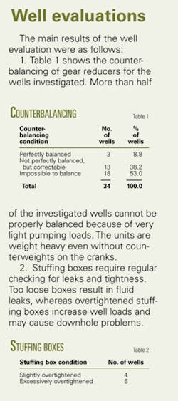
The analysis program calculates the degree of counterbalancing of the gearbox and recommends ways for achieving optimum conditions. This may involve moving or replacing counterweights on the unit’s cranks.
The results of the valve tests as well as the shape and other parameters of the calculated pump cards determined the downhole pump conditions. In some cases, usually for wells with older production tests, the calculated pump displacement varied substantially from the latest measured liquid rate. In such cases, to verify the measurement accuracy, the study calculated the pumping rate with the API RP11L model.1
If the calculated liquid rate did not agree with the analysis program output, the study did not use the production test data and recommended a new test.
Various publications define and calculate power efficiency of sucker-rod pumped installations in different ways.2-4 This study defines power efficiency, in general, as the ratio of useful and total input power to a system.
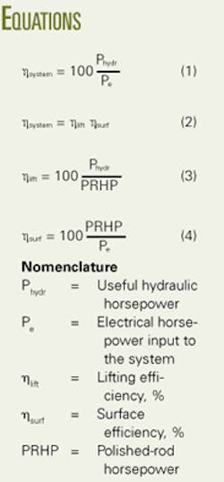
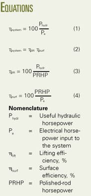
The useful power for the rod-pumping system is calculated from the amount of liquid lifted and the lifting depth, while the total electrical energy input to the system is measured with the portable analyzer. Thus, Equation 1 (see equation box) yields total system efficiency.
The system’s total efficiency equals the efficiencies of the downhole system added to the efficiency of the surface drive train. The latter includes the pumping unit, gearbox, V-belt drive, and electric motor. With the efficiencies to those two components assigned, Equation 2 will express the system efficiency. Lifting efficiency represents the efficiency of energy used and the losses in the downhole system, which includes the downhole pump and the rod string. Its value depends on the proper selection by the production engineer of the pumping mode, which includes pump size, polished-rod stroke length, and pumping speed.
Equation 3 calculates the lifting efficiency from the measured polished-rod power (PRHP).
The surface efficiency, calculated with Equation 4, includes all energy losses in the drive train.
A comparison of the efficiencies facilitates the detection of problems in a given rod-pumped installation.
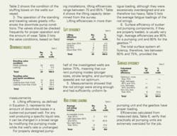
The accompanying box shows the main results from the evaluation of the wells in the mature field.
Artificial design
Artificial lift design aims to ensure the most economic means of liquid production within the constraints imposed for the given well and reservoir. For rod pumping, this means selecting the right size of pumping unit and gear reducer, as well as determining the pumping mode.
A designer only can select the pumping unit and gear reducer size if the operating conditions, such as loads and torques, are known. These conditions vary for different pumping modes. The basic task of a proper design, therefore, lies in determining the optimal pumping mode.
Optimum pumping mode is the combination of pump size, polished-rod stroke length, pumping speed, and rod-string design that results in the maximum lifting efficiency (Equation 3).6 7 This coincides with the case of setting the polished rod horsepower (PRHP) to a minimum because lifting efficiency and PRHP are inversely proportional for lifting a given liquid volume from a given pump setting depth.
The pumping mode determined with the previously described principle needs the least amount of prime-mover power because the system’s total energy requirement is a direct function of PRHP. Application of this optimization concept, therefore, gives the most energy-efficient and thus most economic pumping mode for producing the desired liquid rate from the given pump setting depth.
As also shown by Gault,8 a pumping system design using this principle results in minimum operational costs and in maximum system efficiency.
In rod pumping, power costs for driving the prime mover are a large part of operating costs. Thus the importance of selecting the proper pumping mode that meets minimum energy requirements cannot be overestimated.
The optimization procedure, as discussed, finds the least amount of power required at the polished rod. Because total energy use of the pumping system is directly related to polished-rod horsepower (PRHP), the optimization model automatically finds the most energy-efficient pumping system.
Optimization strategy
The study optimization evaluation included the following restrictions:
- Maintain liquid production rates as reported in the latest production tests, if reliable.
- Use present surface equipment such as pumping unit and prime mover.
- Use the current rod-string composition (API Rod Code).
- Do not change pump setting depths.
- Use dynamic fluid levels as measured.
- Use water cut from the latest production test.
The two cases studied included one with and one without a tubing anchor in the wells. The optimization process involved not only the optimum pumping mode parameters but also required the design of the rod string.
Calculated results
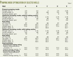
Table 1 shows the results of the pumping mode optimization for some of the wells investigated. The table lists the optimum pumping modes along with the required rod-string designs. It also includes for each well the following parameters related to the power efficiency of the pumping system:
- Increase in lifting efficiency, related to the current value.
- Decrease of energy requirements related to the current energy consumption.
The average energy savings per well for the 30 valid cases in this study is 16.4% for unanchored and 18.3% for anchored tubing strings. The operator can expect a field-wide power saving of about 17% if all wells are converted to their most economic pumping modes.
Optimizing key wells
The study also investigated the potential for increasing the liquid production rates of several key wells in which the higher rate was expected to have a limited effect on the well’s water cut.
This optimization involved determination of the maximum possible liquid rates as well as the selection of the optimum pumping modes that would ensure those rates. All predictions used the following assumptions:
- Because wells already have the largest possible tubing size for the casing sizes, tubing size was not included in the optimization.
- Existing pumping units on the wells were used in the optimization.
Calculation procedure
Rod-pumped wells produce at a maximum liquid production when the subsurface pump operates near to a pumped-off condition. This condition means that the dynamic liquid level should be at the pump’s setting depth.
It follows that the rod-pumping system has its maximum liquid production capacity when the pump is set at a depth just above the well’s perforations. The study, therefore, recommends setting the pump depths for the key wells at a few hundred feet above the perforations.
The first step in optimizing the key wells determined the maximum possible liquid rate, qlmax, from the well using the PI and the calculated FBHP.
Assuming the existing pumping unit with its capacity restrictions, the next step calculated the maximum liquid production capacity, q*max, of the pumping installation. When determining this rate, it considered the following parameters:
- A pump size compatible with the well’s tubing size.
- Availability of polished-rod stroke lengths and pumping speeds on the given pumping unit.
- Pumped-off well conditions.
The optimization process considered all possible combinations of these parameters and designed rod strings for each individual case. The results only kept the cases meeting the following criteria:
- Rod strings not overloaded, considering the fatigue endurance limits of Grade D rods.
- Gearbox not loaded above the torque rating of the given pumping unit.
- Peak polished-rod load (PPRL) less than the pumping unit’s polished-rod capacity.
At this point, the optimization process compared the two liquid rates qlmax, the well’s capacity, and q*max, the pump installation’s capacity and, obviously, selected the smaller of the two for all subsequent optimization calculations.
The next step in the process determined the optimum pumping mode to obtain the desired production rate. This involved selection of pump size, polished-rod stroke length, and pumping speed combination that ensured maximum lifting efficiency. As in the previous calculation, this calculation assumes a perfectly balanced pumping unit.
Optimization results
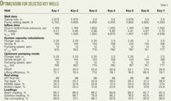
For some sample wells, Table 2 shows basic well data, results of the inflow calculations, and system capacity calculations. It also lists parameters of the optimum pumping mode along with detailed design of rod string and loadings of main system components.
This study provided the following conclusions.
- Practically all of the determined optimum pumping modes have lifting efficiencies in the 70% to 85% range.
- The fatigue loading of the top tapers in the rod strings is sufficiently high to ensure proper utilization of the rod’s strength.
- All of the beam loads, compared to the unit’s polished-rod capacity, are greater than 60%, an indication of a proper design.
- Gearboxes are loaded fully to ensure a high torque efficiency of the pumping unit.
It must be emphasized that, contrary to current operating conditions, the sucker-rod pumping installations designed for the key wells are loaded properly.
Because of proper loading of gearbox and pumping unit, one can expect surface system efficiencies in the optimum range between 60% and 75%. By comparison, all wells included in the field measurement phase of this project fell below the 60% efficiency range.
References
- Recommended Practice for Design Calculations for Sucker-Rod Pumping Systems (Conventional Units), API RP11L 4th Edition, Washington DC, 1988.
- Lea, J.F., and Minissale, J.D., “Beam Pumps Surpass ESP Efficiency,” OGJ, May 18, 1992, p. 72.
- Lea, J.F., Rowlan, L., McCoy, J., “Artificial Lift Power Efficiency.” 46th Southwestern Petroleum Short Course, Lubbock, Tex., Apr. 21-22, 1999.
- Takacs, G., “Power Efficiency of Sucker-Rod Pumping Systems” 50th Southwestern Petroleum Short Course, Lubbock, Tex., Apr. 17-20, 2003.
- Kilgore, J.J., Tripp, H.A., and Hunt, C.L., “Walking Beam Pumping Unit System Efficiency Measurements,” Paper No. SPE 22788, SPE ATCE, Dallas, Oct. 6-9, 1991.
- Takacs, G., Sucker-Rod Pumping Manual, Tulsa: PennWell Corp., 2002.
- Takacs, G., “Program Optimizes Sucker-Rod Pumping Mode,” OGJ, Oct. 1, 1990, p. 84.
- Gault, R.H., “Designing a Sucker-Rod Pumping System for Maximum Efficiency,” SPE Production Engineering, November 1987, pp. 284-90.
The author
Gabor Takacs ([email protected]) is a professor and head of the petroleum engineering department at the University of Miskolc, Hungary. His experience includes more than 30 years of teaching and consulting in production engineering. He was a visiting professor at Texas Tech University during 1988-89 and at the Mining University of Leoben, Austria, in 1995. Takacs holds an MS and PhD in petroleum engineering from the University of Miskolc.
