REFINERY REVAMP-1: ConocoPhillips revamps crude unit to increase flexibility, profitability
The ConocoPhillips refinery in Ponca City, Okla., recently completed a project to increase refinery profitability through increased flexibility of its No. 1 crude and vacuum unit. The revamp, which focused primarily on improvements to the vacuum distillation section, enabled the refinery to improve significantly its net operating margin by increasing the unit’s capability to process a high percentage of price-advantaged crudes.
Process flexibility is a key component in maximizing refinery profits. Changing petroleum markets provide opportunities to improve net operating margin if the refinery has the capability to capitalize on price-advantaged crude stocks and a market-driven product slate. For most refineries, this type of flexibility starts in the crude unit.
Crude unit revamps, however, can be cost prohibitive if the engineering design does not fully consider the practical aspects of modifying an existing unit.
This article, the first part of two, discusses the project’s front-end processing, vacuum tower design, and vacuum heater design. The conclusion, next week, will further focus on crude preheat train modifications, then discuss the overhead vacuum system design, construction and turnaround planning, and processing results due to the revamp.
The design features of this project illustrate some keys to developing a robust and flexible crude unit revamp. Successful implementation required working with existing equipment limitations and layout constraints, and maximizing overall constructability while minimizing construction downtime.
The results of the Ponca City revamp have met or exceeded the design performance expectations and positioned the refinery for even greater profitability once other refinery limits, exposed only as a result of this revamp, are addressed.
Background
In late 2001, ConocoPhillips initiated a project in its Ponca City refinery to increase the processing flexibility of the No.1 crude unit. The project vision was to improve the unit’s capability to process less-expensive crudes and to increase the total gas-oil production to take advantage of spare FCC capacity.
Early front-end loading (FEL) engineering investigated several alternatives to meet the project’s objectives. Each alternative required consideration of the practical issues associated with the revamp of an existing unit.
The FEL process showed that the project had to focus primarily on debottlenecking and improving performance of the vacuum distillation section of the No. 1 crude unit. The existing crude unit was incapable of processing significant amounts of advantaged crudes because the vacuum tower, vacuum heater, and associated peripheral equipment were insufficiently sized for recovering the additional heavy vacuum gas oil (HVGO) that would be produced.
Additionally, it was determined that the refinery would need to increase recovery of gas oil while maintaining a current limit on vacuum residuum to the coker. This limitation would require a significant improvement in vacuum-unit performance and a focus on increasing the HVGO to vacuum resid cut point.
It was clear, however, that the capital cost of a complex revamp could easily compromise the overall project economics without a good engineering design and a significant focus on realistic revamp limitations and constructability. Project challenges included fixed capital cost constraints, work in an existing unit with limited plot space availability, and the objective of implementing all revamp changes in a normal turnaround schedule to protect the overall return on investment.
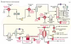
By the end of FEL, the project scope included a new vacuum tower (Fig. 1), new vacuum furnace, and new overhead vacuum system (Fig. 2). The revamp also required significant modifications to the crude preheat train and the modification or replacement of several pumps in the unit based on the revised operating conditions.
Front-end processing
The primary focus of this article is on the design and revamp of the vacuum distillation section of the Ponca City crude unit. But a major change to the back end of such a unit will necessarily impact the front end as well. Price-advantaged crudes are those available at a discount, for whatever reason. They are typically heavier and more difficult to process due to potential factors such as increased salts, sulfur, metals, or higher acid numbers or unusual distillation curves making them poor fits for most refinery configurations.
The first and most obvious limitation to processing heavier advantaged crudes is crude hydraulics. Before the revamp, crude hydraulics at the front end of the unit (from the raw feed pumps to the desalters) limited the Ponca City unit.
Although most of the preheat train in this section was already separated into two parallel paths, feed piping from tankage to the unit was a single, undersized line. This section of piping represented a significant bottleneck and was modified to use an existing line in parallel, thereby providing added hydraulic margin to allow the feed of heavier crude charge.
Additionally, exchanger and controls modifications were implemented to allow higher desalter temperatures with heavier feeds, which was required to maintain desalter performance. The first stage desalter pressure relief valve was modified to a pilot operated valve, allowing operating pressure to be pushed closer to set pressure without valve chattering and loss of feed.
At the atmospheric crude tower, several modifications were made to the bottom stripping section and boot. In the stripping section, the existing trays were replaced with new two-pass trays and the stripping steam rate was maximized to the limits allowed by the existing overhead system.
Furthermore, the existing atmospheric tower bottoms pumps were limited by net positive suction head (NPSH) and, therefore, the tray spacing in the stripping section was reduced to allow a higher boot operating level. These modifications maximized atmospheric-gas-oil recovery and allowed higher atmospheric bottoms rates using the existing pumps with only minor modifications.
At the intermediate flash tower, the bottoms pumps were modified (including a new motor and turbine upgrade) to allow for the greater vacuum unit charge rate. The operating level in the intermediate tower was also increased to account for greater NPSH requirements at the new pump design rates.
Vacuum tower design
The definition of a “deep cut” design is somewhat relative, based on a specific refinery’s experience, feedstock variation, and downstream product limitations. The design point for “deep cut” can range anywhere from 1,000° F. to as high as 1,100-1,150° F.1 2 In any case, the main idea is the same-to cut “deeper” into the vacuum resid bottoms with the objective of recovering a high proportion of vacuum gas oils, while minimizing the vacuum tower bottoms rate to downstream units.
For the Ponca City revamp, the design cut point was based on a target of 1,050° F. This was the basis for process and equipment design, although project economics were considered at a value slightly less than 1,050° F. to allow for feedstock uncertainties.
The vacuum tower design was critical for meeting the project objective of a “deep cut.” The sizing basis for the vacuum tower was unique and illustrates the type of design considerations that must often be made in a unit revamp.
Capital cost constraints, combined with plot space limitations in the existing vacuum unit, dictated that the new vacuum tower be installed in the same location as the existing tower. Constructability issues and the desire to minimize turnaround time forced the new tower to be installed on the existing foundation if possible.
A coordinated effort between process and structural engineering determined the final tower size. The existing foundation set the overall dead weight limit for the new tower with the structural design case being a liquid-full upset condition.
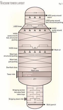
Minimum depth beds were used to limit the tower height (and therefore weight) and pump-around distributors were arranged to use every inch of available height in the tower (including installation of the light vacuum gas-oil (LVGO) collection tray and HVGO spray distributors in the upper transition section). Once the minimum height was established, tower diameter was maximized to the limits allowed by the foundation capacity.
The final analysis determined that a 22-ft diameter tower could be safely installed on the same foundation as the existing 15-ft diameter tower. Installing the largest diameter tower possible on the existing foundation would maximize the long-term return on investment and allow significant processing flexibility for future requirements.
Fig. 3 shows the vacuum tower layout for the new 22-ft diameter tower.
The vacuum tower was designed as a “wet,” or “damp,” unit using both heater velocity steam and vacuum tower stripping steam.3 4 This arrangement reduces hydrocarbon partial pressure to increase lift, and the use of velocity steam in the heater helps to ensure tube velocities are sufficient to minimize long-term coking.
The process design was based on a flash-zone pressure of 37 mmHg. This pressure was determined from an optimization analysis that considered several process parameters interrelated in the operation of a vacuum tower.
Parameters that require consideration include target cut point, heater outlet temperature, transfer-line pressure drop, pump-around duties, and product draw temperatures. Intuitively, lower operating pressures are better. At an equivalent cut point, lower pressure results in a reduced heater outlet temperature, which leads to lower oil-film temperatures in the furnace, and reduced coke formation and production of cracked gas.
These benefits, however, must be balanced with larger transfer line and tower size requirements, reduced product draw temperatures (which reduce temperature differentials in crude preheat exchangers), and a larger vacuum system. After considering all variables, the optimum flash-zone pressure was 37 mmHg. At this flash-zone pressure, a 1,050° F. cut point was possible, while maintaining a maximum heater outlet temperature of 780° F.
Koch-Glitsch LP provided the vacuum tower internals.5 The internals design was based on a coordinated effort between Koch-Glitsch, ConocoPhillips internal fractionation consultants, and Burns & McDonnell.
The inlet nozzle used a Koch-Glitsch patented “enhanced” radial vapor horn, which provided low inlet device pressure drop combined with effective velocity distribution and vapor-liquid separation.6 7
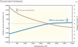
The tower boot was designed with a steam stripping section, with five two-pass fixed valve trays with an upper chimney tray distributor. The amount of stripping steam to the vacuum tower was optimized based on a balance between HVGO recovery and the capital and operating costs for incremental stripping steam. The design was based on a stripping steam rate of 2,500 lb/hr with a maximum rate of 4,000 lb/hr (nominally 3.5 to 6 lb/bbl of vacuum resid product).
Fig. 4 shows the results of the stripping steam optimization. The illustrated analysis does not reflect the impact of velocity steam. When used, velocity steam can typically offset a portion of the stripping steam required at an equivalent cut point. The relative effectiveness depends on the specific installation and requires optimization after start-up.
For this project, an estimated 1 lb/hr of velocity steam would allow stripping steam to be reduced by as much as 0.5 lb/hr at an equivalent cut point. Operating data from the first year confirms that this offset is nominally correct.
The wash section of the new tower used a “combination” bed5 consisting of a bottom section of open grid packing with an upper section of high-efficiency structured packing. This design provides general droplet de-entrainment and fouling resistance in the lower grid section combined with increased surface area and fractionation performance in the upper structured packing section.
Wash-zone design is a critical aspect of long-term vacuum tower performance. An adequate wash-oil rate is important for maintaining HVGO product quality and for minimizing wash-bed coking. The wash-oil rate at the top of the wash bed was based on maintaining a target minimum wetting rate of 0.15 gpm/sq ft at the bottom of the wash bed. This is a typical guideline, consistent with most applications in the literature.3 5
The wash-oil draw (or overflash), consisting of excess liquid from the wash section plus any flash-zone entrainment, was designed either to recycle back to the inlet of the heater or bypass directly to the tower boot (introduced just below the tower inlet device).
For the Ponca City revamp, a cost-benefit analysis for wash-oil recycle indicated a potential recovery of 0.3-0.5 bbl of HVGO/bbl of recycle. This provides a significant economic payback vs. the bypass of overflash to the vacuum tower boot, as long as sufficient vacuum heater capacity is available to heat the added recycle.
The HVGO and LVGO pump-around sections were designed with multiple layers of high-efficiency structured packing for optimal heat-transfer performance and fractionation. Both pump-around distributors were installed with a spray-type design with the LVGO collector tray and HVGO spray headers incorporated into the upper cone transition to minimize tower height.
One of the challenges of any deep-cut design is properly characterizing the heavy region of the assay (1,000-1,300° F.). These data are critical because they form the basis for developing hypothetical components to be used in process simulations and yield projections.
Several papers have stressed the use of high-temperature simulated distillation to define the true boiling point curve percent recoveries for fractions up to 1,300° F.2 3 5 8
This is a valuable method for obtaining an accurate characterization for a specific crude sample. Crude slates change, however, and the impact of slight variations in feed can create significant variations that may overshadow the apparent accuracy of a design basis assay.
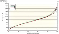
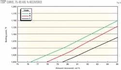
Fig. 5 compares three of the design crude slate assays considered for this project. These assays on a full 0-100% scale appear similar. A more focused analysis of the range around the 1,050° F. point, however, shows that the actual liquid-volume percent recovery could vary by as much as 2-3%, depending upon the actual crude slate (Fig. 6).
The point is not to minimize the importance of good feed characterization, but rather to illustrate that differences in actual feedstocks can introduce significant performance variations when predictions on cut point are being made. To design a truly flexible crude vacuum unit, it is critical to define a realistic range of feeds that can be expected after start-up.
Vacuum heater design
Once the vacuum tower sizing was established, the vacuum heater was designed with two primary objectives. The first, and most obvious objective, was that the heater would provide the design duty required to meet the target cut point of 1,050º F. Second, the heater capacity would be based on providing a matched design for the 22-ft vacuum tower. This criterion was used to maximize total return on investment and future operating flexibility.
The heater design used a four-pass “nested” arrangement with two passes on each wall. A four-pass design minimized project capital cost while maintaining high mass-flux rates and minimizing heater velocity steam to limit overhead vacuum system sizing.
The heater was designed for a maximum peak heat flux of 17,500 btu/hr-sq ft and an average radiant heat flux of less than 10,000 btu/hr-sq ft (actual flux at design was 9,300 btu/hr-sq ft). These values are consistent with typical recommended values in the literature.3 8
The final tube size in each pass was 10-in. diameter with 12-in. outlet connections, which is pushing the physical limits of heater designs. To maintain reasonable oil-film temperatures, the mass flux rate is kept at more than 80 lb/sec-sq ft. Velocity steam at a nominal rate of 300 lb/hr/pass keeps mass flux rates up and minimizes long-term coking tendency.
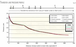
The hydraulic design was based on the 37 mmHg flash-zone pressure and a maximum transfer-line pressure drop (including the tower inlet device) of 3 psi. This pressure-drop requirement limited heater-outlet temperature to a maximum of 780º F. while achieving the target 1,050º F. cut point for the full range of design crude slates.
As with the vacuum tower, plot space constraints required that the new heater be installed in the same location as the existing. Before the turnaround, the existing foundation was extended to accommodate the expanded heater footprint.
Transfer-line design is a critical and inseparable component to overall vacuum heater design. Without a properly designed transfer line, even the best tower and heater design will not meet the unit’s performance objectives.
Design of the transfer line proved especially challenging due to the existing layout, which positioned the heater and tower in relatively close proximity and in direct line with one another such that there were few alternatives for providing for thermal expansion. Several transfer-line routings were analyzed using a coordinated effort between process, structural, and pipe stress engineering.
Fig. 7 shows the layout of the final transfer-line design.
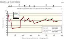
Transfer line hydraulics were designed with a target maximum velocity of 80% of sonic for the vapor phase.
Figs. 8 and 9 show the transfer-line velocity profile and calculated pressure profile from the heater outlet to the vacuum tower inlet.
null
References
- Schneider, D.F., and Musumeci, J., “Deep Cut Vacuum Tower Processing Provides Major Incentives,” Hydrocarbon Processing, November 1997, pp.83-89.
- Golden, S.W., Villalanti, D.C., and Martin, G.R., “Feed Characterization and Deepcut Vacuum Columns: Simulation and Design,” presented at the AIChE Spring National Meeting, Apr. 18-20, 1994, Atlanta, paper 47a.
- Nangia, K., Schulte, D., and Shargay, C., “Design and Revamp Vacuum Units for Maximum Return,” presented at the NPRA Annual Meeting, Mar. 26-28, 2000, San Antonio, AM-00-46.
- Golden, S.W., and Martin, G.R., “Revamping Vacuum Units for HVGO Quality and Cutpoint,” presented at the NPRA Annual Meeting, Mar. 17-19, 1991, San Antonio, paper AM-91-45.
- Laird, D., Hauser, R., and Schnepper, C., “Vacuum Tower Design Techniques for Optimum Performance and Reliability,” presented at the NPRA Annual Meeting, Mar. 23-25, 2003, San Antonio, paper AM-03-45.
- Lee, A., Chen, G., and Holmes, A., “Method of and apparatus for vapor distribution,” US patent 5106544, Apr. 21, 1992.
- Yeoman, N., Hsieh, C.-L., Marcinkowski, A.M., and Berven, O.J., “Method and apparatus using guide vanes for vapor distribution in mass transfer and heat exchange columns,” US patent 5632933, May 27, 1997.
- Barletta, T., “Why Vacuum Unit Fired Heaters Coke,” Petroleum Technology Quarterly, Winter 2002.
The authors
Ryan Spangler (rspangler@ burnsmcd.com) is a senior process engineer for Burns & McDonnell, Kansas City. He holds a BS in chemical engineering and an MS in engineering management from the University of Kansas. Spangler is a licensed professional engineer in Kansas.
Dominic Varraveto (dvarraveto@burnsmcd) is refinery process manager for Burns & McDonnell, Kansas City. He has 26 years of refinery experience including engineering, process development, start-up, and operations support. Varraveto holds a BS in chemical engineering from University of Notre Dame and an MS in engineering management from the University of Kansas. He is a licensed professional engineer in California.
Roger Schoonover is a senior process consultant for Burns & McDonnell, Kansas City. He has more than 30 years’ experience in the refining industry. Schoonover holds a BS in chemical engineering from the University of Kansas.
Tom Hanke (Thomas.A.Hanke @conocophillips.com) is a lead process engineer for ConocoPhillips, Ponca City, Okla. He has 26 years’ experience, spanning both upstream and downstream process design and operations engineering and was coordinator of front-end engineering and development for the No. 1 crude unit revamp project. Hanke holds a BS in chemical engineering from Texas A&M University. He is a licensed professional engineer in Oklahoma.
Based on a presentation to the National Petrochemical & Refiners Association Annual Meeting, Salt Lake City, Mar. 19-21, 2006.
