ORMEN LANGE-1: Extreme subsea conditions drive concept development
The irregular seabed in the area of the Ormen Lange field, the steep slide, and difficult areas along the coastline pose extreme challenges to pipeline design. Environmental conditions are also extreme, with subfreezing seabed temperatures and strong currents challenging flow assurance, pipeline installation, and pipeline integrity during the operational lifetime.
Part 1 of this two-part series describes the Ormen Lange development plan with particular attention given to the 30-in. multiphase production pipeline system and how associated challenges are being solved.
Part 2 will examine the lay methods used for Ormen Lange as well as the corrosion fatigue testing and electrical heating system employed to complete the project.
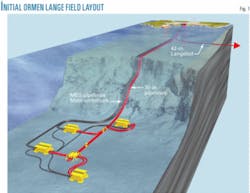
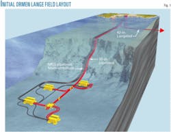
The selected development scenario for Ormen Lange is a direct subsea tie-back to a land facility on the west coast of Norway. A total of six pipelines will be laid between the onshore processing plant and the Ormen Lange field: two large pipelines for bringing the gas to land and four smaller ones for flow assurance and subsea control (Fig. 1). A new export pipeline will also be laid from the onshore plant for export to the UK (OGJ, Nov. 21, 2005, p. 66).
Ormen Lange is the second largest gas field on the Norwegian continental shelf with initial gas in place estimated at 515 billion cu m and production expected to start in 2007. The field is being developed by Norsk Hydro (18%) on behalf of the Ormen Lange partnership: Royal Dutch Shell PLC (production operator, 17%), Statoil ASA (11%), Exxon Mobil Corp. (7%), Petoro AS (36%), and Danish Oil & Natural Gas (10%). Ormen Lange lies 120 km off the west coast of Norway within a pre-historic submarine slide (Storegga) in water 250-1,100 m deep. The seabed in the Storegga slide is very irregular, with soil conditions varying from very stiff clay with boulders to soft clay.
The well stream will be transported in parallel 30-in. multiphase pipelines from the field to an onshore processing plant. The processed gas will be exported to the UK by a 42-44-in. dual diameter export pipeline.
Geography
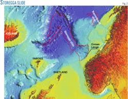
The Ormen Lange field is in the upper part of the Storegga slide, not far from its edge (Fig. 2). The subsea slide, which occurred about 8,200 years ago, is made up of sediment from the outer parts of the continental shelf and the slope beyond. The slide edge looms 200-300 m above the development area. The reservoir itself is about 1,900 m below the seabed, in water about 900 m deep.
Before development of the Ormen Lange field could be approved, the likelihood of another major slide had to be determined.
No unstable sediments have been found in the areas and it would take a new ice age to produce unstable masses at the edge of the continental shelf.
The upper headwall of the slope is about 250 m high and has an incline of 25-30°. The remaining part of the seabed, down to the main development area, has a low general incline, but the local topography is rough due to the slide blocks left by the last phase of the Storegga slide. Below a water depth of about 600 m, soft clays have filled in the depressions between the slide blocks, partially leveling the seabed.
Ormen Lange lies in a very harsh ocean environment in the Norwegian Sea where the current is very strong. Current measurements in different locations within the production area and along the pipeline routes have been performed more or less continuously since October 1999. The seabed topography in the area strongly influences currents, causing vortices that give rise to rapid variations in strength and direction.
Development plan
The chosen development concept for Ormen Lange is subsea-to-land with the possibility of future offshore compression. The onshore plant will be at Nyhamna, close to Molde on the west coast of Norway. The development scheme was selected after comparison to several offshore processing alternatives.
Two multiphase 30-in. pipelines will be installed between the deepwater field and shore. Two 6-in. monoethylene glycol (MEG) pipelines for hydrate and ice prevention and two control umbilicals will also be installed.
The topography from Nyhamna to Ormen Lange significantly narrows the area that can be selected for pipeline routes. The 30-in. pipelines will be installed in three stages. The near shore sections, about 33 km each, will be installed in 2005 and abandoned for 2006 recovery, laid just below the Storegga escarpment in water 550 m deep.
Allseas Group SA’s S-lay vessel Solitaire will install the 30-in. pipelines up to km 99.5, with Saipem SpA’s J-lay vessel S7000 continuing to Ormen Lange. Saipem will install the spool, valve modules, and pig loop and perform all tie-ins. Stolt Offshore MS Ltd. and Subsea 7 Inc., respectively, will install the MEG pipelines and the control umbilicals.
Completion of the bulk of the subsea architecture is planned for 2006. One control umbilical will be installed in 2007.
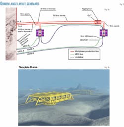
The initial subsea development consists of two eight-slot templates (A and B). Each of these templates will have integrated production manifolds connected to the two 30-in. diameter multiphase pipelines. FMC Kongsberg Subsea AS will deliver the subsea production facilities. There will be in-field MEG and umbilical lines between the two templates.
A combination of 16-in. spools connected to 16-in. in-line tees will tie the multiphase lines into the templates. The in-line tee connector assembly will be part of the initial pipelay operation, while the in-line tee valve assembly will be installed subsea. A permanent pigging loop will be installed as part of the initial commissioning work.
The pipelines will also incorporate two hot-tap tees for connecting to future templates and four hot-tap tees for the compression facility. The templates will be required in 2012. Infield flowlines and umbilicals will connect them to the existing system. Fig. 3 illustrates the field layout.
Offshore compression will be incorporated as part of future expansion plans for the field. Pressure depletion is the main drive mechanism for the Ormen Lange reservoir. Estimated recoverable reserves, however, are based on future use of compression facilities for pressure boosting as reservoir pressure declines.
The Ormen Lange subsea units and pipeline layout will be designed so that the type of offshore compression used (subsea or platform) can be decided at a later stage. The final decision on the offshore compression concept does not have to be made until years after subsea production starts.
The subsea control of gas production, MEG supply, etc., however, will remain at the onshore terminal, even if a compression platform is installed offshore.
A qualification program for the subsea compression concept is being executed. Any decision on possible implementation will not be taken until after sufficient production experience has been gained.
Research
Ormen Lange has prompted significant research. Pipeline installation across its extreme seabed topography has led to special consideration of current measurement and modeling, vortex-induced vibration (VIV) experiments, design guidelines for free-span lengths, and installation tool optimization. Norsk Hydro AS’s research center in Bergen has managed these activities since Ormen Lange development started in 1998-99.
Preliminary pipe laying analysis revealed that a large number of free spans would be needed due to the very uneven sea bottom. Some of the projected spans were too long, given the static bending moment capacity of the shoulders. The major problem, however, was the combination of such long free spans and high current velocities, which would cause VIV-induced fatigue. The significant sag of long free spans could trigger oscillation in more than one crossflow Eigen-mode.
The Norwegian Marine Technology Research Institute (Marintek) in Trondheim undertook a three-phase model test program. The first phase focused on single spans having multi-modal response. The second phase tested the response of intermediate length spans. Both phases focused on in-line VIV response, which under certain conditions can govern fatigue life. The third phase focused on multispan, multimode response, motivated by an understanding that closely spaced spans may have common Eigen-modes and thus could interact. Additionally, the Eigen-frequencies in such multi-span conditions may be closely spaced.
Modal interaction on the VIV response was derived from the tests. The procedures have since been implemented in a field-specific design guideline for Ormen Lange as well as in computer tools. They are being implemented as a DNV-recommended practice.
A comprehensive current-measurement program in the Ormen Lange area maps the near-seabed current. Focusing on near-seabed current helps establish reliable design input for the numerous pipeline free spans. Traditional current measurements-measuring and recording 10-min mean values of current speeds and directions-made up the main part of the current-measurement program. Four stations observed current through the entire water column. EOF decomposition combined with inverse FORM was used to estimate design current profiles.
Omitting directionality made this approach feasible. EOF decomposition requires too many modes to make the inverse FORM technique feasible when directionality is included.
Two series of temporal high-resolution measurements sampled current speeds and direction at 1 hz. One series also included high lateral resolution sampling. These were the first such measurements taken on the Norwegian continental shelf.
The measurements measured the turbulence characteristics of the current flow to investigate the energy content in the critical (0.1-1 hz) frequency range of pipeline free spans. The measurements confirmed that the shape of the turbulence spectra in this frequency range followed the Kolmogorov -5/3 decay law.
The Ormen Lange area proved challenging with regard to current modeling because a large area needed to be included to capture the driving mechanism of the large-scale properties, while a fine grid was needed to resolve small-scale phenomena. Furthermore, input data on the border of the model were scarce, particularly regarding temperature and density distribution across depth.
A considerable effort was thus made to improve and run numerical ocean models to describe the current pattern at Ormen Lange both qualitatively and quantitatively, with a long-term goal of laterally and vertically interpolating and extrapolating reliable current measurements.
Models with grid sizes of 20 km and 4 km covering the North Atlantic described the large-scale properties of the current, while nesting models down to a grid size of 4 m × 4 m of an area of lateral extent of 400 m × 400 m evaluated the effect of local topography.
Measured current data were reproduced with models that used the same 20-km and 4-km grid sizes. The models used climatologic and atmospheric observations from December 2002 to February 2003. Significant deviations between observed data and those produced by the numerical models indicated that the numerical models did not resolve the current in the Ormen Lange area with sufficient accuracy to produce quantitative information.
These models therefore were used primarily to sort the effects of various physical phenomena, such as the effect of passage of high or low atmospheric pressures and the behavior of the termocline and topographic steering by the slope of the headwall in the slide area.
Numerical modeling contributed to the improvement of the overall understanding of the physical processes that affect the current in the area. Numerical models also contributed to the understanding of special events and phenomena observed in the data, making them a valuable supplement to measurements of the area.
Installation tools
Pipeline installation is a major task in the development of Ormen Lange. Selecting the best location for the land terminal out of 14 nominated sites along the Norwegian west coast led to a substantial number of pipeline routes being evaluated. An optimal pipeline route was an important parameter in selecting a site for the terminal.
Work was also undertaken to find a feasible route out of the Storegga slide from the main production area. The very rough terrain in the region made the design of good pipeline routes challenging.
Picking a feasible route required narrowly controlling the length of free spans, horizontal and vertical curvature, and lateral stability. The route length was also reduced. Seabed preparation was carried out to meet these different requirements. This preparation included rock installation and dredging. The optimization of dredging and where to install rock supports is another design issue.
Route planning is usually carried out by manually evaluating the different designs and testing the alternative routes to achieve an optimal solution: a feasible route at the lowest cost.
A pipeline optimization tool was developed by Norsk Hydro’s research center to make the design of pipeline routes more effective in the initial phase. Two optimization problems were defined: finding optimal pipeline routes and finding the optimal seabed intervention. An object function describes each of the two problems. A numerical optimization algorithm automatically solves them.
Numerical route optimization
The numerical route optimization problem is formulated as:
null
Where: The optimal route (x,y) is found by minimizing the object function (J).
The problem is treated as a topography problem and the object function contains terms taking horizontal and vertical curvature, lateral stability and length into account. A full pipe description could be included, but this would make computation very heavy. Simulated annealing was used as an optimization algorithm. This algorithm also searches in directions of higher cost, making it more robust in working toward an optimal route.
Seabed intervention
The extreme topography requires significant seabed preparation before pipeline installation. The preparation includes both dredging and the installation of rock supports to reduce the length of any free-spanning pipe sections (z). At some locations dredging may be difficult and rock installation may be the only alternative. But at other locations both dredging and rock installation are possible, and how to choose between the two has also been defined as an optimization problem:
null
Where: J1 describes the cost of long free spans; J2 describes the cost of dredging; and J3 describes the cost of rock installation.
A detailed pipe model is used to get the response of the vertical pipe profile when seabed preparation is underway. Volumes of the ditches and supports are computed. The volume computation takes the uncertainty associated with dredging into account. The result is an optimal distribution of supports and trenches along the route.
Design
Ormen Lange contains mostly gas. A relatively high CO2 content and the presence of condensed water inside the pipeline led to a relatively high expected corrosion rate.
Reducing the corrosion rate to an acceptable level for the use of carbon steel as pipeline material requires the injection of chemicals. A pH stabilizer (NaOH) will be injected before any formation water is present in the well fluid, increasing its pH and thus reducing the pipe corrosion rate to about 0.1 mm/year. The method of corrosion control must be changed after the appearance of formation water. A film-forming corrosion inhibitor will be injected into the pipelines at the template to reduce the corrosion rate to less than 0.1 mm/year. A qualification program is under way to find a suitable corrosion inhibitor.
The low sea temperature at Ormen Lange (down to -1.2° C.) will likely cause top-of-line corrosion in the first part of the pipeline downstream from the templates (about 20 km). The external pipeline coating-fusion bonded epoxy and polypropylene (FBE + PP)-will be increased to 8 mm nominal thickness to reduce the condensation rate on the internal pipe wall to an acceptable level, thereby reducing top-of-line corrosion.
The 50-year design life of the project is obtained by specifying a corrosion allowance of 10 mm for the warm part of the pipeline and 7.5 mm for the cold part of the pipeline. Since no H2S has been detected in well analysis, sour service has not been specified.
Concrete coating will be applied to the shore-approach section of the 30-in. pipelines to provide stability and protection from potential impact by heavy trawlers.
The carbon steel grade specified for Ormen Lange is is SAWL 450 I FDU, in accordance with Det Norske Veritas (DNV) OS F-101. ✦
Bibliography
Fyrileiv, O., Chezhian, M., Mørk, K., Arnesen, K., Nielsen, F.G., and Søreide, T., “New Free Span Design Procedure for Deep Water Pipelines,” Deep Offshore Technology 2004, New Orleans, Nov. 30-Dec. 2, 2004.
Holden, O.M., and Paulsen, G., “Routing and Cost-effective Seabed Preparation,” International Society of Offshore and Polar Engineers (ISOPE) Conference 2005, Seoul, June 19-24, 2005.
Kirkpatrick, S., Gelatt Jr., C.D., and Vecchi, M.P., “Optimization by Simulated Annealing,” Science, Vol. 220 (1983), No. 4598, pp. 671-680.
Kleiven, G., and Eide, L.I., “High lateral- and temporal-resolution current sampling: Measurement set-up and some findings,” Offshore Mechanics & Arctic Engineering (OMAE) Conference 2005, Itaikidiki, Greece, June 12-17, 2005.
Meisingset, H., Hove, J., and Olsen, G., “Optimization of pipeline routes,” ISOPE Conference 2004, Toulon, May 23-28, 2004.
Nielsen, F.G., Søreide, T.H., and Kvarme, S.O., “VIV response of long free spanning pipelines,” Offshore Mechanics & Arctic Engineering (OMAE) Conference 2002, Oslo, June 23-28, 2002.
The authors
Asbjørn Wilhelmsen ([email protected]) is principal engineer in pipeline technology at Norsk Hydro Projects, Oslo. He holds an MS (1983) from the Norwegian University of Science and Technology.
Hilde Meisingset (hilde.christine. [email protected]) is principal engineer at Norsk Hydro Research Center, Bergen. She holds an MS (1989) and PhD (1995) from the Norwegian University of Science and Technology.
Simen Moxnes ([email protected]) is principal engineer in naval architecture at Norsk Hydro Projects, Oslo. He holds an MS (1990) from the Norwegian University of Science and Technology.
Hans Olav Knagenhjelm ([email protected]) is principal engineer in materials at Norsk Hydro Projects, Oslo. He holds an MS (1975) from the Norwegian University of Science and Technology.


