TAML refocuses on educating industry on multilaterals
TAML (Technical Advancement of Multilaterals), formed in 1997 as a joint-industry project (JIP), now aims to reinvent itself as an organization for educating the industry on the advantages of multilateral wells.
As Ray Brister, a TAML subcommittee chairman and a senior drilling and completions engineer with ChevronTexaco Corp., said "...the plan is that TAML is shifting its focus from the creator of the TAML ranking chart to an organization that focuses on education in order to advance multilateral technology."
Multilaterals have proven successful in various production applications, but members of TAML feel that the industry still does not recognize the full potential of the technology.
Estimates vary on how many wells drilled each year are multilateral candidates. Some estimate that 10% of the 60,000-70,000 oil and gas wells drilled worldwide are multilateral candidates, while others place the percentage as high as 75%.
TAML
Eighteen operators and service companies (Table 1) formed TAML in 1997 as a joint-industry project (JIP). The membership is now 14 because of mergers of several companies.
Current members include BP PLC, Baker-Hughes Inc., ChevronTexaco Corp., Halliburton Co., ExxonMobil Corp., Norsk Hydro ASA, ConocoPhillips, Schlumberger Ltd., Shell International Exploration and Production BV, Smith Services, Statoil ASA, TIW Corp., TotalFinaElf SA, and Weatherford International Inc.
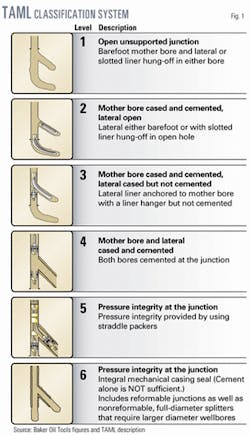
TAML is best known for developing a multilateral classification or ranking system, recently revised (Fig. 1), that serves as the industry standard for describing multilateral wells..
Brister said, in TAML's new form, its aims are to:
- Educate the industry as a whole for the next 5-8 years. The function is analogous to the milk or beef industry pushing the product not the brand to increase overall use.
- Provide operators and vendors with standardized tender documents that considerably shorten the tender bid creation, evaluation, and award time. Standardization, in addition to shortening front-end-loading time allows for more fast-tracked jobs.
- Provide a standardized screening questionnaire recognizable in the industry as the TAML multilateral classification system. This will reduce planning time and allow the operator to talk intelligently with all vendors in the same language, eliminating the need to refer to a vendor-specific widget.
- Provide a selection guide that will allow the operator and the reservoir evaluation community to garner a first look before calling the service company. A call to the service company will still be needed later.
The purpose of TAML providing the information is analogous to an operator making recommendations or offering equipment information or success-failure rates, etc. vs. a service company supplying the information.
The notion is that the information from TAML is less biased than the information coming from a service company.
- Provide canned presentations, technology, and reservoir application data, and short courses or multilateral expertise such as TAML now does with its current arrangement with Oil & Gas Journal in conjunction with conferences and forums scheduled for Galveston, Tex., in February 2003 and Moscow in June 2003, to name just two.
- Provide a website (without a database or other logistical nightmares) for people to access information. TAML's current plans will allow the public access on its web site to case history examples, membership information, organization news, upcoming events, limited technology and application updates, links, bibliography, and installation numbers on junctions and completions.
The members-only section will contain a newsletter, membership information, selection guide, questionnaire, canned presentations, technology and application updates, chat room, peer review, and minutes of meetings.
For now, TAML plans only to have corporate memberships.
Multilaterals
Multilateral wells date from the 1930s, according to various sources.
In the 1950s, the Russians drilled a multilateral with 17 laterals and obtained 10 times the production of a vertical well, according to Ray Smith, Global Operations Manager-Multilateral Technology, for Halliburton, Sperry-Sun in Nisku, Canada.
Various types of multilaterals were drilled in the 1970s-1980s, but Smith dates the more modern multilateral completions to CS Resources Ltd. working with Sperry-Sun Drilling Services and Cardium Tool Services in the Pelican Lake field, 300 miles north of Edmonton, Alta.
Smith said that in the shallow (1,340-ft depth), heavy oil (14° gravity) field, CS Resources began successfully drilling horizontal laterals in 1988 with increasing horizontal lengths that resulted in greater oil recovery.
He said this realization about the need to expose more formation to obtain more recovery drove CS Resources to develop with the two service companies a lateral tie-back system that included a casing window system with a movable gate, deflection tool, a liner hanger system, and a running tool string.
In 1993, CS Resources drilled the first test well, which included three lateral branches drilled from a 2,444-ft primary horizontal lateral. Smith said the three laterals with the initial horizontal lateral exposed more than 9,200 ft of reservoir to the well bore.
He described the completion as a well having a primary 83/4-in. horizontal lateral completed with a 7-in. slotted liner having three oriented casing windows systems at 1,850, 2,894, and 3,852 ft from which three 43/4-in. branches were drilled. Two branches were completed with 3.5-in. slotted liners, and the third remained an open hole.
As seen by the TAML classification (Fig. 1) multilaterals can range from Level 1 with an openhole sidetrack or unsupported junction to Level 6 that includes both reformable and nonreformable splitters that provide the pressure integrity. Level 5 provides pressure integrity with the downhole completion equipment.
Levels 3 to 6 provide mechanical strength at the junction.
Reformable Level 6 junctions are run with reduced leg ODs that are expanded downhole by either a hydraulic tool or a swedge process. Another method, under development is to expand the legs with pressure. Reformable Level 6 junctions have depth limitations due to their lower collapse pressure.
Nonreformable Level 6 splitters are fully formed at the surface and have much higher collapse pressure, but their limitation is that they have to be run in a larger hole size than comparable ID reformable junctions.
Smith estimated that the industry did the first Level 4 completion in 1995, the first Level 5 in 1997-98, and the first Level 6 in 1999. He also indicated that about 80% of all multilaterals currently are completed in new wells, with the remaining in old wells, usually with Level 2 and some Level 3 or 4 junctions.
Although estimates differ, to date the industry has installed about 20 Level 6 junctions. There are only six basic junction categories, but wells in the same junction category can include significantly different downhole completions equipment. Also multilateral wells are drilled with a variety of lateral geometries.
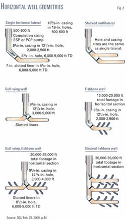
Fig. 2 illustrates some well geometries used by Petrozuata CA, a strategic association between Conoco- Phillips (50.1%) and Petroleos de Venezuela (PDVSA; 49.9%), in developing its 57,000-acre contract area in the Orinoco heavy oil (8-10° gravity) region of Venezuela.
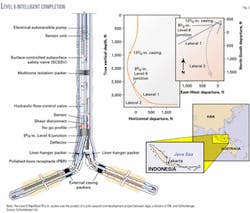
Recently some multilateral completions include new downhole tools that have become available for controlling and monitoring downhole flow. For instance, China National Offshore Operating Co. (CNOOC) off Indonesia recently drilled and completed the first TAML Level 6 well with an intelligent completion (Fig. 3).
Schlumberger Reservoir Completions provided the following information on the well, which is the NE Intan A-24 well drilled in the Java Sea in 75 ft of water.
The well has a 95/8-in. Level 6 junction with 7-in. legs and required less time to drill, just 25 days, and cost about $1 million less than the Level 3 completed AC-06 well, drilled to about the same depth with similar lateral lengths in nearby East Rama field.
The process to drill and complete the wells was as follows:
- Orient, expand, and cement in place the junction at 2,770 ft.
- Drill both lateral branches with synthetic oil-based mud. The first lateral was drilled with a 61/8-in. polycrystalline-diamond compact (PDC) bit to 4,425 ft (1,655-ft lateral), and the second to 5,105 ft (2,335-ft lateral) with a 6-in. by 7-in. bicentered bit and positive displacement motor (PDM) with a 1.83° bent housing.
- Complete the first lateral with 31/2-in. premium sand-control screens, and the second lateral with 41/2-in. premium sand-control screens. Each branch included an external casing packer (ECP) for zonal isolation.
- Install advanced well-completion equipment above the junction that included downhole hydraulic valves to control flow and sensors to measure pressure, temperature, and flow rate for each well branch.
- Install an electrical submersible pump (ESP) with a downhole well-monitoring unit and a variable-speed drive at the surface to lift the hydrocarbons to the surface through 41/2-in. tubing.
- Install a surface control and data acquisition (SCADA) system and multiphase flow meters on surface to monitor pump parameters and well performance, and transmit data to CNOOC in real time via the Web.
Issues
Multilateral design is a complex process with interacting issues and multiple solutions. For this reason, TAML proposes to develop a selection guide for the process.
Currently, various operating and service companies have selection guides although all caution that multilaterals should not be thought of as a commodity product but that one needs to evaluate available systems thoroughly with service companies before deciding on the type of completion to consider.
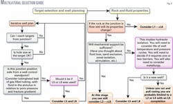
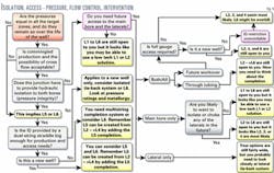
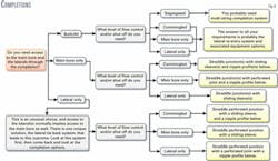
Figs. 4-6 illustrate Halliburton's selection guide.
According to Halliburton the first steps in Fig. 1 are designed to make one think about the basic well engineering, and from a connectivity point of view, the figures should provide an idea about the needed well functionality, isolation, and access issues.
Both Figs. 4 and 5 help explore the possible options from a junction point of view, while Fig. 6 looks at completion options.
