Japan frac succeeds in deep, naturally fractured volcanics
A multistage treatment successfully stimulated a well in the deep, hot, and naturally fractured volcanic rock of the Minami-Nagaoka field, Niigata Prefecture, Japan. The treatment involved six propped fracturing stages.
Initial production response was 16 MMscfd, significantly above economic target of 10 MMscfd.
Successful development of the northern part of the Minami-Nagaoka reservoir could significantly affect Japan's domestic natural gas production, although previous proppant placement in this field has proven difficult.1 2 Two propped fracturing treatments pumped more than a decade ago failed with only about 20% of the designed proppant placed before screen-outs prematurely terminated the jobs.
These treatments exhibited net pressures up to 4,000 psi before pumping any proppant. This was the highest net pressure that we have ever observed, indicating complex fracture growth.
Post-frac evaluation showed that proppant placement problems mainly occurred because of simultaneous propagation of narrow multiple hydraulic fractures. Detailed analysis of pressure build-up and production tests confirmed the diagnosis of narrow multiple hydraulic fractures, which resulted in poor (and vanishing) propped fracture conductivity and noneconomic gas production.
The new treatments in Minami-Nagaoka focused on mitigating the adverse effects of multiple hydraulic fracture propagation and the accompanying severe near-wellbore fracture tortuosity.
The project required a major mobilization of equipment and many unconventional procedure changes that led to a successful stimulation and a favorable production response.
Job procedures included the obtaining of the highest possible injection rates to enhance proppant placement, aggressive proppant slug strategy, real-time fracture treatment analysis, testing gel to ensure minimum proppant damage, careful perforation placement, extreme overbalance perforating, and use of small-grained, high-strength proppant,
Minami-Nagaoka field
Twelve producing wells in the Minami-Nagaoka gas field provide 25% of Japan's domestic natural gas production. Their productivity depends on the natural fracture system.
In the southern part of the field, the productive intervals coincide with the development of glassy rhyolite, which has abundant dissolution pores and some natural fractures. The northern part, however, lacks these glassy rhyolites and natural fractures in abundance. Consequently this area requires hydraulic fracturing.
The previous two propped hydraulic fracturing jobs failed because of severe proppant placement problems.
For the new treatment of well MHF-1, the operator's goals included:
- Obtain sustainable economic production of at least 10 MMscfd for the first 3 months of production.
- Place more proppant than in the previous two wells, where only about 27,000 lb of proppant were placed per treatment.
- Collect data for future large-scale field development.
Initial design recommendations
The stimulation and completion strategy in Minami-Nagaoka MHF-1 included numerous recommendations based on results of the failed propped fracture treatments in wells Kita Asahihara-1 and Iwanohara-1 and on experience from other oil and gas fields in the world with similar proppant placement problems as in these first two wells.
For MHF-1 the treatment goals were to:
- Conduct six propped fracture treatments targeting a 70 ft half-length (assuming rectangular fracture shape) and a 140-ft fracture height. The operator determined that a 10-MMscfd production response would be economical for further development of the northern part of the field with new wells stimulated with propped fractures.
- Obtain at least one monolayer (~0.2 lb/sq ft) of 30/60 mesh bauxite proppant to minimize significant stress-induced damage. Crushing is limited if an individual fracture contains at least a proppant monolayer.
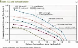
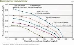
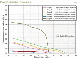
A 70-ft fracture requires the pumping of a least 80,000 lb of proppant to achieve a proppant monolayer (Fig. 1).
- Cover four main target zones that have good caliper readings and maximize permeablity-height (kh) coverage over these intervals.
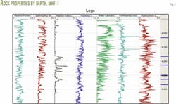
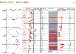
- Place perforations in high naturally fractured areas to improve production response. Peaks in the image log analysis indicate these areas (Fig. 2).
- Limit proppant ordered for MHF-1 to 500,000 lb because the proppant cannot be reused soon if the jobs screen-out. This limits the individual stage size to about 80,000 lb.
- Observe every proppant stage to "hit" perforations before increasing proppant concentration at surface. This can provide an advance warning for upcoming near-wellbore screen-outs.
This requirement makes the size of each stage at least the same as the wellbore volume, or about 200 bbl. The long proppant concentration steps and relatively small treatment size generally limit maximum proppant concentration to 4 ppg.
- Decrease pad size from >50% used in previous unsuccessful treatments to about 25% of dirty slurry volume. Perform on-site treatment evaluation to redesign treatment and evaluate proppant entry problems.3
- Select 30/60 bauxite as the proppant instead of the 20/40 mesh bauxite used in the two previous treatments because 30/60 bauxite has a smaller grain diameter that allows it to be pumped through smaller fracture width farther away from the well. It also provides a stronger layer with higher conductivity at lower proppant concentration.
- Select carboxymethylhydroxy- propyl guar (CMHPG) zirconate as the fluid, using a 60-lb/1,000 gal (ppt) base gel loading. A 70-ppt CMHPG-zirconate system should be used in case of a pressure increase reaction upon repeated proppant slugs.
- Test crosslink time on location prior to the minifrac and propped fracture treatment because crosslinking time can fluctuate with pH, especially as the premixed gel ages.
- Reduce perforated interval length from several tens of meters in the previous two wells to 6 m in MHF-1 in order to minimize fracture initiation points and to create a simpler initial fracture geometry.
- Use a cautious proppant slug strategy with various proppant slugs during minifrac and pad to minimize near-wellbore friction.
- Use high-viscosity gel pills, 120-ppt hydroxypropyl guar (HPG) crosslinked with borate, if tortuosity is too high and a near-wellbore screen-out on a proppant slug is a likely scenario.
- Use extreme overbalance perforating (EOB) to create favorable near-wellbore geometry.
Fig. 3 shows most of the equipment layout at the well location.
Equipment includes pumps with a total 13,000 hydraulic hp (hhp), 10,000 hhp maximum on-line with a minimum of 3,000 hhp as stand-by. This includes eight pumping units, seven rated (for short-term operation) at 2,000 hhp and one rated at 700 hhp.
Two pumping units required extensive modifications, while six were specially built for this job because of environmental restrictions.
CAT 3516 diesel engines provided power to the three-piece containerized units. The pumps were down-rated to 1,700 hhp because environmental requirement limited the skin temperature to less than 200° C.
All units used water-cooled exhaust manifold systems, separate from the engine-cooling unit. These two cooling units are within the same container, which sits atop the engine compartment box.
Additional fracturing equipment included a two-piece, 50 bbl/min Fracpac-type blending unit, a self-contained computer technical command center (frac van), and a quality assurance-quality control (QA/QC) fluid-chemistry lab.
Two 800-cu ft vertical storage units stored and delivered the proppant. Each unit had a modified hydraulic actuator controlled sliding gate valve to control proppant discharge onto a conveyor belt that transferred the proppant to the blending unit.
The project required the installation of high pressure (15,000 psi), 4-in. surface iron and manifolds. Additionally, the operation required a wellhead-isolation tool for protecting the production wellhead from the high treating pressures.
Completion considerations
The well completion included 5.5-in. casing and a 4.5-in. tubing in the target interval.
During the treatments, sand plugs provided isolation between the stages. They were set by bullheading them into the well at a rate of about 0.8 bbl/min below the fracturing pressure of the zone directly below the plug.
Each interval had 20 ft of perforations consisting of six shots/ft with 60° phasing. The 2.5 in., high shot density (HSD) power jet, hollow-case carrier guns used 10.7-g PJ2506 high melting explosive (HMX) charges. Average entrance hole diameter was 0.26 in. with a penetration of 10.3 in.
Fracture treatment
Original plans called for pumping 80,000 lb of 30/60 mesh bauxite during each stage, and 500,000 lb of this proppant were ordered.
The later propped fracture treatment stages, therefore, called for less proppant, and careful real-time monitoring and redesigns resulted in not using the coiled tubing unit for cleanout between stages.
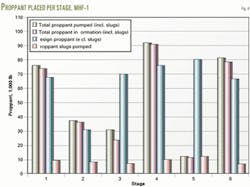
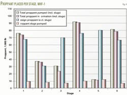
Fig. 4 shows that Stage 1 was pumped as designed, despite significant proppant placement problems. The job had excessive fracturing pressure and the rates had to be limited to remain within a maximum surface pressure.
The stage included an attempt to use a 120 ppt HPG-borate slug to remove tortuosity. This failed because of excessive wellbore friction. The gel pill could barely be flushed through the perforations at an average 1 bbl/min rate.
Injectivity finally improved when the gel pill finally broke and the fracture treatment could be continue. These injectivity problems led to an increase in pad size and the slower increases in proppant concentration. This resulted in using more fluid to place the designed amount of proppant.
The Stage 1 injectivity problems led to a significant reduction in the amount of proppant in Stage 2 because the near-wellbore screen-out potential was much higher for this zone. The zone had the highest natural fracture density along the entire well depth.
The designed treatment was placed successfully even though the tortuosity and fracture complexity were higher in this stage.
The good results from Stage 2 led to a redesign of Stage 3 so that it was more aggressive with more proppant placed using less fluid. The design cut the pad from 42% (of dirty slurry) to 27% and increased proppant concentration ramp up.
This more aggressive design resulted from significantly more fluid being required than in the original design, while being behind on the amount of sand placed.
Although Stage 3 had lower tortuosity and fracture complexity than in Stage 2, the more aggressive design likely contributed to a midfield screen-out that occurred as the 1-ppg proppant concentration entered the fracture.
Because of the relatively slow midfield screen-out pressure rise, it was possible to flush completely the 200+ bbl wellbore before surface pressure reached a maximum, and this avoided a coiled tubing run.
Based on the results of these three stages, the rest of the fracture tretments became more conservative.
The Stage 4 treatment showed remarkably low tortuosity and fracture complexities, and it was the only treatment with favorable pressure reactions to proppant slugs.
The treatment was successful. It pumped more proppant than originally designed and ended when all tanks ran out of premixed gel.
The stage placed a total of 90,000 lb of proppant, and more would have been placed easily if the fluid had been available.
Stage 5 used the same conservative design as Stage 4, but this stage screened out on a 1-ppg proppant slug during the pad for the propped fracture treatment.
The minifrac proppant slugs and the main frac pad placed 10,000 lb of proppant. Again, because of time constraints and a limited available fluid, the operator decided against refracturing this zone.
Stage 6 also had a conservative design that used all the remaining fluid and called for 66,000 lb of proppant. As in Stage 3, this treatment also advanced into midfield screen-out behavior with gradually climbing pressures starting with the arrival of the 1.5-ppg proppant concentration downhole.
The pressure increase was relatively gradual because the bridging behavior occurred at a significant distance from the well. It, therefore, was possible to pump slightly more proppant during this fracture treatment and flush the job to completion before surface pressure reached a maximum.
The job did not achieve one of the operator's original goals because it left about 150,000 lb of 30/60 mesh bauxite on location after all six stages (Fig. 4).
The encouraging production response observed during clean-up flowback cycles following most of these stages, however, eliminated this as a problem because the remaining proppant could be used in stimulation new wells in the field.
Fracture geometry
The propped fracture half-lengths obtained in MHF-1 are generally slightly less than the design goal. Fracture pressure analysis infers an average effective propped fracture half-length of about 14 m for the treatments pumped to completion (Stages 1, 2, 4, and 6). This means that at least a monolayer of proppant is present in each "equivalent" multiple fractures up to 14 m away from the wellbore.
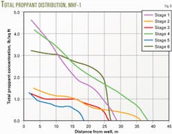
Total average propped fracture half-length was about 30 m, but effective fracture half-length was much shorter because of a relatively high degree of fracture complexity caused by multiple fracture propagation (Figs. 5 and 6) and because of less proppant placed.
Stages 3 and 5 placed only about one third of a proppant monolayer in individual fracture multiples because of a premature screen-out.
The treatments achieved 100% coverage by proppant for the four main target zones: 4,285-4,395 m, 4,225-31 m, 4,162-73 m, and 4,030-43 m TVD. The red bars on the left-hand side of Fig. 7 indicate these zones.
This assumption leads to a calculation of an average 56 m propped fracture height for each individual fracture.
Fracture pressure analysis does not provide a unique solution for fracture height growth. Recent experience with direct fracture mapping on hundreds of fracture treatments indicates that fracture height growth generally is more confined than initially thought due to composite layering effects and layer slippage.
These effects also could play a role in the Minami-Nagaoka field's thinly laminated volcanic rock sequences and cause fractures to be more confined and longer.
It is unknown whether this effect is also present in volcanic rock, but it has certainly been observed in sedimentary rocks. The current predictions, therefore, provide a minimum fracture half-length and a maximum height prediction.
With the same assumptions for fracture height growth, real-data net pressure analysis implies that propped fracture coverage of the total volcanic rock interval between 3,995 and 4,405 m is only about 69%. If individual fracture height growth is actually less due to composite layering effects, total height coverage will be even lower than 69% of the total interval.
Some of this relatively poor coverage is due to significant overlap between different fracture stages, especially between Stages 1 through 3, as these were placed relatively close together.
Another reason for poor coverage is that there was only sufficient budget for six propped fracture treatment stages. Although rock permeability varies over the entire interval, the entire interval can be considered as pay, and future projects should target 100% height coverage.
As shown in Fig. 7, coverage was especially poor at the upper end of the interval, where reservoir quality was also expected to be somewhat poorer.
Minami-Nagaoka recommendations
The analysis of the jobs resulted in the following recommendations for future jobs:
- Use continuous "on-the-fly" mixing instead of batch mixing, which requires a continuous mixer with a hydration unit volume of at least 100 bbl. This provides more flexibility with fluids. This also can save chemicals for subsequent fracture treatment in a new project.
- Consider the propped fracture stimulation of more zones (or all zones) along the entire volcanic rock interval. Production logging indicates that all zones along the wellbore contribute to production.
- Do an on-the-fly design for all stages with a preset maximum goal. Because some zones can easily take a larger treatment than others, such as Stage 2, the treatment in "easy" zones should be extended on-the-fly to allow more proppant placement for more conductivity.
Perforated intervals for subsequent treatments can be based on the treatment size previously placed. Screen-outs of small treatments should be redone after moving up a minimum distance, such as 20 m, along the wellbore.
- Stimulate several wells within one project to spread mobilization cost over more stages.
- Consider a borate crosslinked HPG fluid system for the temperature range in this well.
Borate gels provide additional viscosity at similar gel loadings of zirconate crosslinked CMHPG, and these higher apparent viscosities create larger fracture width. This may help transport proppant out farther from the wellbore before a bridging screen-out reaction occurs due to insufficient fracture width.
- Optimize further the treatments. The main engineering changes helped improve proppant placement, but possibly not as much as expected. It is critical for future project success that the operator use small perforated intervals, small proppant grains, extensive and aggressive proppant slug strategy, and real-time fracture treatment analysis with rate step-down tests.
After the six stages, we definitely understand fracture treatment behavior better, but we are still far from an optimum fracture treatment design and execution.
- Use particulates (100 mesh bauxite) both to remediate tortuosity and to decrease leakoff during the propped fracture treatment.6 Small particulates may also help reduce natural fracture damage.
Use of particulates has been successful in some North Sea and California applications in reservoirs having fracture complexity problems similar to Minami-Nagaoka.
Rock mechanical testing and modeling should be considered to determine conductivity for these particulates under Minami-Nagaoka reservoir conditions.
- Use composite plugs deployed on wireline to reduce significantly rig time (setting sand plugs) between each stage. This technique requires the tubing and liner size to be uniform from surface to TD. In this case, running a 4.5-in. liner and properly sized seals with the 4.5-in. tubing would allow a uniform ID.
- Do not use a higher-pressure system with a maximum 20,000-psi pressure limitation instead of the 15,000-psi system used in these treatments because it is not economical for these treatments and unnecessary when in an on-the-fly design.
Acknowledgments
The authors thank Teikoku Oil Co. Ltd., Japan National Oil Corp. (JNOC), and Halliburton Energy Services for permission to publish this article. F
References
1. Sato, K., Wright, C.A., and Ichikawa, M., "Post-Frac Analyses Indicating Multiple Fractures Created in a Volcanic Formation," paper SPE 39513 presented at the India Oil and Gas Conference, New Delhi, Feb 10-12, 1998.
2. Weijers, L., Wright, C.A., Sugiyama, H., Sato, K., Zhigang, L., "Simultaneous Propagation of Multiple Hydraulic Fractures—Evidence, Impact and Modeling Implications," SPE paper 64772 presented at the International Oil and Gas Conference and Exhibition, Beijing, Nov. 7-10, 2000.
3. Gas Research Institute Technical Description GRI-95/0257 on "Real-Data (Net Pressure) Fracture Analysis" (1995).
4. Wright, C.A., Weijers, L., Davis, E.D., Mayerhofer, M., "Understanding Hydraulic Fracture Growth: Tricky but Not Hopeless," SPE paper 56724 presented at the Annual Technical Conference and Exhibition, Houston, Oct. 3-6, 1999.
5. Barree, R.D., and Winterfeld, P.H., "Effects of Shear Planes and Interfacial Slippage on Fracture Growth and Treating Pressures," SPE paper 48926, presented at the SPE Annual Technical Conference, New Orleans, Sept. 27-30, 1998.
6. Britt, L.K., Hager, C.J., and Thompson, J.W., "Hydraulic Fracturing in a Naturally Fractured Reservoir," paper 28717 presented at the International Petroleum Conference and Exhibition of Mexico, Veracruz, Mexico, Oct. 10-13, 1994.
The authors
Leen Weijers is manager of technical development—FracproPT for Pinnacle Technologies. Weijers works in the calibration of fracture growth models with various fracture diagnostics, such as tiltmeter and microseismic fracture mapping technology. He holds an MS in geophysics and a PhD in petroleum engineering, both from Delft University of Technology in The Netherlands.
Larry Griffin is vice-president of diagnostic services at Pinnacle Technologies, responsible for the delivery of fracture mapping and reservoir monitoring services. These services include tilt and microseismic technologies. Before joining Pinnacle in 1998, Griffin worked in West Texas and Alaska for 17 years in reservoir, operations, and completions engineering. He hods a BS in petroleum engineering from Texas Tech University.
Hiromi Sugiyama is manager of the technical planning department of Teikoku. He has been with the company for 15 years.
Tatsuo Shimamoto is a senior reservoir engineer in the technical planning department of Teikoku. He has been with the company for 10years.
Shinichi Takada is a senior reservoir engineer in the new ventures department of Tiekoku. He has been with the company for 12 years.
King Kwee Chong is Halliburton's China operations manager for production enhancement, cementing, and completions. Chong has over 26 years of industry experience in hydraulic fracturing, acidizing, nitrogen service, coil tubing, and cementing. He holds a BS in computing.
John M. Terracina is a global advisor specializing in production enhancement at Halliburton's Technology Center in Duncan, Okla. He joined Halliburton in 1980 after earning a BS in chemistry from Northeast Louisiana University.
Chris Wright is the founder and president of Pinnacle Technologies and vice-president of CarboCeramics. Wright has spent the last 14 years working on various aspects of hydraulic fracturing, including technology development, consulting and services, and teaching. He was an SPE Distinguished Lecturer in 2000-01. Before founding Pinnacle in 1992, he led the development of the Fracpro system.
