Canyon Express touts industry firsts, shared infrastructure for deepwater gulf development
In September 2002, TotalFinaElf E&P USA Inc. announced first gas on the industry's deepest subsea project to date.
The historic project in more than 7,200 ft of water in the Gulf of Mexico represents the cooperative effort of three primary operators—TotalFinaElf, Marathon Oil Co., and BP PLC and field co-owners Pioneer Natural Resources Co. and Nippon Oil Exploration USA Ltd.—and has drawn on the subsea expertise of Houston-based INTEC Engineering, TotalFinaElf's and its partners' contractor for front-end engineering and project management services.
Shared infrastructure
The Canyon Express project touts several industry firsts and creates an industry model for continued marginal deepwater development. The project expresses TotalFinaElf's concept of shared infrastructure to facilitate development of several deepwater fields.
The project also expresses operators' recognition of the value of cooperation to develop deepwater marginal fields that demonstrate reservoir compatibility. And finally the project rests on the willingness of the US Minerals Management Service to consider the co-mingling of production flow from multiple operators' fields.
Industry confidence in the reliability and accuracy of technology designed to measure gas at the wellhead has contributed to the viability of the project philosophy. The flowline design further contributed to the project cost savings and operational reliability of the entire system.
System features include:
- An innovative daisy-chain flowline design with in-line sleds.
- A flow-assurance system addressing the complexity of a multi-company ultra-deepwater development.
- State-of-the-art hybrid fiberoptic-electrohydraulic subsea control system with umbilicals designed to meet the reliability requirements of the long-distance production system
- Subsea multiphase flow meters to ensure accurate flow allocation among three deepwater operators and five mineral rights owners
- Round-trip pigging to ensure timely removal of wax build-up in the flowline
Project
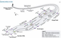
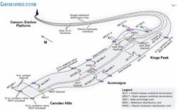
The Canyon Express Pipeline project calls for development of nine subsea wells from three deepwater fields: Camden Hills, operated by Marathon in 7,200 ft of water; Aconcagua, operated by TotalFinaElf in 7,100 ft of water; and King's Peak, operated by BP in 6,200-6,400 ft of water (Fig. 1).
Camden Hills includes two wells; Aconcagua, four wells; and King's Peak, three. Estimated peak gas production from the three fields is 500 MMscfd.
null
INTEC Engineering's contributions to this project include engineering-design and assistance with project management for the Canyon Express development operated by TotalFinaElf and jointly owned with Marathon, BP, Pioneer, and Nippon.
INTEC's project services have included:
- Procurement support and testing of subsea equipment.
- Preparation of bid packages, including subsea installation, review of all bids, and recommendations to TotalFinaElf.
- Technical and personnel support to the construction management team.
- Vendor contract management.
- Assistance with full-system system integration testing (SIT), hook-up, and commissioning.
INTEC's front-end engineering services for the subsea development have included:
- Flow assurance and system engineering.
- Subsea equipment specifications.
- Flowline design and routing.
- Steel risers at the shallow-water host platform.
- Subsea well tie-in jumpers.
- Subsea control system and umbilical design.
- Subsea multiphase flow meters.
- Intervention-workover control system.
The effort for this project and its owners has required a cost-effective approach to the development of these deepwater wells. As a result, the Canyon Express development today produces from the ultra-deepwater reservoirs into a common subsea, multiphase gathering system.
The daisy-chain design for gas gathering facilitated this concept, resulting in dual 12-in. flowlines totaling 114 miles transporting the gas to a shallow-water host platform on East Main Pass Block 261.
The flowlines are separated via a pigging valve upstream of Mississippi Canyon Block 305-1, the furthest upstream well on the west flowline. The pigging isolation valve is opened and closed by remote actuation at the platform. During normal operation, the pigging valve is closed, allowing for independent operation of each flowline.
Flowline routing is dictated in large part by the location of each well. The design incorporates in-line sleds welded to the flowline and close to each well. The daisy-chain design, incorporating the in-line sled, represents a first for ultra-deepwater and provides a viable, cost-saving alternative to the traditional installation of central manifolds, with "hubs" for in-field flowlines tying back to a main pipeline.
While the initial field development concept called for manifolds for each of the three fields, with in-field flowlines from the manifold to each of the wells, the cost for such a scheme proved excessive. The daisy-chain concept initiated its own challenges, however, with increased planning for the operational management of the development.
Meanwhile, the flowline tie-ins of the wells are as follows:
- East flowline—two wells: Aconcagua at Mississippi Canyon Blocks 305-3 and 305-4; two future wells: King's Peak at DeSoto Canyon Blocks 177-2 and 133-3.
- West flowline—two wells: Camden Hills at Mississippi Canyon Blocks 348-1 and 348-2 (Although attached at the deepest end of the West flowline, these wells flow toward the East flowline because the pigging valve upstream of the well at Mississippi Canyon Block 348-2 remains closed during normal operations.); two wells: Aconcagua at Mississippi Canyon Blocks 305-1 and 305-2; three wells: King's Peak at Mississippi Canyon Blocks 217-3 and 217-2 and DeSoto Canyon Block 133-2.
The flowlines run about 60 ft from each well, with the subsea trees connected to the in-line sleds via 6.625-in. steel pipe jumpers, thus creating an "omega" configuration.
Production from each of the wells is primarily methane with varying volumes of water and condensate, with methanol injected at the wellhead for hydrate inhibition.
Maximum production rates from each field range from 100 to 225 MMscfd of gas, with about 200-450 b/d of condensate; 300-900 b/d of water; and 450-1,400 b/d of methanol.
Flowline design
The design and analysis scope for the project addressed all aspects of offshore flowline design and included a flowline hydrotest pressure of 7,450 psig. The thorough design analysis facilitated the selection and ordering of line pipe while providing the partners with confidence in the project feasibility.
Aspects of the analysis included flowline size and grade selection (12.75-in. OD, API X-65, seamless), bottom-roughness analysis, on-bottom stability, pipeline crossing analysis, buckle propagation and buckle-arrestor design, cathodic-protection design, flowline installation analysis—with and without in-line sleds, minimum route curvature, offshore survey support, route selection, and jumper design.
To address varying pressure and buckling issues along the deepwater route, the project team opted for three separate wall thicknesses of non-API standard size, rather than a single 0.900-in. WT. This decision saved the project $2 million in steel.
At the deepest end in 7,280-2,400 ft of water, a 0.800-in. WT is applied; for 2,400-1,300 ft of water, a 0.855-in. WT is used; and for the shallowest end of the flowline at 1,300-299 ft of water, 0.900-in. WT is required. The riser is 1.125-in. WT.
The jumper is 0.562-in. WT, with consideration for potential buckling propagation. Other assessments for flowline-to-well jumper design included flowline movement, available tolerances for placement of the in-line sleds, and the weight of the multiphase flow meters (MPFM), one for each well to measure gas flow, which attach to each of the nine jumpers.
Flowline installation
Meanwhile, the project team pursued a totally open bid strategy for the flowline installation contract, leaving J-lay, S-lay, and reel-lay options available to the contractors.
null
This approach facilitated a thorough evaluation of all lay methods, as the project involved installation of all the in-line sleds in more than 6,000 ft of water within precise tolerances while at the same time achieving the specified route curvature.
TotalFinaElf contracted Saipem Inc. to execute the construction and installation of the Canyon Express project. The Saipem contract included umbilical manufacturing and installation and the flowline installation contract scope of work, which included flowline installation; sled design, manufacturing, and installation; jumper design, manufacturing, and installation; and subsea tie-in at the host platform.
Saipem awarded the flowline installation portion of work to SaiBOS—a joint venture of Saipem and Bouygues Offshore SA.
SaiBOS awarded European Marine Contractors Inc. (EMC) the shallow water pipelay from Canyon Station to Viosca Knoll Block 736 in 650 ft of water. EMC's anchored S-lay barge Castoro 10 installed two 5.1-mile sections of the dual 12-in. flow system between Oct. 26 and Dec. 3, 2001.
The biggest obstacle for the shallow-water pipelay was the congested seafloor. EMC used lifting buoys at each anchor line crossing any existing pipeline to ensure proper clearance.
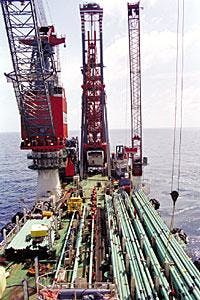
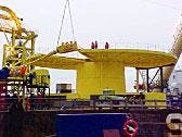
SaiBOS' field development ship J-lay vessel (Fig. 2) installed the deepwater portion of the flowline from Viosca Knoll Block 736 to Mississippi Canyon Block 348 in 7,280 ft of water from Jan. 15 to July 31, 2002. This portion of the work included crossing one existing pipeline in 900 ft of water and crossing two pipelines and one umbilical in 5,000 ft of water.
The development ship also installed 10 in-line sleds and 2 termination sleds and the 12-in. pigging loop jumper to close the loop at Camden Hills (Fig. 3). SaiBOS subcontracted Sonsub Inc. to perform the 6-in. well jumper manufacturing and installation, using the Midnight Hunter vessel, and to perform all remotely operated vehicle (ROV) work.
The greatest difficulty for the development ship was the sled installation; however, the J-lay installation method helped to minimize flowline stress. Extensive planning and detailed installation engineering further facilitated installation within tight tolerances and with minimum pitch and roll.
One of the significant challenges with this effort included the weight of in-line sleds. Weight of the sleds ranged 28,000-43,000 lb, which affected management of the flowline catenary, in terms of verticality or rotation potential. Saipem chose to use full buoyancy within the catenary to offset the sled weight.
The King's Peak sled installation involved an 8,000-ft curve in approximately 6,400 ft of water. At King's Peak, Saipem installed three in-line sleds that were in the flowline catenary simultaneously, with two of the sleds installed 3,200 ft apart within the curve. In the Aconcagua field, two sleds were installed in the catenary some 3,700 ft apart in 7,100 ft of water.
Achieving these feats required proper attitude of the sled in the water column. Saipem, therefore, positioned the center of gravity of the sled as close as possible to the pipe axis and with sufficient buoyancy to facilitate an up-righting moment when the sled entered the bottom part of the catenary.
Another challenge with the sled installation involved landing each sled in its target box, as defined by pre-installed mudmats. To ensure the success of this operation, Saipem used acoustic transponder arrays on the seabed, allowing the sled to be integrated in the correct location in the catenary.
The jumper, which connects the subsea tree to the flowline, had its own set of installation challenges. Each Canyon Express jumper incorporates the MPFM, which weighs 4,600 lb. While the original MPFM design estimated a system weighing 3,500 lb, enhancements including triple redundancy instrumentation as opposed to cost-risk prohibitive ROV-replaceable instrumentation packages, use of special manifold blocks to avoid potential water ingress, and corrosion protection on the flow meter all influenced the final weight.
Joint team efforts accommodated the increased weight, performing a detailed finite-element analysis of each jumper. To facilitate installation, Saipem added a counterweight below the jumper spreader bar to support the MPFM and removed the counterweight upon completion of the jumper connections.
Special attention for dynamic effects during lowering and landing the jumpers also was necessary, with jumper installation proceeding smoothly using a buoy installed on top of the spreader bar.
Production equipment
Major components of the subsea production equipment include the christmas trees, the christmas tree choke valve, and the flowline connection system and flowline valves for each of the three Canyon Express fields. As with other aspects of the Canyon Express project, the extreme water depth provided the greatest challenge for both the qualification process and the installation phase of the project.
null
The deepwater drillship Transocean Discoverer Spirit completed the wells and installed the subsea trees and chokes during 2002. The logistics of coordinating this installation process at various field locations while simultaneously orchestrating the flowline installation with the J-lay vessel called for meticulous pre-planning.
During the design phase, INTEC prepared individual equipment packages and specifications for the system components and assisted the partners in the technical review of the bids, with Cameron winning the contract. Separately, the project team supervised qualification testing of those components that might be affected by the ultra-deepwater.
Each christmas tree is a 4 in., 10,000-psi assembly designed to meet API PSL 3, Material-Class EE requirements. The tree system and structure is an open-architecture design, which allows an ROV to work on all four sides of the equipment, as well as the roof. This feature allows interventions to be carried out on the control module, the choke valve, and the chemical metering valves.
The major tree assembly components include the structure, the spool body, the tree gate valves, the valve blocks, the wellhead connector, the tubing hanger, and the internal tree cap (Fig. 4).
Only the valves, however, required qualification testing one of each size of valve and actuator for operation and the local environment. The testing process included all relative support equipment necessary to install or recover the equipment.
The christmas tree's choke valve is a hydraulically operated subsea retrievable insert assembly rated for 10,000-psi working pressure. Qualification tests on the choke valve demonstrated that it successfully met all the requirements.
Tests on Cameron's flowline connection system and pipeline valves proved their suitability for the intended service. Further, the flowline connection system meets the American Petroleum Institute's and project's specifications, with all of the equipment meeting design and operational criteria.
Control station
The master control station (MCS), installed on the Canyon Station platform and operated by TotalFinaElf's Canyon Express liaison officers, provides for the total system operation for the shared subsea infrastructure, including the critical MPFM to facilitate the co-mingled production flow.
INTEC assisted the operator in the development and commissioning of the MCS and the associated umbilical system.
The MCS provides fiberoptic, hydraulic, chemical, and electrical communication from the host platform to the various wells via a single control umbilical. A separate single methanol distribution line facilitates methanol supply to each of the three fields via central distribution units, in-field umbilicals, and flying leads. Importantly, the hybrid fiberoptic-electrohydraulic subsea control system accommodates the requirements of all the operators.
To facilitate reliable operations over the 56-mile umbilical length, the design team proposed a single, continuous control umbilical without the assistance of conventional electrical system with signal boosters. This decision, made in the early preliminary design phase, reduces the risk of operational failure at various points of connection in ultra-deepwater.
Kvaerner Oilfield Products Inc. facilitated the cable development using extra-thick insulation to reduce capacitance and signal attenuation in the communications lines.
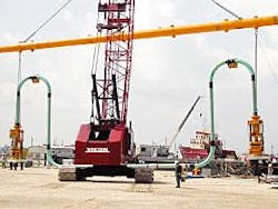
Sonsub completed the precision installation of the subsea control system components and umbilical terminations (Fig. 5), using its multiservice construction vessel Maxita to lower and lay down the equipment within 6 ft of target (Fig. 6).
The electro-hydraulic distribution units (EHDUs) proved to be the greatest installation challenge, with each unit weighing 52,000 lb and requiring deployment from a single wire in 7,000 ft of water. The two EHDUs are used to direct services from the main umbilical to each subsea well and are installed at King's Peak and Aconcagua fields.
The remaining subsea components include subsea control pods mounted on each subsea tree, with associated instrumentation; a network of 12 main and in-field electro-hydraulic steel tube umbilicals, complete subsea umbilical terminations; and bridge jumpers hydraulically to connect individual umbilical segments to each other or to the EHDUs.
Additional subsea components include 85 steel tube, thermo-plastic, electrical, optical flying leads varying in length from 120 to 240 ft.
The MCS incorporates operation of the single methanol distribution line and the electrically powered chemical-injection metering valves to control and monitor the flow of chemicals and methanol to each well. Using these flow measurement devices, the operators know exactly how much methanol is injected into each well.
The MCS also operates a downhole hydraulic valve system for each well that incorporates dual-zone sliding sleeve valves, allowing the operators selectively to produce from different reservoir zones. This emerging technology facilitates liquids management, a key flow-assurance issue for the Canyon Express development, while extending the life of each well.
Flow assurance
Operation of the Canyon Express development focuses on serving the three fields without any field or well within each field taking on the performance risk of another field. Flow assurance for the entire system involves three major areas: volume allocation and pipeline sizing; operability of the production subsea system; and subsea multiphase flow metering.
While study and development of these interdependent strategies has provided the partners with operating parameters, the partners recognize that the system will remain dynamic because of distinctions in both reservoir characteristics and preferred operating strategies. The partners further agree that shared infrastructure requires flexibility and continued communication to ensure viable asset management for everyone's benefit.
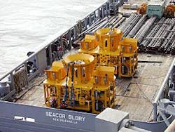
The main umbilical carousel for the Canyon Express flowline loads out from Aker Kvaerner's Moss Norway yard onto Saipem's Maxita offshore construction vessel. The umbilical termination unit is destined for the Marathon-operated Camden Hills gas field in 7,250 ft of water in the gulf. The load out included the 56-mile long main umbilical on the carousel, eight in-field umbilicals on red installation reels and various spare lengths on blue transportation reels (Fig. 5; photo from INTEC Engineering.)
Volume allocation. First, to optimize and equitably establish the operation of the Canyon Express system over the life of the development, the project team integrated the respective reservoir models from each operator using a thermal-hydraulic steady-state model for the dual flowlines.
This effort, focused on how best to maximize recoverables and how to identify each operator's volume allocation and excess capacity over time, included consideration of reservoir decline, production liquids, methanol injection, topside facility constraints, and decreasing host platform arrival pressure.
The project team simulated operation over the field life of the development using the Baker-Jardine Field Planning Tool and PipeSim-Net model.
The model uses basic reservoir modeling and decline via tank models for each reservoir while considering limitations of the host facility, including platform compression, host platform arrival pressure, well production rates, etc. The team verified the results against the reservoir simulations from the respective operators for the three deepwater fields.
The operating strategy optimizes the production of the weakest pressure well on an individual flowline, with all other wells tied-in to that flowline operating choked at the wellhead. If not sufficiently choked back, the stronger wells can overwhelm the weaker wells, thus restricting their production or potentially shutting them in.
To optimize production from the weakest pressure well, the system operation calls for dropping the flowline outlet pressure to reduce pressure throughout the flowline.
When the system can no longer sustain the maximum level of the arrival flow rate, platform arrival pressure is reduced to maximize production as dictated by the flowline and compression capacity.
Each flowline has a dedicated 7,000-hp compression facility to accommodate this operating strategy.
The Canyon Express commercial operating philosophy is consistent with the overall operating principles established among the operators, with volume allocation for each field based on each operator's equity interest percentage in the development asset.
The volume allocation is calculated using the following equation:
vol allocated =(equity percentage) x (vol west + vol east)
Allocated volume for an individual field equals the total calculated capacity for both flowlines multiplied by equity share. Over time, the volume capacity allocated to each operator decreases due to decline in reservoir pressure and subsequent decrease in flowline pressure and host platform pressure.
The percentage of volume capacity for both flowlines allocated to each field, however, remains constant, reservoir pressures permitting.
In short, the calculated allocated volumes and flowline pressures formulate the operating agreement for Canyon Express. Further, predicted production curves for each operator ultimately accommodate the curve of allocated volumes, with reservoir performance not necessarily corresponding to equity interest.
Subsea system operability. To verify operability of the subsea production system and to define the operational procedures, the project team analyzed the flowline gas-liquid behavior under various operating scenarios. Studies included transient simulations to determine the impact of flowline liquids (i.e., potential slug size and rate of liquid flow) as they proceed to the topside facilities for separation.
The transient simulations also evaluated system performance during both upset and normal conditions. The team used Scandpower's OLGA-2000 to perform the simulations, identifying scenarios and time points where potential problems due to liquids could be expected and appropriate techniques for controlling any associated liquid slugs.
In general, as gas rate and reservoir pressure decline over time, liquid loading in the wells and flowlines increases, leading to various production challenges for liquid slugging during both normal production and transient situations, i.e., system restarts, flow increases, etc.
In terms of liquid handling, however, increased gas in the flowline, as opposed to systems start-up, is actually more critical to the operations management.
The studies conclude that for steady-state operations, liquid slug volumes do not exceed the liquid-handling capability of the host platform separator. For non-steady-state scenarios in which liquid flow may exceed topside capacity, the studies conclude that slug volumes could be mitigated operationally.
For example, during the ramp up of a well, the operator can achieve control of liquid rate at the platform by slowly ramping up the wells. This process, however, will require longer ramp up times.
Differences in reservoir fluid characteristics and well water contents make continual monitoring of the amount of liquids in the flowline necessary. Operator use of OLGA simulation runs; however, help to facilitate estimates of ramp up times.
Multiphase flow metering. The design of the Canyon Express system includes subsea MPFM to ensure accurate flow allocation among the three deepwater operators, each having different operating regimes and varying production rates from the multiple zone completions.
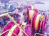
More than 11 miles of eight in-field umbilicals (on red installation reels) and two spare lengths (blue transportation reels) for the Canyon Express development load out onto Saipem's Maxita offshore construction vessel destined for ultra-deepwater in the Gulf of Mexico. The Canyon Express project calls for development of 10 subsea wells and cooperative effort of three primary operators: TotalFinaElf E&P USA Inc., BP PLC, and Marathon Oil Co. (Fig. 6; photo from INTEC Engineering)
The development of the metering system, which measures gas and total liquids (oil, water, and methanol) involved extensive testing at the Southwest Research Institute in San Antonio to verify measurement performance and at the Slingsby facility in North Yorkshire, UK, to confirm hyperbaric integrity.
The Canyon Express partners selected the Dualstream II meter for wet gas measurement. The Dualstream predicts liquid fraction of a wet gas stream with a venture meter as the primary device. While the system is proven, the Dualstream required extensive testing to ensure its continuous, reliable operation in ultra-deepwater.
Other factors affecting use of the meters included the transportation and installation of the system, operational redundancy, and ROV-accessibility for any necessary maintenance.
The testing program addressed areas including marinization of the meter in terms of the unit's readiness to withstand the hydrostatic pressure of seawater acting on each of the meter components and the robustness of the system to sustain the high-pressure wells.
Other issues included welding and corrosion protection. Calibration testing further evaluated the wet gas meter's ability to detect incrementally low liquid fractions throughout an operating range of gas flow rates over a variety of flowing conditions.
Implementation of the MPFM system involved integrating the results of flow loop tests into an algorithm used to compute individual mass flow rates. The team subsequently programmed this information into the MCS and tested the system. Following initial start-up in August 2002 and several weeks of production, the project team concurs that the meters are adequate for gas measurement and allocation.
The author
John Stearns is a project director with INTEC Engineering, responsible for the project management of pipeline, subsea, and facilities projects. He is currently INTEC's project director for the BP Mardi Gras project in deepwater Gulf of Mexico and previously served as INTEC's project manager of the TotalFinaElf Canyon Express project, also in deepwater gulf. Stearns has more than 24 years' experience in design and construction of onshore and offshore oil and gas pipelines, deepwater subsea production systems and conventional onshore and offshore production facilities. He has 6 total years with INTEC, most recently joining the company in 1999. From 1990 to 1992, he served as a project enginee. From 1992 to 1999, he served as a senior project engineer with ABB Lummus Inc. in Saudi Arabia for Saudi Aramco. Stearns holds a BSc in civil engineering from the University of Texas at Austin and is a registered professional engineer in Texas.
