Multilateral, intelligent well completion benefits explored
In general, a study found that multilateral wells perform better than single horizontal wells. but the best technology to use depends on specific reservoir characteristics, drilling conditions, and economic considerations.
The study involved a comprehensive evaluation of multilateral wells for water-drive reservoirs and accounted for friction and hydrostatic pressure losses through the horizontal and vertical sections.
The work compared multilateral well performance with conventional horizontal wells. It considered both natural flow situations, in which an optimal tubinghead or separator pressure typically controls the production, and artificial-lift applications, while a constant liquid rate, constant bottomhole pressure (BHP), or a combination of both control the production.
Studied were wells in the Gulf of Mexico, North Sea, Middle East, and South America, in which operators have implemented horizontal and multilateral technologies on a field scale.
The reservoirs studied have 9-32° gravity oil, 5,000-13,000 ft depths, and 2,000-8,000 ft horizontal sections. The offshore reservoirs are in shallow-to-deep water, and have normal, abnormal, and subnormal pressures.
Multilaterals
Multilateral technology continues to expand, with some fields being redeveloped as multilateral wells in different parts of the world.1-3 In addition to incremental oil production and multiple-target options, multilateral wells offer the added cost benefit of slot conservation in offshore applications.4
When this technology is combined with subsurface flow-control valves, the intelligent multilateral well can increase incremental hydrocarbon recovery.5
Published studies cover important aspects of multilateral technology such as predicting performance,6 determining pressure drop through horizontal and vertical sections,7 providing comparisons with horizontal wells,8 and determining effects of water-drive mechanisms.9
Other publications deal with aspects of intelligent completions such as minimizing coning in horizontal wells,10 optimizing valve settings in multilateral wells,11 and developing fields with horizontal12 and multilateral wells.5
Reservoir model
The study used a numerical reservoir simulator coupled with a multisegment well option to account for hydrostatic and pressure losses in the horizontal and build sections. This model was built from the reservoir to the multilateral junction.
From the junction to the surface, modeling involved the conventional format of tubing tables generated by standard correlations and coupled with the simulator as look-up tables. This process is more accurate and less computer intensive than building a multisegment model from the reservoir to surface.
The model set the tubinghead pressure (THP) at a constant 200 psia in the natural flow cases.
Two common multilateral configurations are Technical Avancement of Multilaterals (TAML) Levels 3 and 6. Level 3 junctions provide mechanical integrity but not hydraulic isolation, whereas Level 6 junctions provide both mechanical integrity and hydraulic isolation.
Level 6 systems, however, lose a casing size. The 95/8-in. Level 6 junction limits the liner to a 41/2 or 5-in. diameter. A single horizontal well would have a 7-in. liner in an 81/2-in. production hole below the 95/8-in. casing shoe.
The study identified various well configurations with a short-hand notation.
For a horizontal well it identified the near-reservoir well configuration simply by its reservoir section length and production liner size.
The Level 6 multilateral description includes the production liner sizes of each branch, the reservoir section length of the first branch, separation distance between the two heels, and the reservoir section of the second branch, in that order.
Thus, 2k, 7-in., single horizontal defines a single horizontal well with a reservoir penetration of 2,000 ft and a 7-in. liner. And 2k-1k-2k, 41/2-in. Level 6 defines a multilateral Level 6 well with two 2,000 ft branches, separation distance of 1,000 ft, and 41/2-in. production liners.
Level 3 multilaterals had a similar definition.
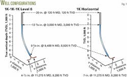
The study included only two-branch multilaterals, 180° apart (Fig. 1).
One important issue when comparing horizontal wells and multilaterals is the length of the horizontal sections. For any well, practical operational issues limit this parameter.
The study assumed that each multilateral branch can reach the same length as the horizontal well. This premise assumes that each branch will have the same horizontal drillability. For example, a 1k, 7-in.horizontal well is compared with a 1k-1k-1k, 41/2-in. Level 6 or a 1k-1k-1k, 7-in. Level 3.
The Level 3 comparisons used the same well diameters for both the multilaterals and the horizontal well.
Multilateral modeling
This study used ECLIPSE software with the multisegment option for reservoir simulation; FloViz software for 3D visualization, PIPESIM total production software for nodal analysis, and VFPi vertical-flow performance software for generating well hydraulic tables required for modeling to surface.
Wellbore trajectories can be complex. To be consistent with actual drilling proposals, the study generated two wellbore profiles with horizontal drilling software. It positioned the junction at a 45° inclination angle and the angle-building rate at 6°/100 ft for the 2,000-ft separation distance case and 11°/100 ft for the 1,000 ft separation distance.
Segmentation is difficult manually because the junction position can be several hundred feet above the reservoir. To solve this problem, the study used well data transformation software schedule for automatically generating the segments and the well connections.
A 100-ft segment length was selected for most segments in the horizontal section. Fig. 2 shows one segmentation example with the grid connections generated for the Level-6 configuration with separation distance of 2,000 ft and lateral length of 2,000 ft.
Each horizontal section has 22 segments and connects to 10 grid blocks, resulting in 95 total segments for the two branches.
Level 6 junction
Schlumberger's Level 6 junctions are available in 95/8 and 133/8-in. sizes.
The 95/8-in.junction has two 7-in. outlets, allowing drilling with 61/8-in.bits and setting of 41/2-in. OD liners, while the 133/8-in. has two 95/8-in. outlets, allowing drilling with 81/2-in. bits and installation of 7 or 75/8-in. liners.
The study compared the production performance of these two junctions to quantify the effects of junction size.
The parameters included 250-md horizontal permeability, 0.1 kv/kh (ratio of vertical to horizontal permeability), 29° gravity oil with 0.96 cp viscosity at 4,000 psia. The multilateral well has a 1k-1k-1k configuration with a junction at 8,854 ft TVD (9,416-ft MD). The horizontal sections are at 9,208 ft TVD.
The model assumed a constant 10,000 bo/d production from each branch.
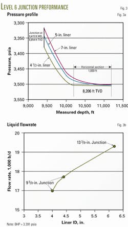
Fig. 3a shows the pressure profiles. The horizontal sections have pressure drops of 20, 12, and 2 psia for the 41/2, 5, and 7-in. liners, respectively. The corresponding pressure drops in the build section from the toe to the junction are 167, 149, and 127 psia.
The 133/8-in. junction operates at a well-toe pressure of 3,506 psia, which is 4 psia greater than the 95/8-in. junction. This results from a larger wellbore generating a higher productivity index.
Fig. 3b plots the results of quantifying the friction effects in terms of production. The study used the same model and well configurations to calculate the liquid flow rates for a constant 3,391 psia BHP.
The 133/8-in. junction allows 14% more oil to flow than the 95/8-in. junction with 41/2-in. liner and 9% more than the 5-in. liner case. For the 95/8-in. junction, installation of a 5-in. liner generates 4% more oil than the 41/2-in. liner.
Heavy oil
For heavy oil reservoir modeling, the study used published data for a reservoir at the northeastern end of Venezuela's Orinoco heavy oil belt.13
Parameters in the ECLIPSE model included 3,800-ft depth; 33.5.3.10–6 psi–1 rock compressibility (cf), 0.45 kv/kh, 6,500 md permeability, 30% porosity, 148° F. reservoir temperature 1,600 psia initial reservoir pressure, 200-ft net thickness; 8.7° oil gravity, 1,485 psia bubblepoint pressure (pb), 86 scf/bbl solution GOR, 1,416 cp in situ viscosity at pb, 15% initial water saturation (Swi), 9% critical gas saturation (Sgc), 40% residual oil saturation (Soi).
The study investigated two well configurations: a 1,000 ft, 7-in. single horizontal and a 1k-1k-1k, 41/2-in. Level 6.
The simulation runs used a constant 350 psia BHP at the junction at 3,476-ft TVD.
Setting the BHP as the production control will model the artificial lift installed on these type of reservoirs.
Fig. 4a shows water cut reaching a value of 50% at the end of the first year of production. Fig. 4b indicates the multilateral well produces 80% more oil than the horizontal well (6.23 vs. 3.47 million bbl) after 10 years.
From Fig. 4c, one can see that the 7-in. horizontal generates a 0.8 psi/100 ft pressure drop in the horizontal section, whereas the 41/2-in. multilateral well generates a 5.5 psi/100 ft pressure drop. This shows that for flow rates of about 3,000 bo/d, the reduced completion diameter of the multilateral well generates significant pressure losses.
Gulf of Mexico
The study modeled a typical Gulf of Mexico well based on parameters published for the Ram-Powell field14 and other reservoirs.15
The gulf parameters are 29% porosity, 20% Swi, 800 md kx and ky, 0.5 kv/kh, 12,485 ft to top of reservoir, 12,628-ft water-oil contact, 144-ft oil column, 7,500 psi initial pressure, 220° F. reservoir temperature, Level 6 junction at 12,202-ft TVD (12,764-ft MD); 2,000 ft of horizontal completion at 12,556 TVD (15,551-ft TD), 750 scf/bbl solution GOR, 25° oil gravity, 0.8 gas gravity, 4,567 psia pb, 0.83 cp viscosity at pi, 30.3.10–6 psi–1 cf.
The well configuration includes 36-in. casing at 3,600-ft MD, 20-in.casing at 5,200-ft MD; 16-in. liner at 6,000-ft MD; 113/4-in. liner and tieback at 9,000-ft MD; 85/8-in, 44 lb/ft, production casing at 8,300-ft MD, 75/8-in. production liner; 39 lb/ft at 13,551-ft MD; and 2,000 ft of 4-in, 11 lb/ft blank tubing and screen.
The production hole is 6.5 in. and has 51/2-in., 17 lb/ft tubing from the platform to 8,000-ft MD and 41/2-in, 13.5 lb/ft tubing from 8,000 to 13,551-ft MD.
Horizontal wells in sandstone and carbonate reservoirs commonly have openhole completions.15 Being less prone to hole instability, carbonate reservoirs often are open hole without liners.15 16 For sandstones, the completion design depends on whether sand control is required.15
Gulf formations typically are soft and unconsolidated, and operators have used horizontal openhole screen completions since the early 1990s. Literature reports, however, that 20-25% of well failures in the gulf result from screen plugging (shaly formations), incorrect procedures, and poor reservoir understanding.
Many operators have gone to openhole gravel-pack completions to increase the reliability of screened completions. Gravel packing the screen-hole annulus eliminates hole stability problems, reduces formation movement or collapse and fines migration, and keeps in place the shale stringers.
Operators have successfully used horizontal openhole gravel packing for 2,000-2,500 ft intervals in the gulf.17
Based on this analysis, the main completion options to consider for the gulf are openhole screen-only and openhole gravel pack.
The well modeling for the different completion options differs mainly because of the skin factor, s. Mud invasion causes the skin factor in open holes. For cased, cemented, and perforated casing there is an additional term for the crushed and compacted zone.
The study used a 1-ft mud-invaded zone radius and 90% permeability reduction for overbalanced drilling operations. 15 This generated a drilling mud-invasion skin, sd, of 14.
If a proper completion techniques was used, field data15 show that well flow efficiencies at zero skin average 86% for screen-alone completions and 95% for openhole gravel pack, in 1,000-md reservoirs. This corresponds to a completion skin of 13 for screen-only and of 4 for openhole gravel packing.
Well productivity analysis considering Darcy and non-Darcy effects15 for the open hole shows a Darcy skin of 1, including flow through mud filtrate and hemispherical flow. The non-Darcy flow coefficient is 9.3.10–7 d/bbl that includes non-Darcy flow convergence, flow through mud filtrate and mud cake, and converging radial flow.
For a 20,000 bo/d well, the non-Darcy skin is 0.018, which for practical purposes is negligible.
For cased and perforated holes with four shots/ft and for the mud invasion characteristics described above, the total skin damage is about 25. The non-Darcy skin is 1 for 20,000 bo/d.
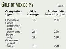
Based on this analysis, the study modeled different completions by using different skin values (Table 1).
The undamaged-well productivity index is 342 bo/d/psi.
The study performed a nodal analysis for a 200 psia THP with the revised Beggs and Brill flow correlation. The oil production rate ranges from 29,975 bo/d (screen only) to 30,035 bo/d (openhole).
The 0 skin damage produces 30,105 bo/d. This implies that the completion does not play a significant role. Even the removal of the mud drilling damage will not represent significant benefits.
These production rates agree with the rates reported for the Ram-Powell field.14 If one replaced the top 51/2-in. tubing with a 7-in, 23 lb/ft tubing, the nodal analysis shows an increase to 35,400 from 30,000 bo/d.
This shows that typical gulf reservoirs depend much more on tubing design than completion type.
The numerical reservoir modeling considered a 61/8-in. hole with 41/2-in. screens for both the multilateral and single horizontal well. Each branch had a 2,000-ft length. Fig. 5 shows the flow rates.
The initial 30,000 bo/d verifies the values reported for the Ram-Powell field. The single horizontal productivity is not affected by the type of completion.
The cumulative production for an openhole gravel pack and screen-only gave similar results. The Level 6 well outperforms the horizontal well production with an extra 7% recovery after 5 years.
North Sea
The parameters15 used for modeling a North Sea reservoir were 27% porosity, 8% Swi, 2,000 md kx and ky, 0.1 kv/kh, 7,500 ft to top of reservoir, 7,570-ft water-oil contact, 70-ft oil column, 3,150 psia initial pressure, 155° F., Level 6 junction at 7,171-ft TVD (7,733-ft MD), 3,000-6,000 ft of horizontal completion at 7,525 ft TVD (11,520-14,520- ft TD), 300 scf/bbl solution GOR, 29° oil gravity, 0.8 gas gravity, 1,873 psia pb, 1.86 viscosity at pi, and 3.3.10–6 psi–1 cf.
The hole size is 81/2-in. for the horizontal well and 133/8-in. Level 6, and 61/8 in. for the 95/8-in. Level 6 junction. For 81/2-in. hole the completion is screen-alone with a total skin of 33. In all cases the production tubing is 7-in. OD (6.3-in. ID).
The study modeled this case as natural flow with a constant THP of 200 psia with a simulated single 6,000-ft horizontal. For the multilateral, the study looked at both 3,000 and 6,000-ft branches.
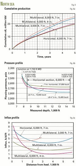
Fig. 6a shows that the multilateral completions outperform the singe-horizontal completion. Water encroachment is the main contributing factor for the different performance. The water production from the 6,000-ft horizontal well is significantly greater than the 6,000-ft Level 6 wells (20% vs. 1% watercut after 1 year).
In the case of two 3,000-ft branches, the water production is similar to that of the single horizontal well. This implies that reservoir contact is important in water control in high productivity reservoirs.
The 3k-1k-3k Level 6 produces 2% more oil than the 6,000-ft horizontal, the 6k-1k-6k 95/8-in. Level 6 produces 22% more oil than the single horizontal (26.3 vs. 21.5 million bbl), and the 133/8-in. Level 6 produces 28% extra (27.5 vs. 21.5 million bbl). In this case, one could replace the 133/8-in. Level 6 with a 95/8-in. Level 3 if the well did not require hydraulic isolation.
Fig. 6b shows the friction pressure along the horizontal section for the 95/8-in. Level 6 is 175 psi. Both the single horizontal and the 133/8-in. junction with 65/8-in. screen generate a 50 psia friction drop.
Fig. 6c indicate that the high friction losses for the 95/8-in. junction generate a preferential influx at the heel position. For the other configurations the influx profile is more uniform. The drawdown profile shows similar trends to the oil influx profile with values ranging from 140 psia at the heel to 25 psia at the toe for the 6k-1k-6k 95/8-in. Level 6.
Middle East
The parameters15 used to model a Middle East well are 26% porosity, 10% Swi, 6,000 md kx and ky, 0.1 kv/kh, 7,100-ft to top of reservoir, 7,280-ft water-oil contact, 180-ft oil column, 2,650 psia pi, 160° F. reservoir temperature, Level 6 junction at 6,796-ft TVD (7,358-ft MD), 2,000-ft of horizontal completion at 7,150-ft TVD (10,145-ft TD), 200 scf/bbl solution GOR, 32° oil gravity, 0.8 gas gravity, 990 psia pb; 1.62 cp viscosity at pi, and 3.3.10–6 psi–1 cf.
The hole size is 81/2-in. for the horizontal well and 133/8-in. Level 6, and 61/8 in. for the 95/8-in. Level 6 junction.
For the 81/2-in. hole the completion is screen-alone with a total skin of 28. In all cases, the production tubing is 41/2-in. OD (3.93-in. ID).
This reservoir was modeled as natural flow with a constant 200 psi THP. The study simulated a single 2,000-ft horizontal length.
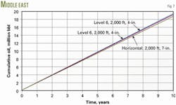
The initial production rates are about 6,000 bo/d (Fig. 7).
The 95/8-in. Level 6 produces 3% more oil than the single horizontal (19.3 vs. 18.8 million bbl), whereas the 133/8-in. Level 6 produces 4% extra (19.5 vs. 18.8 million bbl).
The multilateral does not have much friction advantage because of the subnormal pressure that generates lower than normal production rates in natural flow. The extra reservoir contacted by the multilateral well does not generate significant gain over the conventional horizontal due to the high permeability and low viscosity characteristics of this reservoir.
Water influx control
The study used published information for the Harding field in the North Sea to investigate the potential benefits of multilateral wells for water influx minimization.18-20
Parameters used were 34% porosity, 20% Swi, 10,000 md kx and ky, 0.1 kv/kh 5,500 to top of reservoir, 5,682-ft water-oil contact, 182-ft oil column, 2,400 psia pi, 140° F. reservoir temperature, Level 6 junction at 5,211-ft TVD (5,773-ft MD), 2,000-ft of horizontal completion at 5,565 TVD (8,560-ft TD), 275 scf/bbl solution GOR, 20° oil gravity, 0.7 gas gravity, 2,049 pb, 4.9 cp viscosity at pi, 3.3.10–6 psi–1 cf.
The study used a constant 10,000 b/d liquid production rate, which may represent the case of artificial lift with electrical submersible pumps, which is a typical design in North Sea reservoirs.
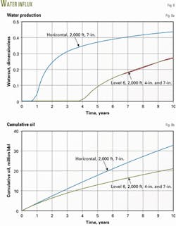
Each branch has a 2,000-ft horizontal section. Figs. 8a and 8b compare single horizontal wells with the 95/8 and 133/8-in. Level 6 junctions.
Water breaks through in the single horizontal during the first year of production. The water breakthrough in the multilateral wells is delayed until the fourth year.
Multilateral wells provide the advantage because of the greater contact area with the reservoir. This generates smaller drawdowns and therefore reduced water influx.
The main benefit is 60% more production from the multilateral after 10 years.
The choice of junction size 95/8 vs. 133/8-in. has no effect on productivity. This also implies that the selection of Level 6 vs. Level 3 is not a production concern in these types of reservoirs.
Figs. 9a and 9b compare the oil saturation profiles after 2 years of production. The water has entered into the single horizontal and is about 30 ft below the well in the multilateral well case.
Intelligent multilaterals
Level 6 multilateral configurations allow the installation of flow-control valves to selectively control flow from lateral branches.
China National Offshore Operating Co. (CNOOC) in November 2002 drilled and completed the world's first intelligent Level 6 multilateral with flow control for each branch in the Java Sea, Indonesia.21
BP PLC completed an extended reach dual-lateral in Europe with downhole valves. Three hydraulically controlled valves controlled the influx from each lateral independently to minimize water production and optimize electrical submersible lift.5
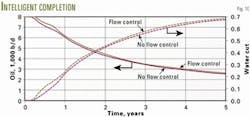
The study used two regions to model the potential benefits of intelligent multilateral wells. One branch was positioned 100 ft above the water zone and the second branch is placed 140 ft above the contact.
One downhole valve at the junction position controls the water production from the branch closest to the water contact. The well was produced at a constant 8,000 b/d liquid rate.
Fig. 10 shows that the controlled case results in only a small amount of incremental production. The increased cumulative oil after 5 years is 2%.
While the downhole valve may effectively reduce the water cut in one of the branches, the pressure drop imposed across the valve also tends to reduce the total oil production, therefore significant production gains are not observed.
In a single branch North Sea application, this completion considerably reduced the GOR water cut but also reduced the oil rate.12
Implementation of intelligent completions has to consider other aspects such as the economic impact of excessive water or gas production.
Study results
The 133/8-in. Level 6 has an advantage over the 95/8-in. junction for high-productivity wells mainly because of friction. In low-productivity wells, the difference in production is not substantial.
For horizontal sections with high productivity indexes, the effect of completion is negligible. Openhole, screen-alone, cased-perforated, and openhole gravel pack completions yield similar productivities. This is due to moderate skin damage, which has negligible effects on productivity.
In general, multilateral wells perform better than single horizontal wells. The best technology to use depends on economic considerations. Considering the extra cost involved, multilateral technology starts to become attractive for incremental production of 10% or more.
Most offshore reservoirs studied have high permeability. During the early life of many of these high productivity wells flow naturally. Properly evaluation of these wells requires rigorous reservoir-surface modeling.
Two attractive features of multilateral technology for offshore applications are slot conservation and reduction of water production. For unfavorable oil mobility (intermediate gravities of about 20°), multilateral wells represent a strong advantage over single horizontal wells.
Multilateral technology is very attractive for heavy oil applications. The incremental production over single horizontal wells is in general greater than 70%. This advantage is because multilaterals provide greater reservoir contact in low-productivity reservoirs.
Acknowledgments
The authors express their gratitude to the management of Schlumberger for sponsoring this study and permission to publish this paper. F
References
1. Berge, F., and Hepburn, N., "A New Generation Multilateral System for the Troll Olje Field-Development and Case History," Paper No. SPE 71837, SPE Offshore European Oil and Gas Conference, Aberdeen, Sept. 4-7, 2001.
2. Stalder, J.L. et al., "Multilateral-Horizontal Wells Increase Rate and Lower Cost Per Barrel in the Zuata Field, Faja, Venezuela," Paper No. SPE 69700, SPE International Thermal Operations and Heavy Oil Symposium, Margarita Island, Venezuela, Mar. 12-14, 2001.
3. Al-Azkawi, A., et al., "Multilateral Wells Improve Development of Heavy Crude Production in the Mukhaizna Field, Sultanate of Oman," Paper No. SPE/PS-CIM/CHOA 79021 International Thermal Operations and Heavy Oil Symposium and International Well Technology Conference, Calgary, Nov. 4-7, 2002.
4. Al-Umair, N.A., "The First Multilateral/Dual Completion Well in Saudi Arabia," Paper No. IADC/SPE 62771, IADC/SPE Asia Pacific Drilling Technology, Kuala Lumpur, Sept. 11-13, 2000.
5. Lucas, C., et al., "Near-Wellbore Modeling to Assist Operation of an Intelligent Multilateral Well in the Sherwood Formation," Paper No. SPE 71828, SPE Offshore European Oil and Gas Conference, Aberdeen, Sept. 4-7, 2001.
6. Salas, J.R., et al., "Multilateral Well Performance Prediction," Paper No. SPE 35711, SPE Western Regional Meeting, Anchorage, May 22-24, 1996.
7. Zhu, D., et al., "Evaluation of Crossflow Effects in Multilateral Wells," Paper No. SPE 75250, SPE/DOE Improved Oil Recovery Symposium, Tulsa, Apr. 13-17, 2002.
8. Rivera, N., et al., "Application of Multilateral Wells in Solution Gas-Drive Reservoirs," Paper No. SPE 74377, SPE International Conference and Exhibition, Villahermaosa, Mexico, Feb. 10-12, 2002.
9. Renard, G., et al., "Potential of Multilateral Wells in Water Coning Situations," Paper No. SPE 39071, Fifth Latin American and Caribbean Petroleum Engineering Conference and Exhibition, Rio de Janeiro, Aug. 30-Sept. 3, 1997.
10. Sinha, S., Vega, L., Kumar, R., and Jalali, Y., "Flow Equilibration Toward Horizontal Wells Using Downhole Valves. A Single Well Study on Dual Drive," paper SPE 68635 presented at the 2001 Asia Pacific Oil and Gas Conference and Exhibition, Jakarta, Indonesia, Apr. 17-19.
11. Yeten, B., et al., "Optimization of Smart Well Control," Paper No. SPE/PS-CIM/CHOA 79031, International Thermal Operations and Heavy Oil Symposium and International Well Technology Conference, Calgary, Nov. 4-7, 2002.
12. Rundgren, G., et al., "Installation of Advanced Completions in the Oseberg 30/9-B-38 B Well," Paper No. SPE 71677, SPE Annual Technical Conference and Exhibition, New Orleans, Sept. 30-Oct. 3, 2001.
13. Boardman, D.W., et al., "Evaluation of production methods in the Morichal heavy oil reservoirs," Paper No. SPE 53691, SPE Latin American and Caribbean Petroleum Conference, Caracas, Apr. 21-23, 1999.
14. Lester, G.S., et al., "Ram/Powell Deepwater Tension-Leg Platform: Horizontal-Well Design and Operational Experience," SPE Drilling and Completion, June 2001, pp. 117-26.
15. Rivera, N., "Offshore and heavy oil development by horizontal and multilateral well application, final report," Schlumberger, College Station, Tex., Summer 2002.
16. Joshi, S.D., Horizontal Well Technology, PennWell Corp., Tulsa, 1991.
17. Foster, J., et al., "The Evolution of Horizontal Completion Techniques for the Gulf of Mexico. Where Have We Been and Where Are We Going!," Paper No. SPE 53926, SPE Latin American and Caribbean Petroleum Conference, Caracas, Apr. 21-23, 1999.
18. Smith, S.L., "The Harding Field: A Low Development Cost per Barrel Concept Becomes a Reality," Paper No. SPE 30384, Offshore Europe Conference, Aberdeen, Sept. 5-8, 1995.
19. McKay, G., et al., "Harding A Field Case Study: Sand Control Strategy for Ultra High Productivity and Injectivity Wells," Paper No. SPE 48977, SPE Annual Technical Conference and Exhibition, New Orleans, Sept. 27-30 1998.
20. Jayasekera, A.J., and Goodyear, S.G., "The Development of Heavy Oil Fields in the U.K. Continental Shelf: Past, Present and Future," Paper No. SPE 54623, SPE Western Regional Meeting, Anchorage, May 26-28, 1999.
21. Fraija, J., et al., "New Aspects of Multilateral Well Construction," Oilfield Review, Autumn 2002.
Based on a presentation to PennWell's High-Tech Well conference, Galveston, Feb. 11-13, 2003.
The authors
Nestor Rivera is a petroleum engineer with experience in drilling and completions, and in reservoir engineering and production performance analysis. Rivera currently is a petroleum engineering PhD candidate at Texas A&M University. Rivera has a BS from Universidad de Santander and an MS from the University of Texas, both in petroleum engineering.
Baljit S. Sehbi is senior reservoir engineer with Schlumberger Consulting Services in College Station, Tex. He has experience in reservoir engineering and formation evaluation by wireline, well testing, and pressure-transient analysis. Shebi holds an MS in petroleum engineering from Texas Tech University.
John P. Spivey is principal reservoir engineer with Schlumberger Consulting Services in College Station, Tex. His experience includes pressure-transient testing, reservoir engineering, continuing education, and software development. Spivey has a BS from Abilene Christian University, an MS from University of Washington, and a PhD in petroleum engineering from Texas A&M University.
Jim Fairbairn is the global manager for the multilateral business of Schlumberger. He previously worked for Occidental Petroleum Corp. and Conoco Inc. in various management positions. Fairburn holds a BS in petroleum engineering from Louisiana Tech University.
