Special Report: Integrity-verification methods support US efforts in pipeline safety
The US pipeline industry, undergoing significant changes because of revisions to safety regulations, has responded by developing standards, recommended practices, and guidelines that can be used by operators to develop, implement, and validate pipeline-integrity verification programs.
Methods for verifying pipeline integrity include pressure testing, in-line inspection, and others, such as direct assessment, that can be demonstrated to be equivalent. Each of these techniques has unique capabilities and limitations that need to be considered in developing and validating an integrity program.
Technical societies and industry groups within the pipeline industry have developed numerous references that are available.
Revisions
The US Department of Transportation (DOT) Office of Pipeline Safety (OPS) is making significant revisions to pipeline safety regulations. These changes have focused on the 160,000 miles of federally regulated liquid pipelines and 330,000 miles of natural gas transmission and gathering pipelines all in high-consequence areas (HCAs).
Although the pipeline industry has an excellent safety record and pipelines are undoubtedly the safest mode for transporting hydrocarbons, these expanded regulatory requirements will further decrease the likelihood of failures that could affect the general public and the environment.
These new regulations have prompted development of many standards, recommended practices, and guidelines that can be used by operators to develop, implement, and validate pipeline-integrity verification programs. Many of the technical societies and industry groups, including NACE International, the American Society of Mechanical Engineers (ASME), the American Petroleum Institute (API), and the Gas Technology Institute (GTI), have supported development of these references.
This article looks at recently enacted and pending regulatory requirements and at methods for integrity verification by pipeline operators.
Regulatory requirements
For operators of gas transmission pipelines, DOT on Jan. 9, 2002, issued a Notice of Proposed Rule Making for defining HCAs under 49 CFR Part 192.761.1 This notice defines an HCA based upon class locations (Classes 3 and 4) and proximity to highly populated areas such as schools and hospitals.
Details for the remainder of the "Integrity Management of Pipelines" ruling for gas operators have yet to be published, however.
In anticipation of the new ruling, ASME has published B31.8S, a supplement to its standard B31.8, that outlines the technical requirements for implementing elements of an integrity-management program, as well as guidance in developing the specific integrity management plan.2
The final rule for hazardous liquids pipelines, dated Jan. 16, 2002, requires that all operators of hazardous liquid pipelines, regardless of mileage operated, develop and implement a written integrity-management program by specified dates.1 This rule requires the continual integrity assessment of all pipeline segments that could affect an HCA.
The definition of an HCA for hazardous liquid pipelines is complex. It considers such areas as unusually sensitive areas, highly populated areas, and commercially navigable waterways that could be affected by a product release.
The process of defining HCAs requires operators to assess the risk that a particular pipeline segment or pipeline facility may leak or rupture. The integrity threats that should be considered have been classified as time dependent (corrosion and stress corrosion cracking, or SCC), time independent (third-party damage, natural forces), and stable (pipe manufacturing defects).
The identification of HCAs has been facilitated by OPS's National Pipeline Mapping System. Guidance on clearly identifying HCAs has, however, been left to the operator and requires volumes of data to be assembled and assessed. Further guidance has been provided to liquid operators with the publication of API Standard 1160.3
The liquid rule has identified clear timelines for completing the initial assessment, on-going reassessments, and specified timescales for responding to in-line inspection results: immediate excavations, 60-day excavations, and 180-day excavations.
Risk assessment and prioritization are the foundations of the new integrity-management requirements in which segments with the highest perceived risk factor should be assessed first.
Methods for assessing the integrity of pipeline include in-line inspection (ILI) tools, pressure testing, or other technologies (direct assessment, for example) that the operator demonstrates can provide the equivalent of either in-line inspection or pressure testing. If another technology is chosen, the operator is required to notify OPS. The new ruling does not specify the methods to be used for facilities.
Verifying integrity with these tools requires a detailed knowledge of the capabilities, benefits, and limitations of the different methods and when to employ a combination of methods to address particular integrity threats.
The primary methods for pipeline operators to verify the integrity of a pipeline system include direct assessment, pressure testing, and in-line inspection. Each of these has capabilities and limitations to be considered during evaluation of a pipeline system.
Following is a discussion on the status, capabilities, benefits, and limitations of each verification method.
Direct assessment
Formalized processes to assess the condition of pipelines with respect to external corrosion (EC), internal corrosion (IC), and SCC are in various phases of development. The overall approach is termed "direct assessment" (DA), and the three forms of corrosion DA are ECDA, ICDA, and SCCDA.
When applied consistently and in compliance with evolving industry standards, DA will improve the overall safety, integrity, and reliability of the pipeline infrastructure.
NACE International standards will detail all the corrosion direct-assessment methods. The ECDA Recommended Practice is complete, and standards for ICDA and SCCDA are under development within NACE task groups. In addition, an abridged version of direct assessment can be found within ASME B31.8S.2
Each of the direct-assessment methods addresses certain kinds of pipelines, and efforts are under way to broaden the application of the methods.
•ECDA addresses buried onshore pipelines. Offshore pipelines are excluded because of the difficulty in performing electrical surveys and direct examinations on a subsea pipeline.
•ICDA at present addresses gas transmission lines with nominally dry gas, but an approach for wet gas and possibly liquid lines may be developed in the future. ICDA for gas transmission lines was developed first because pipelines crossing HCAs typically carry nominally dry gas, failures have recently occurred in these systems, and a concept for developing the approach existed.
•SCCDA is applicable to the external surface of onshore pipelines and is in the earliest stage of development. This is in part because of the lower number of failures attributed to SCC as compared to internal and external corrosion.
Even though SCCDA could be considered a part of ECDA, the methods for identifying susceptibility to corrosion and SCC differ, justifying an independent approach.
Direct-assessment methods do not depend on the ability of a pipeline to be pigged, making them most valuable to those pipelines that cannot accept pigs. A survey by the US Interstate Natural Gas Association of America determined that only 35% of interstate natural gas transmission pipelines are piggable and 43% are either unpiggable or would require extensive modification such as replacing bends.4
For intrastate pipelines, the fraction of unpiggable pipelines increases. For example, the New York Gas Group, the state's gas utility trade association, has estimated that about 75% of pipelines that operate at stresses greater than 20% specified minimum yield stress (SMYS) within New York are unpiggable.
Although direct assessment can be used to enhance pipeline integrity management for a significant portion of unpiggable lines, one outcome may be prioritizing a pipeline of interest for mechanical modifications so that an in-line inspection (ILI) tool may be run.
A technical advantage is that direct-assessment methods detect anomalies based on the causes of corrosion and therefore have the ability efficiently to detect the most likely locations of present and future corrosion. This broadens an integrity-management perspective from detection and repair to include prevention and mitigation.
External-corrosion DA
Because details of ECDA are in a NACE Recommended Practice,5 only an overview and brief discussion will be provided here.
Pipeline operators have historically used a variety of electrical survey tools to manage external corrosion, and ECDA incorporates these tools in a formal process containing four steps:
The tools include DC and AC methods.
DC methods include measuring the level of cathodic polarization on the pipe (close-interval survey) and measuring voltage gradients associated with cathodic current through the soil (or, DCVG).
AC methods are performed by application of a source of AC current of specific frequency allowing it to be discriminated from background DC current (or AC current with different frequency). Magnetometers measure the amount of current attenuation along the pipe, and current loss is attributed to coating defects.
Detecting areas of AC voltage gradient (or, ACVG) can serve as a method to detect local coating defects.
Direct examinations are performed at locations most likely to contain an anomaly. This step includes prioritization of indications from indirect inspections, excavating locations where coating and corrosion activity are most likely, measuring coating damage and corrosion defects, evaluating damage severity, root-cause analysis, and a process evaluation.- Post assessment defines reassessment intervals and assesses the overall effectiveness of the ECDA process.
The list of available indirect-inspection methods shows that all of the tools rely on current conducting through the pipe wall, across the bare-metal/soil interface, and through the soil.
The voltage, or potential, of the pipe vs. a reference electrode (for close-interval survey) is measured with a voltmeter that relies on a small amount of current passing from the pipe to the surrounding soil, that is, across the bare-pipe/soil interface.
DCVG and ACVG detect locations where current concentrates to pass across the bare-pipe/soil interface. AC current attenuation occurs because areas of bare metal allow current to pass.
One limitation of indirect inspection methods, therefore, is the inability to detect corrosion in locations where current is shielded (under some types of disbonded coatings, for example) or when other sources of bare metal exist (as in direct bonded anodes). For pipelines where these problems exist, either ECDA cannot be used, or other methods should be used to compensate.
For example, the use of buried CP coupons to measure accurate potentials or the use of a disbonded coating coupon (under development by at least two organizations) may provide sufficient additional information to broaden the applicability of ECDA.6-8
Internal corrosion DA
ICDA for gas transmission lines enhances the assessment of internal corrosion in pipelines and is based on the principle that corrosion is most likely where water first accumulates.9 The method is applicable to gas transmission pipelines that normally carry dry gas but may suffer from short-term upsets of wet gas or liquid water (or other electrolyte).
Detailed examination of locations along a pipeline where an electrolyte such as water first accumulates provides information about the remaining length of pipe. If the locations along a length of pipe most likely to accumulate electrolyte have not corroded, then other locations less likely to accumulate electrolyte are unlikely to have suffered corrosion.
ICDA incorporates all existing methods of examination available to a pipeline operator.
The procedure mimics the four-step process originally developed for ECDA:
Preassessment includes collection of historic and current data to determine whether ICDA is feasible and defines regions of assessment.The data to be collected are typically available in construction records, operating and maintenance histories, alignment sheets, elevation maps with depth of cover, inspection records, and inspection reports from previous integrity evaluations or maintenance actions.
Feasibility of ICDA of gas transmission lines is determined by a set of pipeline characteristics on which ICDA development was based. The first characteristic is that the transported gas is normally dry (<7 lb/MMcf or 112 g/cu m) and any short upsets of water eventually vaporize into the gas phase.
Other characteristics include the absence of corrosion inhibitors, lack of protective coatings, and infrequent (or no) cleaning using a pig. Water is the primary source of corrosive electrolyte.
Flow-modeling predicts the locations most likely to have suffered corrosion, those that first collect water.Stratified film flow is considered the primary liquid-water transport mechanism, and any liquid droplets possibly entrained in the gas will evaporate because gas transmission pipelines carry nominally dry gas most of the time.
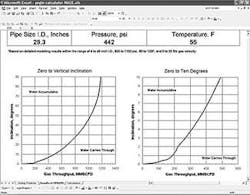
Film flow along a pipe is driven by the forces of shear stress imposed by the moving gas and gravity determined by pipe inclination. Results of multiphase flow modeling predict the critical angle of inclination that would hold up water.
A simple spreadsheet (Fig. 1) calculates the critical angle vs. gas velocity, given pipe diameter, pressure, and temperature.
Selecting sites for excavations and detailed examination to detect internal corrosion may include many techniques, but excavation and inspection by radiography or ultrasonic WT measurement will be the most commonly used methods.There may also be some applications in which the most cost-effective approach is to run an in-line inspection tool for a portion of pipe and use the results to assess the downstream internal corrosion where a pig cannot be run.
The inclination profile of a pipeline is determined and compared to the critical angle for liquid accumulation (Fig. 2). The first location (moving downstream) with inclination greater than the critical angle is the first inspection point.
Absence of corrosion at the target location indicates that downstream corrosion is unlikely. If a range of velocities or other relevant parameters exists, however, so that the critical angle for accumulation may be smaller at certain times, upstream integrity cannot be determined by examination of a downstream inclination.
An iterative approach is used to assess the upstream portion of pipe starting with the highest upstream inclination angle, which is less than the critical value.
If the locations most susceptible to corrosion are free of damage, the integrity of a large portion of pipeline mileage has been ensured and resources can focus on pipelines in which corrosion is more likely. Of course, the presence of corrosion indicates a potential integrity problem, and the method is also considered successful.
- Post assessment covers analyses of data collected from the previous three steps to assess the effectiveness of the direct-assessment process and determines reassessment intervals.
SCC direct assessment
SCC is the slow crack growth of a normally ductile material in a corrosive environment. It is caused by the simultaneous presence of a susceptible alloy, a tensile stress, and a specific corrosive medium.
In the case of SCC of underground pipelines, residual pipe stresses and internal pressurization provide the tensile stress. Groundwater, which migrates beneath a disbonded coating and is altered, in some instances, by the cathodic-protection system, is the specific corrosion medium.
The purposes of an SCCDA program are to determine whether a pipeline system is susceptible to SCC, determine whether the cracking is significant and extensive, and prioritize the system for ILI, hydrostatic testing, or other forms of remediation.
Canada's National Energy Board has developed a very specific definition of "significant" in terms of the length of interlinked cracks found on the pipe that are deeper than 10% WT. It is the length (regardless of the actual depth) of a 50% through-wall flaw that would fail at 110% SMYS. Significant cracking is extensive if the locations are numerous and not considered unique in some way.
NACE International is undertaking development of the formalized SCCDA process. Similar to ECDA and ICDA, there are four program components: pre-assessment, indirect inspections, direct examinations, and post assessment.
This document should be completed in 2004.
Hydrostatic testing
US federal safety regulations (CFR Part 192 Subpart J and CFR Part 195 Subpart E) require pipelines that operate at pressures at or greater than 30% of SMYS and transport natural gas or hazardous liquids be pressure tested at a pressure equal to 125% of the maximum allowable operating pressure (MAOP) following construction or replacement.
Periodic hydrostatic testing also is a common method used to ensure the integrity of operating pipelines that contain time-dependent defects, such as general or pitting corrosion, fatigue, corrosion fatigue, or SCC. The testing protocol varies for different pipeline operators, depending on details of the system, but most meet the minimum federal requirements for new construction.
Typically, a desired pressure range is established, with the minimum pressure selected to ensure integrity and the maximum test pressure designed to minimize failure of noninjurious features, such as stable weld flaws, in the pipeline. Factors considered in the selection of a minimum pressure include the estimated population of defects in the pipeline, the estimated growth rate of these defects, and the MAOP of the pipeline.
If there are a large number of slowgrowing defects and the MAOP of the pipeline is relatively low, it may be desirable to establish a low minimum test pressure to avoid a large number of hydrostatic test failures. On the other hand, a higher minimum test pressure is needed to avoid frequent retesting for fast-growing defects and high operating pressures.
Some pipeline companies use a short duration high-pressure spike (100 to 110% of SMYS for 1 hr, for example) to remove long flaws capable of producing ruptures, followed by a long duration low-pressure test (90% of SMYS for 24 hr, for example) to locate leaks in the pipeline.
The most significant benefit of hydrostatic testing is that it will remove all axial defects, regardless of geometry, that have critical dimensions at the test pressure. In the case of ILI and other integrity programs, such as ECDA, there is a finite probability that a near-critical defect will be missed by the assessment method.
In the case of crack-like defects, such as fatigue cracks and stress corrosion cracks, hydrostatic testing also will blunt and impart a compressive residual stress at the crack tip of larger sub-critical defects that remain in the pipeline following testing. The blunting and compressive residual stresses will inhibit subsequent crack growth.
There are a number of significant limitations with hydrostatic testing. It is not feasible for pipelines that cannot be taken out of service, including most pipelines that are not looped. It is expensive, estimated to cost from $1,250 to $5,000/mile to prepare a pipeline for testing and $2,000/mile to conduct the testing for a 16-in. to 24-in. OD pipeline, including water-handling costs.
Loss of throughput is the largest cost component of hydrostatic testing and ranges from $7,000/mile for a 24-in. gas pipeline up to $90,000 for a 16-in. liquid petroleum pipeline.10
Hydrostatic testing typically removes very few flaws in a pipeline, in comparison with ILI or direct assessment, where many subcritical flaws are either removed or repaired. It provides no information on the condition of the pipeline other than for those flaws that fail.
For older pipelines and those containing low-frequency electric resistance welded (ERW) longitudinal seams, high-pressure tests (greater than 100% SMYS) may not be practicable because the testing will fail large numbers of noninjurious weld flaws. With lower pressure tests, the hydrostatic retest period may be so short as to make hydrostatic testing impracticable.
Fig. 3 shows the remaining life as a function of test pressure for a flaw in a 24 in., 0.250-in. WT API 5L X-52 pipeline operating at 72% SMYS, with a 6-in. flaw and an assumed flaw growth rate of 0.012 in./year (0.3 mm/year).
This is a typical upper-bound growth rate for active corrosion defects. In this example, the retest frequency would have to be less than 5 years for a hydrotest at 90% SMYS to avoid further failures of the pipeline
Hydrostatic testing is ineffective against circumferential flaws because the maximum axial stress produced by internal pressurization is only half the circumferential stress. While hydrostatic testing is capable of locating leaks, it is ineffective in removing short flaws that ultimately will produce leaks. Leaks can occur shortly after a hydrostatically tested line has been returned to service.
Finally, hydrostatic testing can cause tearing of subcritical flaws. This can lead to a phenomenon known as "pressure reversals," in which the pipeline fails at a lower pressure in a subsequent pressure test. Typically, the amount of tearing and the magnitude of these pressure reversals are small, but, in rare circumstances, large pressure reversals, exceeding 100 psig, can occur.
In-line inspection
In-line inspection (ILI) is a pipeline-integrity verification method used to identify and characterize metal loss, deformation, crack-like features, pipeline movement, and positioning by use of a nondestructive testing tool traveling inside the pipeline.
Industry practices
A number of industry practices that address in-line inspection programs have been developed; a few are included in the following:
•"Specifications and Requirements for Intelligent Pig Inspection of Pipelines," published in 1998 by Shell Exploration and Production in the Netherlands, resulted from work by an industry group called the Pipeline Operators Forum (POF).
This specification defines anomaly types by length and width, requires ILI vendors to specify probability of detection (POD) and identification (POI), and specifies the content of a Final Inspection Report.
•"In-Line Nondestructive Inspection of Pipelines – Publication 35100," published December 2000 by NACE International, provides a conceptual approach for different types of in-line inspection tools, costs-benefits analysis, piggability of pipelines, preparation of the inspection, and analysis of results.
•"In-Line Inspection Recommended Practice - RP-0102-2002," published February 2002 by NACE International, describes the criteria and processes for planning, implementing, and managing in-line inspection programs including in-line inspection tool data-acceptance criteria and guidelines for data management.
This Recommended Practice is currently undergoing revision to include a better definition of ILI process flow and control. Publication is likely in 2003.
•"In-Line Inspection System Qualification Standard - API 1163," currently under development by an API task force, is intended to provide a performance-based guide for in-line inspection systems in processes such as selection and performance validation. Publication will be in 2004.
A standard for ILI personnel qualification, also under development, will define levels of qualification required by ILI-vendor personnel who perform specific tasks (operating an ILI tool, analyzing data, for examples). This standard will be published by the American Society of Non-destructive Testing (ASNT) in early 2004.
ILI technologies
Different ILI technologies are available to the operator depending on the nature of the integrity threat being evaluated. A wider range of technologies is more readily available to liquid operators than gas operators.
Once the in-line inspection method has been selected to assess the integrity of a pipeline, technical specifications should be prepared for feature detection, sizing, and confidence levels. Inspection requirements should focus on expected results considering, but not limited to, commercially available technology.
Pipeline operators are playing a key role in determining the pipeline industry's needs in conjunction with the in-line inspection industry that continually develops and improves its own capabilities to meet the challenges of better detection, classification, sizing, and anomaly location.
Pipeline operators need to inspect for anomalies in the pipe body, at manufactured and field welds, and to identify other characteristics such as pipeline plan, profile, and positioning. Current ILI technology and those under development fall into categories defined by the primary inspection objective: corrosion-caused metal loss, deformation, crack-like or linear-indication, or movement and pipeline mapping.
•Metal-loss technology. Metal loss in-line inspection technology detects, characterizes, and sizes corrosion-caused features. Depending on the type of technology, other types of anomalies can be reported such as manufacturing related features, weld-deposition repairs, arc burns, mechanical damage, dents, wrinkles, laminations, and hydrogen induced cracking. The detection of girth-weld anomalies, including cracking, is also possible.
The current technologies for metal-loss inspections are magnetic-flux leakage (MFL) and ultrasonic (UT) WT measurement. MFL technology can be applied axially or circumferentially.
The metal-loss tools currently available are not capable of characterizing metal loss associated with previous third-party damage. Queen's University, Ontario, in research funded by the Gas Technology Institute, PII North America Inc., and the Natural Sciences & Engineering Research Council of Canada, has been working on detection of mechanical damage with MFL technology.
Results to date indicate that shallow damage geometries are identifiable by MFL technology due to the local residual stress pattern. For large-damage geometries, the MFL signal would follow the usual deformation pattern.11
•Deformation technology. Deformation ILI technology detects and characterizes geometry features such as dents, ovality, bending radius, buckles, wrinkles, and pipe WT transitions. Deformation tools are also used as a preliminary check for bore restrictions for other ILI tools. The current technologies available for deformation ILI are based on electromechanical fingers or eddy-current sensors.
•Crack technology. Crack-like ILI technology detects and characterizes axially orientated cracking such as SCC, whether in the pipe body or seam weld toe, fatigue cracking along the seam weld, and manufacturing-related cracks or crack-like indications such as lack of fusion, hook cracks, or shrinkage cracks.
There are currently four types of crack-tool technology in use and under development: ultrasonic crack detection, elastic wave, circumferentially applied MFL, and electro magnetic acoustic transducer (EMAT).
The latter technology is still under development and has not been used in an operating pipeline. The selection of a specific tool depends on the specific cracking mechanism under investigation.
•Movement and pipeline mapping. The movement and pipeline mapping in-line inspection technology specifically detects and characterizes strains, curvature, and pipeline positioning in terms of northing, easting, and elevation. If multiple runs are available, a positioning differential can monitor pipeline displacement.
The technology is based on inertial systems providing angular and acceleration values over time, which can be transformed to relative position and Universal Transverse Mercator (UTM) coordinates.
Technical phases
ASME B31.8S states that "The effectiveness of the in-line inspection tool used depends on the condition of the specific pipeline section to be inspected and how well the tool matches the requirements set by the inspection objectives."
Consequently, following are some of the recommended high-level technical phases to be developed and implemented in an in-line inspection program:
- Preparation.
- ILI vendor technical evaluations.
- Project management of ILI and excavation programs.
- Development of initial ILI data assessment and excavation program.
- Execution of excavation and repair program.
- Final ILI data assessment and development of long-term maintenance program.
Acknowledgment
The authors acknowledge the assistance of Martin Phillips, Daniel Soenjoto, and Rafael Mora, all of CC Technologies.
References
- Code of Federal Regulations, 49 CFR Parts 186 to 199.
- ASME B31.8 - Managing System Integrity of Gas Pipelines, American Society of Mechanical Engineers, B31.8S, 2001.
- API 1160 - Managing Pipeline System Integrity, American Petroleum Institute, Product No. D11601.
- Selig, B., Clark, E.B., and Hereth, M., "Natural Gas Transmission Pipelines; Pipeline Integrity; Prevention, Detection & Repair Practices," 2000, GRI-00-0193, Gas Research Institute, Chicago.
- NACE Recommended Practice on Pipeline External Corrosion Direct Assessment Methodology, 2000, NACE International, Houston.
- "Technical Report on the Application and Interpretation of Data from External Coupons used in the Evaluation of Cathodically Protected Metallic Structures," NACE International, Publication 35201, February 2001.
- Sridhar, N., Dunn, D., and Moghissi, O., "Disbonded Coating Coupon," International Pipeline Conference, Calgary, Sept. 30- Oct. 4, 2002.
- Moghissi, O., and Lawson, K., "Development of a Disbonded Coating Coupon," Pipeline Research Council International, July 2003.
- Moghissi, O., Norris, L., Dusek, P., and Cookingham, B., "Internal Corrosion Direct Assessment of Gas Transmission Pipelines," CORROSION/2002, Denver, March 2002.
- Koch, G.H., et.al., "Corrosion Costs and Prevention Strategies in the United States," FHWA-RD-10-156, USDOT, March 2002.
- Clapham, L., Atherton, D., Babbar, V., and Rahim, T., "Detection of Mechanical Damage Using the Magnetic Flux Leakage Technique," International Pipeline Conference, Calgary, Sept. 30- Oct. 4, 2002.
The authors
Patrick H. Vieth ([email protected]) is senior vice-president of engineering services for CC Technologies Services Inc. and has provided technical services to the pipeline industry over the past 15 years with particular focus on risk assessment, defect assessment, and in-line inspection programs. Vieth holds a BSc in mechanical engineering from Ohio State University.
Oliver C. Moghissi ([email protected]) is a senior group leader and manager of research for CC Technologies Laboratories Inc.and has 16 years' experience working on corrosion problems as a researcher, oil and gas technical specialist, and university research assistant. Moghissi holds a PhD in chemical engineering from the University of Florida and chairs the NACE International task group responsible for the internal corrosion direct assessment Recommended Practice.
John A. Beavers ([email protected]) is executive vice-president of CC Technologies Laboratories Inc. Over the past 25 years, he has directed and contributed to numerous research programs on corrosion performance of structural materials. Beavers holds a PhD in metallurgical engineering from the University of Illinois and chairs the NACE International task group responsible for the SCC direct-assessment Recommended Practice.
