IMPROVED GAS RECOVERY—1: Maximizing postfrac gas flow rates from conventional, tight reservoirs
Zillur Rahim
Hamoud Al-Anazi
Adnan Al-Kanaan
Saudi Aramco
Riyadh
Hydraulic fracturing technology is widely used to facilitate and enhance the gas recovery process from conventional and tight gas resources.
Part 1 of this two-part article addresses the importance and impact of detailed reservoir characterization and superior stimulation processes on final well performance. Several field examples from Saudi Arabia's gas reservoirs are presented that show the value of effective well planning, reservoir characterization, application of hydraulic fracturing, and proper cleanup.
Part 2 describes optimization of the hydraulic fracturing process. It also illustrates the impact of drilling trajectory and wellbore reservoir connectivity on the proper placement of desired hydraulic fracture treatments and sustained gas production.
Tight gas or unconventional reservoirs that include very low-permeability sandstones, carbonates, or shales cannot be economically produced without hydraulic fracturing. Recently, much progress has taken place in the overall hydraulic fracturing procedures, and the field implementations of advanced stimulation technology have produced good results.
The proper selection of well trajectory, gel concentration, polymer loading, proppant type/size and concentration, perforation methods, locations for packer and frac port placement in a multistage fracturing assembly, number of fracture stages to cover the net pay, etc., have all contributed to successful stimulation and improved gas recovery.
Even though stimulating gas reservoirs has become a routine application and much experience has been gained in this area, not all treatments are straightforward without problems and challenges. Unless a stimulation treatment is carefully designed and implemented, the poststimulation results in moderate to tight reservoirs may not be encouraging and can easily fall below expectation.
The most essential step to close the gap between expected results and actual well performance is to understand the reservoir's characteristics and its potential to produce at a sustained rate after a successful fracturing treatment. Overestimation of reservoir flow capacity and achieved fracture geometry will also overpredict well performance.
Introduction
Unconventional gas resources comprising of tight sand, carbonate, shale, and coal have tremendous hydrocarbon potential. All reservoirs containing conventional gas have very high percentages of unconventional resources that are now being produced or need to be produced in the near future to support world energy.
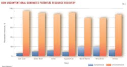
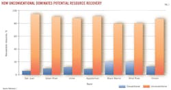
Fig. 1 shows the distribution between conventional and unconventional resources from a few basins in the US indicating huge tight gas potential.1 Fig. 2 is the well-known resource triangle depicting the availability of gas resources associated with some anticipated reservoir flow capacities.2
The unconventional gas portion is huge with a total of 32,600 tcf of gas in place (GIP) and 7,400 tcf only in tight sand estimated across the world.
Saudi Arabia is embarking on tapping into its tight sand and shale resources. Along with citing examples from conventional reservoirs, the article also focuses on tight gas reservoirs, deployment of new technology, and making realistic estimates of well deliverability to close the gap between expected production and actual well performance.
Tight gas wells are not expected to produce at a high rate even after stimulation. They also do not clean up fast after a stimulation treatment. The pressure transient tests conducted do not necessarily achieve a pseudosteady-state flow regime due to slowness of fluid movement in low permeability.
To improve the performance of wells drilled in tight gas reservoirs, application of advanced drilling, completion, and stimulation technology is required. Development and production of tight gas are always challenging, and many hurdles are encountered and overcome to achieve success. This article addresses improved well design and fracturing technology in moderate and tight gas reservoirs to realize full well and field potential.
Addressing the challenges
In horizontal as well as in vertical wells, underachieved production performance is not uncommon. Some potential causes for underperforming wells could be:
• Not accounting for reservoir heterogeneity and permeability anisotropy.
• Inefficient perforations to connect wellbore with the reservoir.
• Leftover damage from drill-in fluids that was neither cleaned up nor bypassed by stimulation.
• Ineffective well design.
• Ineffective stimulation treatment.
• Insufficient postfracture cleanup causing fracture conductivity degradation.
Since its inception, hydraulic fracturing has become a strong technical process applied to oil and gas wells to overcome many of the above-mentioned challenges. The primary objective of reservoir stimulation is to attain a sustained higher gas rate in the early part of well life to shorten payout time.
In the case of tight gas reservoirs in carbonates, sandstones, and shale, wells cannot produce at any measurable rate without stimulation. Properly designed and implemented hydraulic fracturing treatments not only bypass wellbore damage but also connect the virgin reservoir with long and highly conductive paths to ensure continuous gas flow into the wellbore.
The fracture conductivity is an essential element to minimize impact due to fluid blockage and produce from high-condensate gas reservoirs.3 Major consideration must be made in selecting correct stimulation fluid chemistry, such that fracture fluid damage is minimized and posttreatment flowback is easily achievable.
A good perforation strategy also adds to the success of stimulation, particularly in deep tight gas formations with high in situ stress, pressure, and temperature.
Jetting and creating slots with the use of acid or very small mesh size proppant in both vertical and horizontal completions, a viable alternative to the conventional charge perforation methods, has shown good results. The extremely high jetting velocity builds an immense pressure on the target interval producing good communication and channeling/cavity of the wellbore with the reservoir. The perforation tunnels also make the subsequent fracturing treatment easier by lowering the near wellbore friction pressure loss.4
The advanced multistage fracturing (MSF) applied to horizontal wells has proven to be a very useful technology. Depending on the well trajectory and azimuth, several fractures can be induced and propped in sequence in selected intervals to augment the flow path between the reservoir and the wellbore.
For horizontal wells, the number of stages in MSF completions depends on reservoir development, stress profile, and wellbore trajectory. When a wellbore is placed along the minimum in situ stress (σmin) direction, the possibility of one induced fracture overlapping another is nearly eliminated. This is because the fracture plane is in the direction of the maximum horizontal in situ stress (σmax), perpendicular to σmin. This means multiple, independent fractures can be placed along the wellbore.
On the contrary, when the well trajectory is in the σmax direction, the created fractures are longitudinal along the wellbore plane, thereby limiting the number of independent fractures that can effectively be created and placed. Considering proper reservoir development and geomechanics, it is prudent to place wellbore trajectory toward σmin to ensure inducing multiple hydraulic fractures.
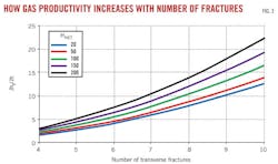
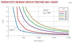
Figs. 3 and 4 show results from analytical solutions of the productivity index (PI) ratio between fractured horizontal wells and unfractured wells as functions of a number of hydraulically created transverse fractures (NFR).5 The solutions also depend on the net pay thickness of the treated interval (HNET or hnet) and the vertical to horizontal permeability ratio (kv/kh) as shown in the figures.
As an example, a horizontal well with net pay thickness of 200 ft can double its productivity ratio with respect to unfractured horizontal well by increasing the number of fractures from 5 to 7 (Fig. 3). Similarly, a horizontal well with 1,000 ft of reservoir contact will have a productivity ratio that is twice that of an unfractured well (Fig. 4). The plots derived from analytical solutions reinforce the need of conducting fracture treatments, even in case of high reservoir contact horizontal wells.
Improved perforation technology
Near-wellbore tortuosity is one of many conditions that can cause additional friction pressure loss during the injection or production phase of a well.3
Tortuosity can be caused from the creation of T-shaped fractures, reoriented fractures, and multiple fractures. Good drilling and perforation practices are essential to minimize such pressure loss and establish good communication between the well and the virgin reservoir.
Regardless of completion configuration, there always needs to be good communication between the wellbore and the formation to ensure full well potential. Such communication is achieved by proper choice and placement of perforations. Two major types of perforation techniques that are widely used by the industry today are provided in the following sections.
Conventional charge perforation (CCP)
In cased-hole completions, shaped explosive perforation charges, also known as CCP, represent the most-used perforation technique in the industry.
CCP generates very high temperature and pressure during the perforation process. This often creates localized stress and can crush cement bonds around perforations between the casing-formation annulus. Also, during perforation, very low permeability crushed zones around the tunnels are created that restrict both injection and production.
Another perforation method is characterized by extreme underbalance, creating a severe pressure drop simultaneous to the discharge of explosives, sometimes used to immediately produce back the damage. The debris is drawn out before it concentrates and solidifies. Such underbalance technologies are usually expensive and therefore prohibitive in routine activities.
For a well that is a fracturing candidate, the near-well damage caused by perforations is easily overcome by the induced fracture and does not adversely affect gas production. The cost of CCP is low compared with the sand jet perforation (SJP) described in the next section, and the process is also time effective. In most cases, CCP is adequate and with high-power, deep penetration charges, the near wellbore tortuosity and pressure losses due to inefficient perforations are minimized.
Subsequently, in high stress intervals, sometimes the CCP method will not allow establishing enough injectivity to perform fracture treatments. In these specific cases, the SJP process can be used to improve the access area between wellbore and formation. A field example case is provided in the next section showing SJP benefits.
Sand jet perforation
SJP involves use of high-pressure slurry (a combination of gel, surfactant, low-mesh sand, and brine) to perforate and penetrate tubular and cement and consequently create a cavity in the formation.
Pumping is conducted at high differential pressure, on the order of 2,500 psi having a velocity of about 600 fps, across the cutting nozzles. The mechanism easily penetrates through tubular, cement sheath, and reservoir rock.
Rock removal is caused by tensile failure as the jetting is conducted below the compressive strength of the rock. Therefore, there is no compaction of the rock, thereby eliminating the possibility of permeability reduction. Specialized jetting tools and nozzles are required to provide the desired cavity in the formation.
One driving force in favor of using this technique is achieving good vertical communication in horizontal wellbores as well as easy initiation of hydraulic fractures. The perforations are smooth, and near-well tortuosity and friction may be reduced. The cavities formed in the reservoir help in a faster cleanup of the well in case of both fractured and unfractured wells.
The method also eliminates the use of explosives; therefore, a much improved safety feature during operations also reduces greatly the potential for causing damage. The energy to perforate is incessant as it is transferred to the formation through continuous injection of fluid and slurry.
The SJP technology is particularly suitable for strong rocks with high unconfined compressive strength (UCS) values. Due to the bigger opening of the rock, a rapidly increased proppant concentration schedule can be placed when perforated using SJP.
For the particularly long time it may take to perforate and slot, the associated cost does not always make SJP attractive or competitive over conventional charged perforation techniques that are generally used in moderate strength rocks.
SJP example: Well-A
Well-A is a vertical well drilled in a good permeability sandstone section and was initially perforated below the target interval with conventional shots across 40 ft. The intent was to induce an indirect fracture treatment through the perforation interval to connect to the more prolific 50-ft interval above.
Direct perforation was avoided due to sanding possibility. During the initial data frac, several attempts to initial a fracture turned out to be unsuccessful as the injection pressure exceeded the tubular capacity without any indication of formation breakdown.6
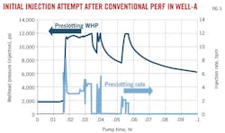
Fig. 5 presents the pressure and rate profile after conventional perforations. The dark and light blue lines in Fig. 5 present the wellhead pressure response and the attempted injection rate profile. Consequently, the interval was sand-jetted at the initial interval and a further 10 ft was added.
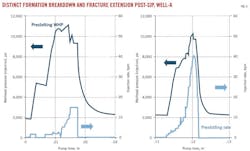
The red and pink lines in Fig. 6 present the wellhead pressure and injection rate profile during postjetting datafrac treatment. It is noticed that the breakdown of the formation has occurred and a gain of about 2,000 psi in wellhead pressure achieved.
Subsequent to the SJP treatment, the well was successfully fractured with more than 300,000 lb of 20/40 and 16/30 mesh proppant types at a rate of 40 bbl/min. The treatment plot in Fig. 7 shows the proppant concentration, wellhead and bottomhole pressures (BHPs), and injection rate along with simulated match points to compute fracture dimension.
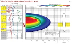
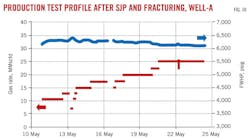
Fig. 8 presents the reservoir lithology, achieved propped fracture dimension, and conductivity. The detailed formation lithology, porosity profile, and fluid saturations along with perforation location are provided in Fig. 9. The high well performance and rate sustainability are indications of good reservoir quality, good wellbore/reservoir connectivity, and a successful proppant fracturing (Fig. 10).
Tight gas reservoirs
Tight gas is defined as reservoirs that can neither be produced at economic flow rates nor recover economic volumes of natural gas unless a specified technique is used to stimulate production.7
Depending on the reservoir rock properties, production from tight gas can require either (a) massive multiple hydraulic fracturing, and-or (b) advanced drilling, such as horizontal or multilateral wells to obtain maximum reservoir contact.
Unconventional or tight gas has proven to be a large source of energy resource in every basin that produces a large quantity of hydrocarbons from conventional reservoirs. Optimal exploitation of tight gas needs to be studied and initiated for economic production.
It is well understood that regardless how a stimulation job is executed, the well will only produce at a rate and pressure depending on the reservoir potential.
Reservoir quality, such as porosity, permeability, reservoir heterogeneity and layering, wellbore/reservoir connectivity, in situ stress, etc., are some of the most important parameters used to predict well performance. As such, petrophysical evaluation and understanding flow and geomechanical properties are essential.
In addition, the GIP and in situ stress direction determine the number of wells to be drilled, the well spacing, the well azimuth, and the hydraulic fracturing strategy to efficiently exploit a reservoir. Estimated ultimate recovery (EUR) helps performing economics so that realistic expectation can be set in terms of drilling and expected well performance prior to reservoir development.
Example wells: Well-B and Well-C
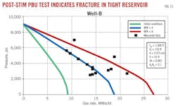
The inflow performance rate (IPR) plot from a tight gas example, Well-B, is presented in Fig. 11.6 The well, initially drilled as a vertical well, tested about 8 MMscfd at 1,900 psi after hydraulic fracture treatment. The well was subsequently sidetracked with a reservoir contact of 1,400 ft, completed with MSF completion, and successfully fractured in four stages.
Using the initial well conditions (unfractured), the well is expected to produce at about 7 MMscfd at 3,000 psi BHP. The actual measured production data after fracture treatment was matched with the option of four transverse fractures (blue curve, Fig. 11).
An additional run was made with eight fractures to show that the well rate could have further improved; however, the major assumptions in prediction runs are that the reservoir and fracture properties stay constant, reservoir homogeneity is maintained throughout the drainage area, fracture treatment is implemented as designed, and posttreatment cleanup restores 80% of the original proppant conductivity.
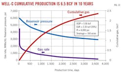
Another actual example of Well-C is illustrated in Fig. 12 from a tight gas reservoir.6 In this case, the reservoir pressure is lower than that of Well-B and the formation quality is also much poorer. The postfracture history matching showed two decent hydraulic fractures.
Long-term production forecast performed using an analytical model and illustrated in Fig. 12 predicts about 2.4 bcf of produced gas in 10 years. The EUR depends on the reservoir properties as well as wellbore configuration, well spacing, and hydraulic fracturing characteristics.
Both Well-A and Well-B are expected to yield better performance once the fracture is properly cleaned up. With the remainder of the fracture gel residue, the well performances are hampered as will be illustrated later in this article.
Next: Hydraulic fracturing and selecting the perforation interval.
The authors
CorrectionThe affiliation for an author of "Model optimizes sandstone-conglomerate fracturing in China" (OGJ, Jan. 9, 2012, p. 84) was incorrect. The correct information is as follows: Weiqiang Feng |
More Oil & Gas Journal Current Issue Articles
More Oil & Gas Journal Archives Issue Articles
View Oil and Gas Articles on PennEnergy.com
