Device capitalizes on flow stream strengths in pumping gas wells
David Simpson
MuleShoe Engineering
Flora Vista, NM
Using downhole pumps to lift interfering liquid from gas wells is not a new activity. Using these pumps at very low surface pressure is also not a new activity.
Designing wellsite facilities that capitalize on the strengths of the flow streams while minimizing the weaknesses is a very new activity.
The decision points that a facilities engineer usually had to consider were:
1. Horizontal vs. vertical production unit.
2. Two-phase vs. three-phase production unit.
3. Pipe size and pipe material.
4. Whether to tie the tubing stream into the production unit vs. going directly to a tank or the gathering system.
Eliminating the production unit was not within the engineering scope. Degassing the liquid stream at high pressures was not within the engineering scope. Producers are slowly beginning to question both of these design limitations.
Production units
Historically, production separators have generally been required for the gas stream on any gas well.
The genesis of this "rule" goes back to the early days of gas production when there was a limited market for natural gas and the only reason for producing a gas well was to recover hydrocarbon liquids.
Unfortunately, this rule has clung to the industry long after its universal validity ended. Many of the target formations for development today have near zero condensable hydrocarbon vapors and zero liquid hydrocarbons. Coalbed methane and shale gas are prime examples of truly "dry" (i.e., no recoverable liquid hydrocarbons) gas production.
A detailed analysis needs to be performed on each formation to determine what surface equipment is required for that particular reservoir. Fortunately, the majority of this analysis has been completed, albeit with alternate goals. I'm referring to "critical velocity" analysis that tries to describe the gas velocity at the onset of liquid loading in a flowing well. This work was first documented by Turner et al. in 1969.1
Turner's conclusion was that at some increasing velocity, the ability of a gas to carry a liquid improves to the point where it becomes a reliable way to remove liquids from a wellbore. This work was performed at very high flowing tubing pressure and included a mathematical model of the observed phenomena.
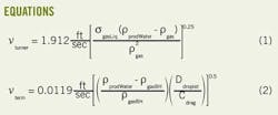
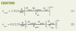
The basic form of his equation is shown in Equation 1 (the constant presented here is different from his paper because the constant in his paper was for different units than the paper called for).
Unfortunately, Turner's work was done at relatively high pressure and his model was not scalable to significantly lower pressures.
Coleman et al.2 proposed in 1991 that at lower pressures the droplet geometry devolves from Turner's spherical model to an oblate spheroid and developed a new model for bottomhole pressures around 600 psig. Coleman's model has the same form as Turner's but with a different (lower) constant.
For even lower pressures, Li et al. in 20013 flattened Coleman's oblate spheroid into a torus with a membrane filling the center. This model leads to the conclusion that at lower pressures droplets can move more efficiently and again developed the same basic model as Turner with an even lower constant than Coleman.
For most CBM flows, the Li model is the most appropriate of the three.
The most significant limitation with all of these models is that none of them includes a liquid-quantity term. Turner found in his research that below 100 bbl/MMcf critical velocity was independent of water/gas ratio (WGR). Coleman found that his equation was independent of WGR when liquid flow rate was below 220 bbl/MMcf. Li didn't indicate the maximum WGR that his model could tolerate but implied that Coleman's calculation was valid for his model as well.
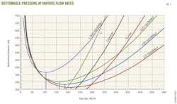
H.E. Gray published a far more complex model in 1978 that includes liquid volume explicitly and generally predicts an onset of loading that is somewhat lower than Turner, Coleman, or Li. In Fig. 1, the lines labeled with a WGR are the Gray's correlation (the vertical stubs represent the minimum stable flow rate for the WGR).
All of these models implicitly start with a fluid-drag model. This is the same starting point that a production-separator design-model starts with. All of these models acknowledge the observation that a gas operating on a liquid will have some amount of "drag" (i.e., the gas will tend to move faster than the liquid). Looking at a drag model will define a useful term called "terminal velocity" (i.e., the maximum velocity that a body will achieve while falling through a Newtonian fluid). One model is shown in Equation 2.
The drag coefficient (cdrag) is an empirical function of Reynolds Number, which is a function of velocity, so this equation must be solved iteratively. Any given size droplet will have a maximum velocity at which it will fall. In separator-sizing calculations, the goal is to reduce gas velocity to significantly below the terminal velocity of the expected droplet size. This calculation assumes a constant droplet size.
Constant droplet size is a reasonable assumption for separators because the separator wall is "infinitely far" from the bulk of the flow (i.e., nearly 100% of the total flow is more than 100 times boundary layer thickness away from the vessel wall, or in excess of 10,000 microns from the vessel wall).
For annular flow this analysis is not quite as valid. Putting tubing inside of casing creates a toroidal flow profile with a maximum velocity in a ring at the center of the annulus.
For 23⁄8 in. tubing in 7-in. casing, the distance from the no-flow boundary at the casing wall to the no-flow boundary at the tubing wall averages 2 in. Then, 20,000 microns (100 times two boundary layers) is 0.8 in., so only the 1.2 in. in the middle of the annulus can be considered "infinitely far" from the pipe wall; that is less than 80% of the flow.
Collisions with the pipe wall will be too common for the "infinitely far" assumption to be valid. When droplets hit the pipe wall or each other, they tend to coalesce into larger droplets with larger cross-sectional area and faster terminal velocity. As the droplets combine into suitably large droplets they will fall against flow. As these falling droplets hit rising droplets the rising droplets will tend to accumulate into the larger mass and fall even faster. Basically, the constant droplet size is not useful in calculating separation efficiency in an annular space.
Gray's Correlation is one of the most comprehensive evaluation methods of vertical flow. If you look at the Gray's lines in Fig. 1, you'll see (from left to right) a section that approximates a straight line, a section that approximates a parabola down to the minimum, a section away from the minimum that looks like a higher order function, and finally a section that approximates a straight line.
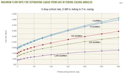
The first transition from a straight line to a parabola happens at a flow rate that is about half of the minimum (this point is where velocity effects begin to be a measureable portion of the total backpressure). If you take that point as the maximum flow rate at which the annular space can be assumed to be an adequate separator then the maximum flow rate for annular separation is shown in Fig. 2 for various WGR.
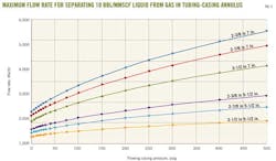
For a pumping well, it is assumed that the bulk of the liquid will be pumped, so it is generally safe to assume that the liquid in the annulus will be 0-10 bbl/MMscf. Looking at the 10 bbl/MMscf case for various tubing sizes yields Fig. 3.
Fig. 3 shows that for many pumping gas wells the tubing/casing annulus will provide perfectly competent separation for projected flow rates and target pressure. The ramification of this observation is that for many gas wells the wellsite production unit is redundant and adds to the site complexity without adding value.
The advent of "smart dump valves" like the patented Fisher easy-Drive, which provide a dump counter and an open-duration register, allows a producer to see for a particular well how often the separators dump. For low-pressure pumping gas wells this dump frequency is showing up as once or twice per month when the liquid stream bypasses the production unit. In other words, the liquid is not moving with the gas other than as the result of evaporation, and the only liquid that arrives at the production unit is water vapor that happens to condense prior to the exit of the production unit.
Degassing liquid stream
Every downhole pump caries some amount of gas. There is dissolved gas, entrained gas, and gas slugs.
The affinity of natural gas to dissolve in water is a function of pressure and temperature, but even at the highest pressures the quantity of gas that can dissolve is quite low (in the range of standard cubic feet per barrel instead of thousand standard cubic feet per barrel).
The amount of entrained gas has rarely been quantified, but recent field tests have found that numbers between 6 Mscfd and 250 Mscfd are very common. That quantity of gas in a water stream creates economic, environmental, and safety issues that have been with us always.
Gas slugging through a pump seems to be a relatively rare occurrence and is occasionally the cause of pump failure.
Entrained gas and gas slugs are the reason that most producers route pump discharge to production units.
Downhole pumps typically have excess power available. We oversize pumps both in terms of achievable differential head and maximum pumping capacity because it is very expensive to pull a pump from a well to change pump size. In general terms, adding a backpressure valve on a downhole pump discharge will improve pump performance by allowing it to operate closer to its design conditions (i.e., a small amount of gas in the pump discharge can significantly lower the actual pump discharge which shifts the operating point on the pump curve).
When we pump into a production unit, it is common for the required water side pressure to be higher than the required gas side pressure. This results in one of two scenarios: (1) hold backpressure on the entire separator to allow the water side to enter the water system; or (2) add additional equipment like a blowcase or a transfer pump to shift the water. The first scenario will often reduce gas production and revenue. The second scenario discards the downhole pump pressure capacity and then adds new energy sources to move the water.
Once gas enters the water system either due to ineffective separation or no separation, it tends to collect in high points within the system. The ramification of gas in high points is that it interferes with the liquid-flow dynamics and can significantly increase the pressure drop across the water system.
A water system that is liquid-full will require inlet pressure equal to: (1) outlet pressure plus; (2) flowing friction plus or minus; (3) elevation difference between inlet and outlet times the hydrostatic pressure gradient (0.43 psi/ft for pure water). For a liquid-full system the height of intermediate elevation changes is irrelevant to the calculation.
When gas accumulates in high points then the rebound or "siphon effect" on the downhill side of hills is negated, and the inlet pressure required due to hydrostatic gradient becomes the sum of the height of each of the uphill runs times the water gradient (the downhill runs are irrelevant). In hilly terrain this effect can add significant backpressure to the system.
We try to reverse this "gas lock" effect by placing manual vents and "air eliminators" at the high points of the water gathering system. This equipment causes as many problems as it solves. Manual vents must be accessed by operators (often a difficult trip) and the tendency is to wait for a major inlet pressure increase before bothering to access them.
Automatic air eliminators have come to us from the irrigation industry and were designed to remove air from irrigation lines. Atmospheric-pressure air does not have a commercial value, so this equipment vents the gas accumulation directly to atmosphere. The equipment does not have much residence volume so it always spits some amount of water along with the vented gas, creating a considerable mess in terms of both rusted pipeworks and accumulated solids from the produced water.
Paradigm shift
The combination of very limited water in production units on pumping wells and gas in water gathering systems is forcing a paradigm shift.
The industry has had to ask the question, "What should wellsite equipment look like if the tubing/casing annulus was truly an effective separator but we still need to remove gas from the water system?"
The first thing to consider is eliminating the production unit altogether. For two-phase systems with just gas and water this has considerable attraction both in terms of capital cost and in terms of maintenance requirements. For three-phase systems you have to rethink phase separation, and the resulting equipment looks very different from the historical HLP-type vessel where the gas and liquid are separated at high pressure (the "H" in "HLP") and the liquid is further separated at very low pressure (the "LP" in "HLP").
In the new paradigm the gas from the tubing/casing annulus bypasses the vessel entirely and the three-phase separator remains at a fairly high pressure until the water exits. Degassing either liquid stream at high pressure is a significant technical challenge.
The second consideration in the new paradigm is capturing the gas from the water stream before it can enter the water system. Notice that the consideration is "capturing," not "eliminating." One of the first wells equipped for this concept had 244 Mscfd going through the downhole pump. At the then-current market this gas was worth nearly $1,000/day. Recovering that gas for sales resulted in paying for the equipment change easily within the first month of operation.
Exhaustive product searches in 2008-09 failed to find equipment suitable for wellsite installation that satisfied the requirements of the new ideas. The primary factor that was missing was the ability to capture gas at high pressure from a water stream. There was a lot of equipment designed to remove gas from liquids, but it all resulted in the gas being near atmospheric pressure, or it required continuous-phase gas. Neither design approached satisfying the current needs.
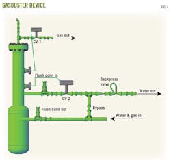
The GasBuster (patent pending) device in Fig. 4 was developed to specifically address the current needs. The vessel is small because it doesn't rely on drag effects and terminal velocity for separation, it operates at high pressure without imposing any backpressure on the reservoir, and it uses downhole pump energy to distribute the separated fluids to their respective flow streams.
In normal operations the gas vent (CV-1) is shut and the water outlet (CV-2) is open. Well fluids enter the outer vessel tangentially and the gas is separated from the liquid and transported to the top of the vessel through a standpipe.
When enough gas accumulates to transition the top float switch to not floating, CV-1 opens to let the gas go to the sink. The backpressure valve is set to ensure that the GasBuster is at higher pressure than the gas sink, so the gas exits to the sink rapidly. During the vent cycle, the downhole pump is still pumping so the liquid level rises and changes the state of the top float to "floating" and CV-1 shuts.
The vessel is now at some intermediate pressure between the gas sink and the backpressure valve setting. As wellbore fluids are pumped into the vessel the liquid level rises and compresses the residual gas at the top of the vessel. Eventually the pressure in the vessel rises enough to open the check valve and flow water to the water system.
This process happens as often as necessary, and the vent valve has been observed to cycle multiple times per minute in very gassy streams to once per hour in streams that are barely gassy.
The most cost effective gas sink is to run the vent line back to the offside casing wing valve on the wellhead. This location is preferred because if CV-1 ever fails open, putting the stream into the wellbore allows the water to simply be pumped back to surface without flooding any surface equipment. It is also effective to take the line from CV-1 to a production unit if there is one on site. Finally some producers pipe the line from CV-1 directly to the gas gathering system, but this has resulted in overfilling equipment designed for minimal water when a level switch stuck in the up position.
Water-outlet motor valve (CV-2) is installed to protect the water system from receiving large quantities of gas when the well slugs gas through the pump. When the bottom float stops floating CV-2 shuts to maintain the water seal between the gas and water. These valves rarely operate in field conditions.
To date 20 GasBusters have been installed, and we've found that downhole pumps make 6 to 250 Mscfd of entrained gas. These vessels also support the concept that traditional gas/liquid separators are not necessary on a large number of pumping gas wells.
References
1. Turner, R.J., et al., Journal of Petroleum Technology, November 1969.
2. Coleman, S.B., et al., Journal of Petroleum Technology, March 1991.
3. Li, M., et al., SPE 75455, SPE Permian Basin Oil and Gas Conference, Midland, Tex., May 15-16, 2001.
The author
David Simpson ([email protected]) is proprietor and principal engineer of MuleShoe Engineering and has 32 years' experience in oil and gas. Based in the San Juan basin in northern New Mexico, the company addresses issues in coalbed methane, low pressure operations, gas compression, gas measurement, field construction, gas well deliquification, and produced water management. Simpson was formerly a facilities engineer for Amoco and BP for 23 years. He has a BSIM from the University of Arkansas and an MSME from University of Colorado.
