JIP modification improves lateral buckling measurement, prediction
Ayman Eltaher
Aiman Al-Showaiter
M. Kabir Hossain
Paul Jukes
MCS Kenny Inc.
Houston
| Based on presentation to Deep Offshore Technology International, New Orleans, Oct. 11-13, 2011 |
A modification to the Safebuck joint industry project's V/SuD dimensionless parameter to account for the effect of pipe buoyancy due to soil weight, especially for pipes of deeper initial penetration, could reduce the scatter of predicted response when quantifying lateral buckling of subsea pipelines.
This article introduces a critical depth defined as the depth of the pipe center at which a surface-shallow buried pipe stops behaving as a surface-shallow buried pipe, and the opposite for deep-buried pipes.
The offshore pipeline industry is trying to understand and quantify the response of pipelines under lateral buckling, with the Safebuck JIP one example of these efforts.1 2 Safebuck recommends using a dimensionless parameter to predict either of two distinct behaviors of a pipe moving laterally on the seabed in situations such as lateral buckling.
The dimensionless parameter measures the ratio of pipeline weight to seabed strength, given as V/SuD, and distinguishes between responses of what are termed "light" and "heavy" pipes. The former has the above parameter below 1.5 and is characterized mainly by staying on the seabed surface, whereas the latter is defined as having the above parameter above 2.5 and is characterized by the pipe tending to dig downward below the seabed surface while moving laterally.
Fig. 1 shows the pipe displacement-soil resistance responses of the two categories.
The JIP and other efforts have performed a number of lab and field tests, used to validate this parameter and the two distinct responses.1 2 A minimal number of tests, however, addressed the response of heavy pipes.
This article will attempt to qualify the identified parameter and response characterizations, as well as identifying possible cases that deviate from these characterizations, through the use of the theory of plasticity and its normality conditions as well as state-of-the-art finite element (FE) simulation. The latter consists mainly of the coupled Eulerian Lagrangian (CEL) FE method, provided by Abaqus.3 This method has shown great potential and good fidelity in simulating pipe-soil interaction, as well as many other situations involving extreme deformations.4 5
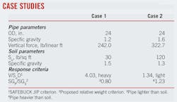
The accompanying table details the parameters of pipe-seabed interaction during lateral movement for the pipe and seabed configurations. The Safebuck criterion categorizes Cases 1 and 2 as "heavy" and "light," respectively, although the actual weights could arguably be the opposite if only the weight of the pipe relative to weight of the soils of the same volume (SGp/SGs) were considered.
These two cases used conditions in which the pipes either lie on the seabed surface or are buried so deeply that the pipe response is not affected by any surface events. Unless stated otherwise, all values given in the discussion or figures are considered for 1 ft of the pipe length.
Deeply buried pipe
A pipe buried deeply, so that surface effects on its behavior are negligible, responds to loading in a simple infinitely symmetric manner. In particular, the infinite-circular symmetry leads, by inspection, to symmetry of the failure envelop (i.e., the failure envelope is circular) and the pipeline trajectory has the same direction as the load. Equations 1 and 2 show the angle of pipe movement trajectory.
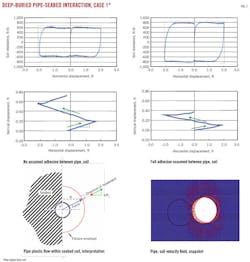
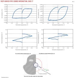
CEL FE simulations validated these relations for the cases in the table, with the output shown in Fig. 2 for two bounding conditions, namely where the soil was either allowed or not allowed to separate from the pipe at the tensile side. Fig. 2 shows the pipe displacement-soil resistance response as well as the pipe movement within the seabed soil, interpreting the mechanics of pipe movement based on the plasticity theory and its normality condition.6
The CEL FE predicts a response that is characterized by an ascending-floating trajectory when the pipe moves laterally (Fig. 2), allowing interpretation which shows that for the case of deep buried pipe, movement is controlled by the pipe weight relative to the soil weight (i.e., SGp/SGS) as opposed to Safebuck's V/SuD parameter (the latter having been derived mainly for surface pipes). The relative pipe-soil weight indicates a pipe lighter than soil, whereas the Safebuck parameter indicates a heavy pipe.
The value of the trajectory slope (of 0.10) calculated in the box coincides well with that shown in Fig. 2. The angle of ascent of the pipe movement is smaller for the case with full soil-pipe adhesion, explained by the larger soil resistance in this case.
Fig. 3 shows a similar response in the case of a pipe heavier than soil. The major difference in pipe response in this case is the pipe digging farther down (descending) when it is moves laterally; again, governed by Equation 1.
Surface pipe
A surface pipe responds to loading in a more complicated manner than that of deeply buried pipe. The envelope of the soil resistance to pipe movement is not infinitely symmetric around the pipe. The trajectory of a load-controlled pipe, right after soil yielding, is likely to have a different direction than that of the load, as the direction of pipe movement will be perpendicular to the soil resistance-yield surface.
Surface effects such as the forming of a berm ahead of a light pipe as it scrapes the seabed surface and flow of the soil on top of a heavy pipe while it dives down (the relationship Pu = Nc ∙ Su no longer being linear or straightforward) further complicate soil resistance and make it highly nonlinear.
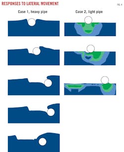
Fig. 4 shows CEL FE simulations for Cases 1 and 2, given in the table, consistent with descriptions in Bruton et al.1 2 for heavy and light pipes. Figs. 5 and 6 provide interpretations of the two distinct responses, respectively, with correlations to the plasticity theory and normality conditions. The latter is illustrated by way of plastic failure envelopes and pipe movement perpendicular to the envelopes.
The figures also show that, on the surface, the soil failure envelope is symmetrical only around the vertical axis and that soil resistance to pipe upward movement is smaller than to downward movement, mainly due to the limited adhesion between the soil characteristic of smoother or coated pipes and total or partially drained conditions. Ultimate capacity of reverse-end bearing (under tension) is also usually less than compressive-end bearing.
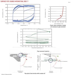
The soil failure envelopes were derived through displacement-controlled series of CEL FE simulations, with the pipe displaced in different directions (e.g., 0˚, 22.5˚, 45˚, etc., to horizontal) and magnitude and direction of soil reaction reported at time of failure. Load-controlled simulations (which usually provide a smoother response) were at times performed to double-check the displacement-controlled results. Failure occurs where the total displacement is twice the elastic displacement. Fig. 7 shows derivation of a point on the failure envelope.
The top of the series of images that depict the heavy-pipe response (Case 1) in Fig. 4 shows the initial penetration to be about 75% of the pipe diameter; i.e., the pipe is almost buried initially. The top chart of Fig. 5 shows the displacement-resistance response, clearly displaying an increase in soil resistance during plastic flow, which corresponds to pipe dive down. The X-Y displacement-trajectory chart indicates an extra 1.75 ft of penetration by the end of the first cycle of lateral displacement, by which time the pipe has already been completely buried and the force response virtually stabilized, as shown in the displacement-force response chart.
The normality condition of the plastic flow, shown in the bottom left schematic of Fig. 5, controls the response of the pipe after breaking out and makes it dive downward. The dive rate decreases with the increase in depth, as conditions change and get closer to those of deeply buried pipe. The latter tend to drive the lighter-than-soil pipe upward.
The pipe trajectory eventually reaches a stable steady-state condition, where the shallow and deep pipe tendencies balance and a pure horizontal motion dominates, as shown in the pipe movement-trajectory chart. This balance is also shown in the residual condition (lower-right, Fig. 5) schematic, where the soil plastic failure envelope has a characteristically vertical tangent when the pipe is pushed horizontally.
Based on the case illustrated in Fig. 5, critical depth can be defined as the depth of the pipe center at which the pipe stops behaving as a surface-shallow buried pipe. This depth is defined only for pipes that are categorized as heavy based on Safebuck's V/SuD parameter but lighter than soil. A pipe of the same characterization but buried deeper than critical depth is likely to climb up and stabilize vertically at the critical depth. Further study is needed to verify these conclusions and to identify how the critical depth depends on the pipe and soil parameters.
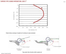
Fig. 6 illustrates fundamentals of the pipe-soil interaction for light pipes, which follow bases of plastic failure and normality conditions similar to the heavy pipe but with different conclusions. The soil plastic failure envelope, as derived from FEA, is shown at the top of the figure, and the lower left schematic illustrates the expected direction of pipe movement perpendicular to the envelope at the moment of breakout. Based on the schematic, the pipe would initially tend to climb the initial penetration, and at residual condition the envelope would have changed to force a horizontal plastic displacement.
FEA predictions of the response of surface pipes to lateral forcing are in line with characterizations of Safebuck. To parallel the physics of the problem further, however, this article proposes modifying the definition of the vertical force, V, to be the difference between the pipe weight and the weight of displaced soil.
This modification will reduce the value of V for the whole set of data used to derive the heavy-light border for Safebuck's dimensionless parameter. It will also, however, tend to reduce the value of heavy pipes more than it will light pipes, in turn reducing or potentially eliminating the current gap (grey area) between heavy and light pipes (the values of V/SuD between 1.5 and 2.5). The value modification will also reduce the scatter of the predicted response to pipe lateral displacement.
References
1. Bruton, D., White, D., Langford, T., and Hill, A., "Techniques for the assessment of pipe-soil interaction forces for future deepwater developments," OTC 20096, Offshore Technology Conference, Houston, May 4-7, 2009.
2. Bruton, D., White, D., Carr, M., and Cheuk, C., "Pipe-Soil Interaction during Lateral Buckling and Pipeline Walking—The SAFEBUCK JIP," OTC 19589, Offshore Technology Conference, Houston, May 5-8, 2008.
3. SIMULIA, "Abaqus 6.10—User Manual," 2011.
4. Eltaher, A., Al-Showaiter, A., and Jukes, P., "Analytical Tools for Offshore Arctic Challenges—A State of the Art," Deep Offshore Technology, Houston, Feb. 2-4, 2010.
5. Eltaher, A., Hossain, K., Jafri., S., Banneyake, R., and Jukes, P., "Offshore Geotechnical Applications of Eulerian Finite Element—A State of the Art," International Offshore Pipeline Forum, IOPF2010-3002, Houston, Oct. 18-20, 2010.
6. Chen, W.F., "Limit Analysis and Soil Plasticity," Elsevier Scientific Publishing Co., Amsterdam, 1975.
The authors
More Oil & Gas Journal Current Issue Articles
More Oil & Gas Journal Archives Issue Articles
View Oil and Gas Articles on PennEnergy.com
