The export system
The team charged with designing Perdido’s oil export system reviewed all their options. There were few. The Perdido spar is moored more than 60 miles south of it’s nearest deepwater neighbor. It is 140 miles from the closest shallow-water platform, and the distance in between covers some of the most challenging terrain in the Gulf of Mexico.
The gas export pipeline was routed to the Seahawk Pipeline (107 miles from Perdido), which was installed with subsea facilities for a future connection. The closest oil pipeline, however, had no such connection. Perdido is 77 miles from the Hoover Offshore Oil Pipeline System, commonly called HOOPS. Transportation through HOOPS would require the first installation of a diverless, subsea connection.
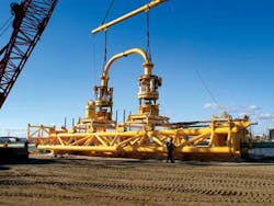
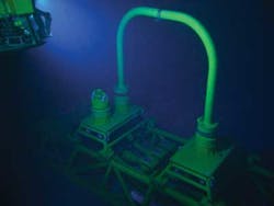
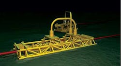
In a clear break with conventional tie-in projects, a new technique was developed that utilized a truss structure as both a foundation and reference system for the installation of the connection hardware. The foundation enabled the Perdido export connection to be fabricated onshore and reassembled on the pipeline. It was the first time that a tie-in used a common foundation and prefabricated jumper spool.
The oil export connection
In shallow water, it is not difficult to tap into a pipeline full of oil, it’s called a hot tap, but no one had tried it before in 4,500 feet of water. While the actual connection took just 17 days to complete, preparing for the job took two and a half years.
“We learned a lot in that time, and the design evolved,” Dupré says. “We applied some new tools, did plenty of 3D modeling, and practiced using ROV simulators to walk through the connection. Because we would be working with a pipeline that has been in service and the majority of the pipeline would still be full of oil, there was no room for error.”
In a more typical subsea repair, the pipeline would be shut down, displaced and then cut. Fittings would be placed over each end, then divers or an ROV would measure the length and orientation of the jumper needed to connect them. The jumper itself would be fabricated onshore and returned to the field for installation. The process would take up to 90 days. Even if divers could work at the depth of the HOOPS connection, the pipeline could not be shut down for that long.
The engineering solution was to create a single structure, a common base that could straddle the pipeline and serve as a positioning reference for tools and the placement of new hardware.
“We started with a simple, conventional design using two sleds and a jumper in between,” Dupré says. “There were certain criteria to follow. We couldn’t release any oil, of course, we could use only proven components, and we had to minimize the time the pipeline was out of service.”
Another criteria was that the connection could be reconfigured in the future. Designers were looking ahead; Hoover-Diana had already been producing for 10 years, so at some point, ExxonMobil might want to disconnect from HOOPS, and new operators in the area might need to tie in.
The key component of the new connection system was a truss-style structure. The structure is 100 feet long, 10 feet tall and 40 feet wide, but made of large diameter members so it could be made buoyant in water. Once it was landed over the pipe, all of the ROV tools and connection components referenced off the base, so every measurement was precise.
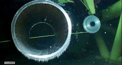
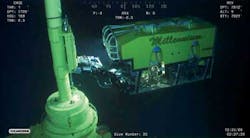
“Subsea construction was limited to ROVs and ROV- based tooling,” Dupré explains. “Each tool that was deployed was referenced to the foundation. ROV tooling was used to remove the pipe seam, remove the coating, make the cuts and prepare the cut ends. Positioning of the new connection hardware over the cut pipe ends was also referenced to the foundation, allowing precise alignment of components. When it was time to install the final jumper, we didn’t have to take measurements and go back to the beach for fabrication. We knew exactly the length and orientation, so we were able to prefabricate the jumper. This allowed the entire operation, which was completed in March 2009, to be completed while impacting production by only 17 days.”
A delicate touch
Since the HOOPS tie-in required placing a large structure over an existing pipeline, designers of the system spent much of their time thinking about how to do it safely. Instead of trying to lower the heavy truss onto the pipe, the truss itself was designed to float. If the truss broke free, the structure was going up, not down.
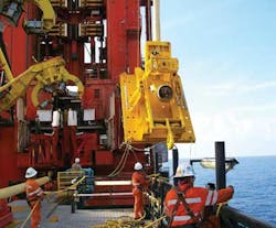
As the truss neared its target, ROVs secured clamps to pull it down over the pipeline. Once the truss was positioned properly, the hollow pipes in its frame were progressively flooded until the 100,000-pound structure was embedded fully in the seabed. Using this stable base, the pipeline was then raised a short distance to allow 360-degree access for the tools.
“So the frame went in first,” Dupré says. “Then we had to clean and cut the pipe. We needed to take out a total of 28 feet from the middle.”
To thoroughly clean the pipe, the team ran a series of four high-tech pigs from the Hoover platform. Radioactive markers inside the pigs allowed the pigs to be tracked and positioned in the line.
Between each pig was a slug of water. Pigs one and two were allowed to pass the point where the pipeline would be cut, while pigs three and four were stopped before they reached the cut point. Between pigs two and three, the pipeline would contain only water, but no one wanted to take a chance on spilling any oil.
“In addition to the positioning of slugs of water and operational procedures applied at the upstream and downstream risers, we had a contingency repair clamp positioned on the pipeline next to the cut point to re-seal the pipe in case there was still some oil in the line,” Dupré says. “We also had a pollution dome over the top of the frame, so if we had any oil, we could capture it and pump it into a subsea reservoir for recovery. We had all of these contingencies in place, but when we made the cut, nothing came out. The pipeline was completely clean.”
The flowline system
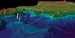
As pipeline engineers like to complain, drillers always manage to find oil in the worst possible place. Perdido is a prime example. Besides the extreme water depth, there’s a wide and 1,000-foot deep canyon just north of the spar, between the spar and the export systems. To the south and east, the export and the subsea lines to satellite wells also had to avoid steep slopes and chemosynthetic communities of environmentally-sensitive creatures.
Surveys covered more than 1,000 miles of the sea floor to find suitable routes. As a result, all of Perdido’s flowlines now run through very narrow corridors. Even the export lines exit the spar to the south, then make a large u-turn before heading north.
“On the flowline side, we’re having to contend with extremely deep water,” Dupré says. “Some of our flowlines are more than 9,700 feet deep. That means some of them are shorter than the water depth, which makes it much harder to install the lines from a vessel on the surface. At some point, the entire flowline is hanging below the vessel.”
Sally Simmers, flowline engineer, managed the flowline and riser installation contracts.
The flowline system is comprised of production flowlines, water injection flowlines, and utility lines to circulate oil for flow assurance. Each had it own unique design criteria. Insulated with GSPU (a wet insulation for subsea pipelines), the production lines extended to the deepest portions of the field, routed around deep slopes and seafloor features. The water injection flowlines utilized both an internal and external fusion-bonded epoxy (FBE) coating. An alternative to a clad pipe or polymer liners, the internal FBE provides corrosion protection to prevent potential plugging of the water injectors. Even the small diameter circulation line provided unique challenges in routing across a difficult seafloor, where piles had to be installed to accommodate the multiple spans. In addition, because of installation vessel availability, this majority of the construction was completed during an active 2008 hurricane season.
“The Perdido Pipeline and Flowline Team kept its focus on safety, overcoming many technical challenges to deliver a robust solution for the Perdido Project,” Dupré says.

