GAS HYDRATES - 1: Lab work clarifies gas hydrate formation, dissociation
Experiments show that ensuring oil and gas production under certain pressures and temperatures requires a thorough understanding of the effects of inhibitors on gas hydrate formation and dissociation.
Without this understanding, production costs can become excessive either because of flow blockage or the use of unnecessary amounts of inhibitors.
This first article in a two-part series covers some aspects of hydrates; the concluding part will illustrate the morphology and kinetics of hydrates formed in the laboratory using various mixtures.
Although theory can help one to understand some aspects of gas hydrates, we need to emphasize that the formation and dissociation of gas hydrates is a complex process that is affected by many variables. Detailed kinetic studies in the laboratory are required to fully understand how hydrates form and dissociate.
This series of articles presents new results from experiments in which gas hydrate kinetics and morphology were investigated for a variety of gases and liquids, in both static and dynamic conditions, and in the presence of methanol and some kinetic inhibitors.
Gas hydrates
Scientists have known about gas hydrates for more than 200 years.1 Serious research on gas hydrates by the oil and gas industry dates back for 60 years.2 Gas hydrates also exist naturally on both land and in the oceans (see sidebar).
Gas hydrates are clathrate inclusion compounds in which gas or volatile-liquid molecules no larger than 0.83 nanometer are hosted in a crystalline lattice formed by hydrogen-bonded water molecules.
Several mathematical models can predict the conditions at which hydrates form or decompose. These models are based on the chemical potential of water and the energy of intermolecular bonds.
At certain pressures and temperatures, gas hydrates will form in wells, pipelines, and surface facilities.
Methanol is commonly injected in the fluid stream in an attempt to prevent the formation of gas hydrates. The methanol for preventing hydrate plugs costs the industry more than $1 million/day. This expense does not include the cost of methanol transportation, storage, and injection.
Even after 60 years of research, there is still much to be learned about gas hydrates. For example, very little is known about the kinetics of gas hydrate formation and dissolution, especially when natural gases and brine fluids are used to create the gas hydrates.
Many important aspects of gas hydrates require more research. Several of these aspects are as follows:
- Kinetics involved during the formation and decomposition of gas hydrates.
- Morphology of hydrate crystals that form inside production, transportation, and processing equipment.
- Development of effective methods for preventing and removing large hydrate plugs in wells and pipelines.
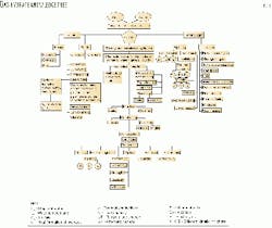
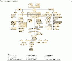
Fig. 1 illustrates the "knowledge tree" associated with gas hydrates. Part of this tree includes a better understanding of the kinetics and morphology involved with the formation and dissolution of gas hydrate crystals.
The kinetics during the formation and decomposition processes of gas hydrates are very important, yet they are one of the least understood characteristics of gas hydrates. A better understanding of kinetics is important when one wants to prevent or remove a large hydrate plug in a well or pipeline.
In addition, the kinetics of hydrate formation will control the processes involved with developing methods to transport and store gas in a hydrate state.
Research affirms that gas composition, water composition, pressure, and temperature are not the only factors one needs for determining the conditions under which gas hydrates will form. Other factors must be taken into account.
These include the amount of gas dissolved in the water, the time that hydrate formers are in contact, the structural state of the hydrate formers, the surface tension (the energy of intermolecular bonds) at the gas-liquid boundary, the rate of system cooling, and the presence of sorbents and catalysts in the system.
Hydrate formation conditions
Laboratory experiments are the only way to understand how gas hydrates form and dissolve under various conditions. In practice, however, most companies only use simple software programs to predict the behavior of gas hydrates. Such programs are based on theory, and perhaps, a few experimental results for gas hydrate dissociation equilibrium conditions.
In these programs, the main variables are pressure, temperature, gas composition, and water composition. None of the computer programs contains both the theoretical and the empirical data that encompass the entire range of pressures, temperatures, and compositions of vapor and liquid phases that one can encounter in nature.
The Ng and Sloan programs seem to be the most comprehensive. These two programs allow one to enter data for gases of various compositions, various temperatures, and pressures of up to 40 MPa, with consideration for the presence of some hydrate inhibitors in the water.
These programs can be used to predict the final hydrate dissociation, equilibrium pressure-temperature, conditions including the effects of certain thermodynamic inhibitors.
These programs, however, cannot predict when gas hydrates begin to form, the pressure and temperature conditions when gas hydrates begin the dissociation process, or the rate of hydrates formation or dissociation.
A number of analytical methods are available for estimating the equilibrium parameters when gas hydrate will begin to form. The most generalized solution, based on research concerning the molecular structure of hydrate crystals, was proposed by Barrer-Ruzichka, who made the following assumptions:
- Enclathrated hydrate-formed molecules do not form stable chemical bonds with the surrounding water molecules.
- Interaction is taking place through the dispersion forces that can be approximately described by Lennard-Jones potential or its various modifications.
- Energy of the dispersion interaction is much weaker than that of a hydrogen bond. This allows one to neglect the effect of enclathrated guest molecules on the state of water molecules in the hydrate lattice.
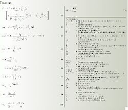
Free energy of the hydrate phase F and equilibrium conditions are expressed as Equations 1-3 (see Equation box).
In an examination of the equilibrium of a gas-water-hydrate system, the chemical potential of an i-th component in the gas phase mj' is expressed by an equation such as Equation 4.
Gas hydrate formation consists of two steps:
- Formation of a crystal nucleus of critical size.
- Growth by sorption on nucleus surface, outside surface (massive crystals), and basic crystal (whiskery crystals).
The critical size of the nucleus, rc, decreases inversely to the latent heat of crystallization, Q, and to the supercooling (Tp - To). The value ofrcdecreases directly to the nucleus' specific surface energy, s (Equation 5).
In Equation 5, Te is the equilibrium temperature of crystallization, and To is the temperature of the crystallization process.
After one or more nuclei of critical size form, gas hydrates on the free gas-water surface will grow at a constant rate for constant conditions. Eventually, the gas hydrates will completely close the free surface under static conditions.
Once the free surface is closed, the gas hydrate growth will be controlled by diffusion through the interface. The radial growth rate of the hydrate film on the free gas-water contact depends on pressure, temperature, subcooling, composition of gas and water, heat formation, and heat transfer.
Equation 7 expresses analytically the radial growth rate, vr of methane hydrate. Table 1 provides the pressure-dependant coefficients, c and d.
Equation 8 can determine the massive rate of diffusion of water, Mw, through the even hydrate film, with thickness, h, and surface, F. The Dw is the coefficient of diffusion of water through the hydrate film.
We have experimentally determined that Dw for hydrates generated using methane gas can range from 10-6 to 10-8 sq cm/sec. For a natural gas with relative density of 0.6, the Dw is 1x10⁻⁶ sq cm/sec.
In Equation 8, Df is the difference in volatility of the water vapors above the liquid and above the hydrate. The pw is the water density in the hydrate state (pw = 0.792/0.757).The amount of gas converted into hydrate (DQ) can be found when the initial volume of free gas (V), initial pressure (p0) and pressure drop (Dp) are known (Equation 9).Equation 10 can determine the volume of formed hydrates (Vh). In Equation 10, n is the molar ratio of water and gas in hydrate at formation conditions, and ph is the density of formed hydrate.
Usually, the heat of hydrate formation and the rate of heat removal determine the rate of hydrate accumulation during its formation at a free gas-liquid interface.
In the absence of a free gas-liquid interface, hydrate forms by diffusion of hydrate forming molecules (mainly water) to a growing hydrate surface. Heat transfer is more intensive than mass transfer during this process.
Diffusive permeability of the forming hydrate controls the accumulation of massive hydrate according to Equation 11.
Using Equation 11, one can evaluate the effects of diffusion and thermal conductivity on the rate of hydrate formation.
Laboratory results
Experiments investigated the kinetics and morphology of gas hydrates at pressures up to 5,000 bar and temperatures as low as -10° C., using pure gas, natural gas, distilled water, and salt water containing different inhibitors under static and dynamic conditions.
The results suggested that the kinetics of the hydrate formation and decomposition processes require more detailed experimental and theoretical studies. The experimental data, however, did provide a clear understanding of how some inhibitors affect gas hydrate properties under either static or dynamic conditions.
Existing computer models, used to determine the effects of inhibitors, should only be used for estimating the conditions of hydrate decomposition, and not the onset of hydrate formation. There is no computer model that we know of that can predict both hydrate formation and dissociation in the presence of kinetics inhibitors.
Gas hydrates will form at a lower supercooling and a higher rate of accumulation in the presence of an inhibitor. The strength and stability of a hydrate formed with an inhibitor, however, were lower than those of a hydrate formed from pure water.
Hydrate formed much faster under dynamic conditions in the absence of inhibitors because of a constant renewal of a gas-liquid interface. Presence of a hydrate film at the gas-water contact transformed the hydrate formation process into a bulk-diffusion type, accompanied by two to three orders of magnitude decrease in the rate of formation.
When kinetic inhibitors are used, more hydrate was formed under static conditions than under dynamic conditions because the film under static conditions was very permeable and allowed for high water molecule diffusion rates into the gas phase.
The strength of a hydrate of a natural gas decreased with heavier gas composition. The hydrate formed using natural gas was less strong than hydrate formed using methane.
Hydrates of different composition and stability formed at different degrees of supercooling.
Hydrates with pure components decomposed at a temperature greater than the equilibrium value. But natural gas hydrates started to decompose long before the temperature reached equilibrium for the test pressure, and finished decomposing at a temperature slightly over equilibrium. The strength of the natural gas hydrate decreased significantly during decomposition.
The presence of kinetic inhibitors increased the temperature at which natural gas hydrates completely decomposed. to our knowledge, there are no kinetic inhibitors that preclude the formation of gas hydrates.
The most dangerous time for wells and pipelines is an extended shut-in period. During a shut-in, hydrates will form quickly on the condensed water surface and then actively adsorbs water molecules.
The time for a formed hydrate to decompose with a kinetic inhibitor was much longer than for a hydrate formed without an inhibitor or with a thermodynamic inhibitor.
Hydrate decomposition temperature increased when kinetic inhibitors were included. Kinetic inhibitors adsorbed on hydrate crystals and stabilized hydrates, strengthened them and decreased water vapor pressure above the hydrate. Complete hydrate decomposition in the presence of inhibitors took days of superheating.
Metastability in the presence of inhibitors occurs during hydrate formation and hydrate dissociation.
References
- Priestley, J., Verssuche und Beobachtungen Uber Verhiedene Gattungen der Luft, Wien-Leipzig, 1778-80.
- Hammerschmidt, E.G., "Formation of gas hydrates in natural gas transmission lines," Int. Engineering Chemistry, Vol. 26, 1934, pp. 851-55.
The authors
Yuri F. Makogon is a visiting professor and research associate at Texas A&M University. He has more than 40 years' experience in education and research in the gas and oil industry, much of it dealing with development of effective methods for both prevention and removal of hydrate plugs in wells and pipelines.
Makogon is a member of the Russian Academy of Natural Science and was the first chairman of the SPE Moscow Section.
Stephen A. Holditch is an adjunct professor at Texas A&M University. He formed S.A. Holditch & Associates Inc. in 1977, which became a part of Schlumberger Technology Corp., and now it has been combined with other groups in Schlumberger to form Holditch Reservoir Technologies. Holditch consults for Holditch Reservoir Technologies. He has a BS, an MS, and a PhD in petroleum engineering from Texas A&M University.
Holditch was elected to the National Academy of Engineering (NAE) in 1995 and Russian Academy of Natural Sciences in 1997. He will be the SPE President in 2002.
Gas hydrates in nature
Gas hydrates have been known to form and exist in nature since 1966.1 2 These hydrates occur mainly in the subpolar regions of continents and in deepwater regions. The first naturally occurring gas hydrate field was discovered in 1967.3
Estimated gas contained in these naturally occurring gas hydrates may exceed 16 trillion tons of oil equivalent.4 5
One estimate is that 98% of these resources are offshore, while 2% are in permafrost zones on land. The 2% found on land may contain more than 300 billion cu m of gas in place, which is equal to twice the proven world natural gas reserves.
But more work needs to be done on understanding the potential of this resource and the morphology of hydrate crystals that form in porous media. Better estimates have to be made on the gas-in-place in various basins around the world.
Also, techniques have to be developed for producing gas from the hydrate-containing formations.
These hydrates may have an effect on the earth's thermal regime and generation of greenhouse gases, and they may also hold clues about the formation and dynamics of cosmic bodies.
References
- Makogon, Y.F., Peculiarities of Gas-Field development in Permafrost Zone, Nedra, Moscow, 1966.
- Makogon, Y.F., Hydrates of Natural Gas, Nedra, Moscow; 1981, and PennWell, Tulsa, 1974.
- Makogon, Y.F., Trebin, F.A., Trofimuk A.A., Tsarev, V.P., and Cherskiy, N.V. "Finding of a Pool of Gas in Hydrate state," DAN SSSR, Vol. 196, No 1. 1971, pp. 197-206.
- Makogon, Y.F., Hydrates of Hydrocarbons, PennWell, Tulsa, 1997.
- Sloan, E.D., Clathrate Hydrates of Natural Gas., 2nd edition., Marcel Dekker Inc. New York, 1998.


