Optimizing FCC regenerator can minimize catalyst losses
Proper regenerator bed level and cyclone operation are important to ensure minimum catalyst losses from FCC units. Monitoring the regenerator level in relationship to the cyclone dipleg valves and transport disengaging height (TDH) is key to curtailing catalyst losses. Absolute catalyst level inside the dipleg should be periodically evaluated to ensure losses are minimized, particularly in units that operate at high regenerator superficial velocities.
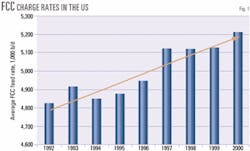
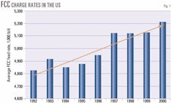
FCC unit charge rates have risen steadily in the US since 1992. US Energy Information Administration data (Fig. 1), illustrate that average FCC charge rates have climbed to 5.2 million b/d in 2000 from 4.8 million b/d in 1992.1 Over the same time period, the number of FCC units operating in the US has fallen by approximately 10%. As a result, today's average FCC unit is processing 20% more feedstock than it was 10 years ago.
Obviously, FCC operations in the US are highly constrained with new challenges constantly presenting themselves. One challenge is operating below stringent flue gas particulate-emission limits.
FCC flue gas particulate-emission requirements vary from site to site. Depending on the location, these limits are defined by the regenerator coke combustion rate (lbm of particulates per 1,000 lbm of coke burn) or by opacity measurements. The most stringent particulate-emission standards are achieved with downstream abatement equipment like a wet gas scrubber or an electrostatic precipitator.
Nevertheless, to ensure that a particular FCC unit is always in compliance, the refiner must minimize catalyst losses from the regenerator. With increased utilization, however, continuous operation below these emission limits is often difficult and, should the operation deteriorate, emission violations are possible.
Factors impacting catalyst losses from the FCC regenerator are:
- FCC unit design.
- Equipment mechanical integrity.
- Catalyst properties.
- Regenerator bed level and cyclone operation.
Regenerator catalyst level, TDH
Most refiners refer to the regenerator bed level in terms of inches of water or percent of scale. Often the bed level range, within which the regenerator operates, is based solely on experience with little understanding of the ab sol ute physical level.
Rather, the regenerator bed level should be reported in terms of an absolute level relative to a convenient reference point such as the regenerator bottom tangent line, catalyst witHdrawal well nozzle, or cyclone dipleg valve to give the operator a better understanding of the operation.
Regenerator bed level can be easily computed and displayed on the operator's control screen. A single-gauge pressure survey, preferably a digital gauge illustrating pressure in terms of inches of water, should be used periodically to verify bed level and density instrumentation.
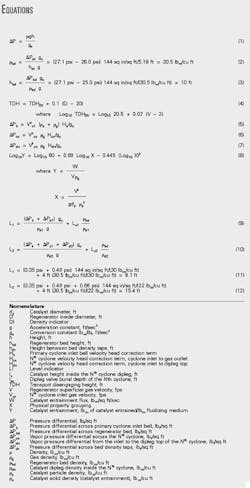
The simple hydraulic relationship in Equation 1 can be used for all bed level and density calculations in the FCC unit (see accompanying equations box).
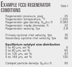
For example purposes, we use a 50,000 b/d FCC unit operating at the conditions listed in Table 1.
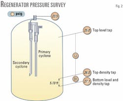
Fig. 2 lists data collected during a pressure survey along the regenerator. Measurements were taken at the bottom level instrument tap (also the bottom density tap), top density tap, top level tap, and a pressure tap in the flue gas line just downstream of the cyclones. From these data and unit operating data, the regenerator bed level, TDH, and cyclone dipleg levels can all be estimated.
Before the bed level can be calculated, the bed density must be estimated from the differential pressure measured beneath the catalyst bed. In our example, a 30.5 lbm/cu ft bed density is calculated in Equation 2 by rearranging Equation 1.
Density taps are often separated by a convenient distance so that the bed density is the same number as the differential pressure in inches of water. The same holds true in this example.
With the actual bed density, the regenerator bed level relative to the bottom level instrument tap is estimated to be 10 ft (Equation 3).
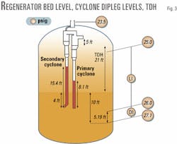
The bed level (Fig. 3) is sufficient to bury the cyclone dipleg valves by 4 ft. Subtracting the dipleg valve elevation from the bed elevation determines the burial height. Dipleg valve burial requirements, however, vary by valve type.
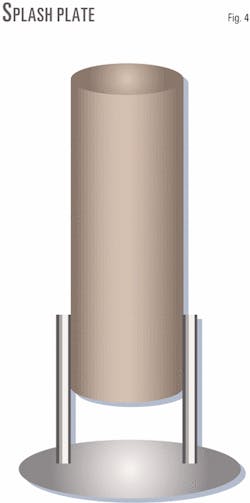
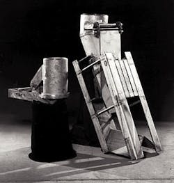
A splash plate (Fig. 4) should always be buried by the regenerator catalyst bed during normal operations. Counterweighted check valves (Fig. 5) should operate unburied.2 Flapper valves, also shown in Fig. 5, can operate either buried or unburied. Regenerator secondary cyclone flapper valves, however, should be buried to minimize losses by preventing re-entrainment of catalyst fines.3 - Counterweighted check valve (left), partially shrouded flapper valve (Fig. 5). Photo courtesy of Marsulex Environmental Technologies LLC.
Specific dipleg burial requirements should be confirmed with the FCC licensor or cyclone vendor. If the operation or design requires that the cyclone valve be buried, it should always terminate in a well-fluidized zone to ensure proper valve and cyclone operation.
TDH is the distance above the fluidized bed where the solid density (entrainment) becomes constant. The FCC regenerator bed level must be such that the TDH does not extend into the primary cyclone inlet horn. This will minimize the amount of catalyst entrained into the regenerator cyclones and catalyst losses from the FCCU regenerator.
Equation 4 estimates TDH.4
TDH is estimated to be 21 ft with data from Table 1. Fig. 3 shows that the TDH terminates 5 ft below the inlet horn of the primary cyclones. The height between the primary cyclone inlet horn and the point where the TDH terminates should be maximized within regenerator constraints.
Cyclone operation
Combustion air rates and regenerator bed level significantly impact cyclone operations. A head of catalyst in the dipleg balances the pressure drop across the cyclones. Increasing combustion air rates will increase the cyclone pressure drop, which in turn increases the necessary catalyst level inside the dipleg.
Cyclone diplegs must be long enough for the catalyst inside to build the necessary static pressure head to overcome the cyclone gas pressure drop. In some cases, high combustion air rates (significantly higher than design rates) can cause the catalyst level inside the dipleg to rise into the cyclone body, causing dipleg "flooding," significantly increasing catalyst losses.
Regenerator bed level can also influence the catalyst level inside the dipleg. An excessive regenerator bed level can cause high losses by increasing the catalyst dipleg level as high combustion air rates do.
Estimating the catalyst level inside the cyclone dipleg requires a pressure balance be made around the cyclone. Constructing this pressure balance requires an estimation of the pressure inside the cyclone hopper just above the cyclone dipleg.
The total pressure drop across the cyclone system is the sum of the acceleration pressure drop and the gas pressure drop across the primary and secondary cyclones (and, in some cases, the tertiary cyclone). In our example, DPb + DPc1 + DPc2 is equal to 1.5 psi.Equation 5 will estimate acceleration pressure drop into the primary cyclone. The relationship in Equation 6 can estimate the vapor pressure drop of the cyclones. Finally, vapor pressure drop from the cyclone inlet to the top of the dipleg is in Equation 7.
These equations are similar to those presented by Tenney and Gardner2 except, in this case, the H term is dimensionless.
Of course, the challenge with using these simple equations is determining values for the velocity head correction terms Hb, Hcn, and Hdn. Since each FCC operation and cyclone system is unique, the velocity head correction terms are unique.
In an effort to estimate Hcn, one may assume that the pressure profile across the primary and secondary cyclones is proportional to the respective velocity-squared term. This is equivalent to assuming that Hc1=Hc2. It can also be assumed that Hb << than Hcn due to the relatively large value for solid density in the DPb term compared to gas density in DPcn. For the purpose of this example, we assume that Hb is 0.5 and Hc1=Hc2. Estimating DPb requires the calculation of the solids density. Primary cyclone gas velocity and gas density, which are also required to compute DPb, are listed in Table 1. The solids density, ps, represents catalyst entrainment to the cyclone and can be approximated by Equation 8.4This equation is valid for all elevations above the TDH and must be used at discrete particle size ranges. Wilson offers a thorough explanation of the technique.5
The entrainment, W, is estimated to be 1.73 lbm/sec/sq ft in our 50,000 b/d FCC example. The solids loading, ps, is calculated from W by dividing by the regenerator velocity. In our example, ps is 0.61 lb/cu ft.
With a value for ps, DPb can be calculated and is equal to 0.35 psi. Since the total pressure drop of the cyclones is 1.5 psi, this leaves 1.15 psi to be distributed across the two cyclones.With DPc1 +DPc2 = 1.15 and Hc1=Hc2, the velocity head correction terms and pressure drop can be estimated. In our example, DPc1 and DPc2 are estimated to be 0.49 psi and 0.66 psi, respectively, and the values for Hc1 and Hc2 are 7.5.Assuming the H terms remain constant for a given system, the total cyclone pressure drop can be estimated for other operating conditions.
Equations 9 and 10 can estimate the level in the primary and secondary diplegs. For our example, we will assume a primary dipleg catalyst density of 30 lbm/cu ft and a 22 lbm/cu ft catalyst density inside the secondary dipleg. Tenney and Gardner discuss catalyst dipleg densities.2 A pressure drop term for the dipleg valve can be included in Equations 9 and 10, if desired.
The gas pressure drop from the top of the dipleg to cyclone gas outlet is small compared to the vapor vortex pressure drop along the cyclone barrel. By assuming that DPc approximately equal DPd and Hcapproximately equalHd, allow a conservative estimation of the two cyclone dipleg levels.The catalyst heights inside the primary and secondary diplegs in our example are estimated to be 8.1 and 15.4 ft, respectively (Equations 11 and 12).
The primary and secondary cyclone dipleg levels, depicted in Fig. 3, terminate well below the cyclone hopper.
The necessary catalyst level in the secondary dipleg is higher than the primary due to the additional pressure drop of the secondary cyclone and lower catalyst density inside the secondary dipleg. The dipleg burial depth will influence the catalyst level inside the dipleg, particularly in the secondary dipleg because of the lower density relative to the bed. Dipleg levels can be easily computed at other operating conditions by estimating regenerator bed density, bed level, and cyclone pressure drop using the values for H.
To ensure minimum cyclone losses, the cyclone dipleg level should terminate comfortably below the cyclone body. The FCC operator can take these actions to reduce the dipleg level, if required:
- Lower the regenerator bed level within unit constraints.
- Increase regenerator pressure.
- Reduce combustion air rate.
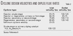
Cyclone velocities and dipleg mass flux rates should be reviewed to ensure that they are within acceptable ranges. Operating the cyclones within these conditions reduces the likelihood of catalyst losses by attrition or equipment deterioration. Table 2 lists design cyclone vapor gas velocities and dipleg mass flux rates.6
While not specifically discussed here, physical properties of the FCC catalyst play a critical role in minimizing catalyst losses from both the FCC regenerator and reactor.
Acknowledgments
Emery Udvari, Davison Catalysts Sales Manager, identified the need for this article. A special thanks goes to the re finers from whom we learn so much.
References
- Data published by the Energy Information Administration, Petroleum Supply Monthly, 1992-2001.
- Tenney, E., and Gardner, A., "Fluid Catalytic Cracking Cyclone Design and Modifications," Today's Refinery, October 1998, pp. 23-32.
- Private Communication with Edwin Tenney of Marsulex Environmental Technologies LLC, April 2001.
- Ewell, R. B., and Gadmer, G., "Design cat crackers by computer," Hydrocarbon Processing, April 1978, pp. 125-34.
- Wilson, J., "Fluid Catalytic Cracking Technology and Operation," Penn- Well, Tulsa, 1997, pp. 188-89.
- SadegHbeigi, R., "Fluid Catalytic Cracking Handbook," 2nd Edition, Gulf Publishing Co., Houston, 2000, p. 229.
The authors
David A. Hunt is a senior technical services representative for Davison Catalysts and is responsible for providing FCC technical service in the US. Hunt, who joined Davison in 1998, has 10 years of FCC experience focusing on process design, proprietary equipment technologies, troubleshooting, and catalysts applications. He holds a BS in chemical engineering from the University of Wyoming and an MS in chemical engineering from the University of Houston.
Gautham Krishnaiah provides FCC consulting and benchmarking through Davison Refining Services. His 15 years of experience in FCC includes commissioning, operation, troubleshooting, process design, licensing, and catalysts application. Krishnaiah, who joined Davison Catalysts in 1998, has a BS in chemical engineering from Osmania University and an MS degree in chemical engineering from Rensselaer Polytechnic Institute.
