Rig concept fills gap between light-mobile and heavy-stationary rigs
Workovers in deep directional gas wells push the limits of mobile rig capabilities. Sufficient rig capacity is not always available to perform the work safely.
ITAG Tiefbohr GMBH & Co. KG of Celle, Germany, has built and operated ITAG Rig 30, with performance capacities in the range between mobile and heavy stationary rigs.
With modern components and variable compact design, the rig is well suited for intended drilling and workover operations, giving special consideration to environmental protection, operational safety, and economic factors.
Natural gas demand and drilling technology advancement during the past 20 years have led to gas wells that are deeper, directional, highly deviated for extended reach, and sometimes even horizontal.
Occasionally, wells require workover for repair or remedial work. For economic reasons, speed of rig-up and rig-down, well location space requirements, among other factors, operating companies prefer mobile rigs.
Mobile rig derrick and substructures may function adequately for vertical gas wells, but beyond 4,000 m, workover requirements often exceed the performance limits of mobile rigs. As wellbores become directional longer casing strings and increased torque and drag place greater demands on the rig.
Challenging workovers with smaller rigs tax the limits of drawworks. Heavy operating conditions often require frequent slipping and cutting of the drill line. With increasing depth, mobile rigs may not have the setback capacity re quired to stand a string of pipe in the derrick.
Operators have performed workovers in deep wells with heavy-duty stationary rigs. Large well locations are required, however, and rig-up time and transportation costs are high.
Rig configuration
A new rig with improved capabilities and efficiencies was required for several planned workovers and well abandonments. Employees from BEB Erdgas und Erdöl GMBH, Hannover, along with ITAG worked together to determine the demands on equipment and define a new rig concept.
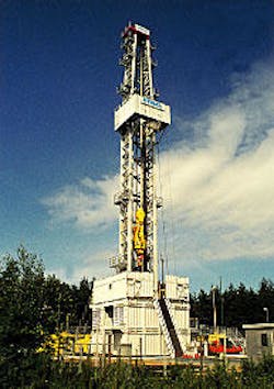
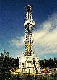
The resulting ITAG Rig 30, applying the latest technology, closes the capability gap between heavy-duty stationary rigs and smaller mobile rigs (Fig. 1).
With the integrated, compact, and modular design of the steel structure from Morinoak International Ltd. (MIL) of Great Yarmouth, UK, the rig is well suited to work where space is severely limited. The rig requires about 40% less space than a standard rig with the same capability, including the workshop, materials, and office containers.
Modular construction also allows the rig's footprint to accommodate producing wellsites, where the location of rig components must fit the wellsite's shape.
With the rig's hook load capacity of 2,500 kilonewton (kN), 562,000 lbf, it can work on highly directional wells and in horizontal wells down to 6,500 m (21,000 ft) deep. Also, the rig is capable of drilling wells to 4,000 m (13,000 ft), with an additional generator, mud pump, and more solids control equipment.
The new rig design features highly advanced systems and control technology for safe and environmentally compatible operations. The rig achieves high safety standards for personnel, especially with the use of sensors for monitoring travel ways and motion sequences, as well as rig floor facility remote control.
The rig thoroughly satisfies technical requirements imposed on modern drilling and workover rigs for operational safety, health, and environmental protection, as well as technical instructions specified for air pollution control and noise protection in Germany.
Substructure
The substructure consists of a box-on-box design, with four soundproof containers and three bridge elements. Engineers have designed the interior of the containers to accommodate machinery and other equipment.
The containerized substructure houses the drawworks, the cooling system for brakes and motors, the BOP accumulator closing unit, the central hydraulic system, the auxiliary winches for hoisting operations on the rig floor, and the service water supply system, among other facilities. The design protects vital components and reduces sound emissions.
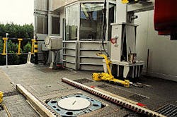
With a clearance height of 6 m, the substructure allows for installation of the required pressure rated blowout-preventer (BOP) stack. Crews can safely and efficiently handle preassembled BOP stacks, in the substructure, with a rail systems anchored to the floor and a BOP handling system.
The bridge elements of the substructure create the rig floor, with dimensions of 9 m x 9 m. These elements, open at the top, are essentially containers with integral soundproof walls. Rigs do not normally require protective walls on the rig floor.
A drainage system in the rig floor collects drilling fluid and waste water, for strict and effective control of effluents. The rig accommodates all supply and control lines in ducts under the floor.
Crews have little assembly work for rig-up and rig-down because the bridge elements are transported together with the equipment on the rig floor. Crews do not need to clear the rig floor for transport.
Derrick
The derrick can hold the 2,500 kN (562,000 lbf) rated hook load. At a total rig height of 51.6 m, the derrick can handle triples, which is a substantial advantage. This saves a great deal of time, especially for work in deep wells involving many round trips.
The rig floor has space to rack 6,500 m of 31/2-in. drill pipe or 4,000 m of 5-in. drill pipe. Racking pipe to only one side allows the driller's stand an unobstructed view of the borehole at all times.
Crews can adjust the height of the stabbing board from 3 to 17 m in the lower derrick area, which simplifies running of casing. The wide adjustment range of the stabbing board allows rig personnel to safely handle long casing lengths, as well as short drill string elements.
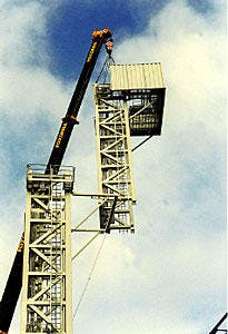
Vertical assembly of the derrick, in several sections with a telescoping crane, is an essential feature contributing to the efficiency of the rig (Fig. 2). The rig doesn't require an internal energy supply to erect the derrick and avoids the usual space requirement needed for horizontal derrick assembly.
Crews install the fingerboard at ground level and raise it together with the derrick section. The derrick segments connect together in the vertical position with pins.
For transport, crews fold the four derrick segments by means of hinges in the back, with the top drive rails remaining permanently installed in the segments. No further disassembly is necessary for the derrick to remain within dimensional limits for transport.
The traveling blocks hang on two chains below the mast crown for rigging down and rig transport. Rig personnel use an auxiliary line for quick reeving and unreeving of the drilling line.
Drawworks
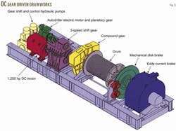
The manufacturer has equipped the rig with 1,250 hp DC gear-driven drawworks (GH-1250 EG), made by Wirth GMBH of Erkelenz, Germany (Fig. 3).
The drawworks operate with low noise and vibration. They have a proven track record for long service life and have been employed for many years in a wide range of applications, for example Royal Dutch/Shell Group's Prostar and Brent Charlie rigs.
Engineers designed the rig with the drawworks at ground level, in the substructure, allowing better vibration attenuation and soundproofing.
The drawworks allow for semiautomatic operation and regenerative braking, through a four-quadrant drive system (OGJ, Nov. 19, 2001, p 51). The system recovers energy from motion of the load and from the inertial forces during downward travel of the blocks. A gearshift optimizes speed, in correspondence with the load.
An anti-collision system (ACS) prevents inadvertent collision of the traveling blocks with the crown block or rotary table. The drawworks control system regulates acceleration or deceleration in the compound, in correspondence with the hook load and speed.
An eddy current brake and a mechanical disk brake serve as main brakes, acting directly on the drawworks drum. Both brakes are designed to operate at low noise levels.
An electrically powered automatic driller, integrated into the drawworks, acts positively on the drawworks drum. Engineers have designed it to be continuously adjustable, to allow drilling with constant weight-on-bit, with constant pump pressure, or with constant penetration rate, as required.
In the automatic driller mode, the drawworks can hoist hook loads of up to 1,600 kN (360,000 lbf) and can vary speed between 0 and 60 m/hr, compared to 2,500 kN in normal hoisting mode.
The automatic driller high downward speed is especially well suited for reaming operations. In case of emergency, the automatic driller can pull the drill string from the bottom of the hole.
Top drive
ITAG has equipped the rig with a VARCO TDS 9S electrical top drive unit, guided by a two-rail system integrated into the derrick.
Two three-phase AC motors provide 520 kw of drive power, which during sustained operation, can generate up to 45,000 N-m (33,200 ft-lb) of torque at 200 rpm. Frequency control of the drive system adjusts the speed.
The three-phase AC motors require no external ventilation through a hose line because of their encapsulated design. This reduces the service loop to the top drive to only the main power supply lines and control lines.
The hydraulic unit integrated in the top drive supplies the auxiliary hydraulic power for making-up and breaking-out the drill string joints, remote control of the kelly cock, and rotational and tilt movement of the elevator links.
Besides the electric motors, the top drive integrates several individual components, such as the rotary swivel, two kelly cocks, a make-up unit, and a pipe-handling system. The driller controls all top drive functions from the driller's stand.
The rig provides a 271/2-in. rotary table with auxiliary drive, for simplifying operational sequences and for supporting drill string manipulations, which occasionally becomes necessary.
Make-up equipment
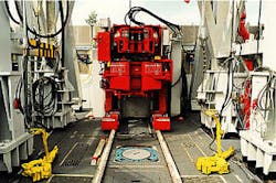
The rig employs a hydraulic roughneck, made by Norway's Maritime Hydraulics AS, for mechanizing the rig-floor operations (Fig. 4). Crews can connect drill string elements with uniform make-up torque, at high repeatable accuracy.
The driller operates the hydraulic roughneck at a safe distance from a control panel on the rig floor. The unit can handle pipe diameters ranging from 31/2 to 91/2 in.
With the hydraulic roughneck on the rig, crews use the manual rotary tongs for only a few exceptional cases. During such cases, however, a hydraulic cylinder system in the back of the derrick actuates the tongs. The central hydraulic system, installed in the substructure, supplies power to the make-up unit.
Driller's stand
The driller operates the entire rig from an enclosed driller's stand on the rig floor. The large window areas in the roof and walls of the driller's cab ensure an unobstructed view of the rig floor and fingerboard.
An air-conditioning system maintains an appropriate interior temperature at any time of year. Personnel in the driller's cab can communicate with various locations on the rig and with the tool-pusher's office, through an intercom system.
Three closed-circuit television cameras, selected individually for observation, monitor critical areas. The driller has a close-up view of the fingerboard, the zone between the fingerboard and rig floor (stabbing board), as well as the drawworks enclosure.
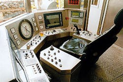
Engineers designed the driller's stand on the basis of model concepts and then optimized it in several steps, from an ergonomical standpoint (Fig. 5).
Ergonomics specialists considered the operating controls ease of access from the seated position, as well as the clear-cut arrangement of these controls. Designers located the most important control elements in the armrests of the driller's revolving seat and on the console within immediate reach of the driller.
Control, acquisition
The manufacturer installed a digital control and data acquisition system, in view of increasing demands imposed on measurement techniques and currently available methods for processing and presenting data.
The integrated programmable controller allows comprehensive monitoring of operating sequences during the drilling process. The driller's console easily displays vital information of the drilling process and machine facilities on-screen, as indicated by the instruments (Fig. 6).
The system provides trending for various operating processes, such as drill ing, circulation of drilling fluid, and running and pulling of drill pipe. Trending can highlight changes in drilling efficiency and impending problems in the borehole can be detected early.
Two of the video screens on the driller's stand provide continuous indication of drilling parameters as well as immediate information in the case of a malfunction. The driller can select various displays from a menu and preset alarm points for critical operating parameters. A third screen provides video observation.
During rig operations, the program control ensures that traveling equipment, such as the traveling blocks and top drive, do not collide with the crown blocks or rig floor.
The system calculates kinetic energy, considering the traveling block velocity and hook load, keeping operations safe at all times. If the traveling block's velocity gets out of control, despite this measure, the rig control system ensures immediate emergency braking of the drawworks.
Engineers designed the rig's digital control system and drawworks' anti-collision system to be mutually interlocking, to prevent equipment collisions on the rig floor.
The semiautomatic control option supports rig personnel and decreases the workload during operations. The system provides continuous assistance for monitoring the entire drilling process and displays data in the tool-pusher and operator's office.
The system continuously digitizes signals from sensors, indicates them on-screen, and processes and records them by the programmable controller. Comprehensive acquisition of drilling and operating data, allows engineers to reconstruct trends and variations, and perform evaluations after the fact.
The system records data on interchangeable storage media. When necessary, computers can reprocess relevant drilling data, for a given well, redisplaying the data for further analysis.
Mud system
ITAG Rig 30 operates with one or two mud pumps, as required by the operation, depending on whether it's working over a well or drilling a new well or well section. With 1,300 hp each, these pumps ensure adequate borehole hydraulics for either workovers or drilling operations.
The rig designers mounted the mud and charge pumps on a common frame to facilitate installation and transport. The tank unit incorporates the pump manifold.
With a volume of about 200 cu m (1,260 bbl), the tank facility provides sufficient capacity for deep gas well workovers.
Rig crews can increase tank capacity without difficulty, if necessary. The design of the piping system allows individual arrangement of the tanks, either in series or in parallel, as well as simple connection of additional tanks.
The outside dimensions of the tanks correspond with allowed transportation dimensions for European road traffic, and these limits are fully utilized.
Crews have complete access to the tank facility, with all gate valves, agitators, and solids-control equipment within easy reach through the flooring grates. The mud system employs submerged agitators of novel design horizontal impellers, for thorough mixing of the tank contents.
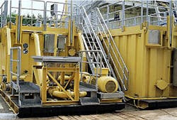
For the addition of drilling fluid materials from bags or small containers, the mud system uses a proven mixing system with an electronic balance, which allows addition of materials with minimal packaging waste (Fig. 7).
For solids removal, the system employs one or two efficient linear-motion shale shakers with an adjustable deck angle. During drilling operations, the rig also employs a solids-control system, consisting of a desander, desilter, and centrifuges, which are integrated into the circulation system as auxiliary equipment.
Additional components include mixing and transfer pumps, as well as a 2 cu m trip tank. Ultrasonic sensors monitor tank levels and indicate the contents, either individually or in total, on the tanks themselves and at the driller's stand.
Power station
High-performance, soundproof generating units supply power to the rig. Two or three Caterpillar 3508 Diesel engines, each with a power rating of 880 kw, power the rig as required depending on the demands of the opera tion and whether the rig is performing a workover or drilling.
Noise emissions are minimal because the engines are housed in sound proof containers. The engines are classified in the "low emission" category.
The engines optimize fuel consumption during all phases of operation, and the emission levels conform to the technical instructions on air pollution control in Germany, by an electronic engine management system.
Each diesel engine drives a 1,400 kv-amp three-phase generator. The electric power generated is supplied to a common bus bar in the power distribution container. The silicon controlled rectifier (SCR) system distributes power to various devices as direct current at variable voltage, or supplies power as three-phase current to the frequency control of the top drive.
The generators supply electric power to the auxiliary drive units by way of a further bus bar. The public power grid can also supply power to these drive units, if necessary.
Experience
The rig has performed 12 drilling and workover operations from June 1999 to May 2001, as follows:
- Plugged and abandoned 4 gas wells in depths ranging from 4,600 to 5,400 m.
- Drilled a reentry well to 3,400 m, partially in underbalanced conditions, with hole sizes of 81/2-in. and 57/8-in.
- Drilled two inclined "S-shaped" cavern wells with several cored sections and hole-opening operations to a depth of 1,450 m, with hole sizes of 24-in. and 171/2-in.
- Performed five workover operations in the depth range of 4,700 m, in part with difficult milling and fishing jobs.
ITAG Rig 30 has proven to be a reliable and convenient drilling and work over rig, even in difficult cases, based on the experience of these operations to date.
The rig performed difficult sidetracking and complex workover operations safely and effectively, with due observance of environmental protection requirements. Because of the precise and sensitive operating characteristics of the drawworks, the rig performed difficult and critical operations in the borehole reliably.
Modern rig technology and semiautomatic operating sequences relieve rig personnel by eliminating much of the tedious repetitive work.
For complex round trips, the driller operates tools and facilities on the rig floor from a safe distance. The stabbing board, which can be moved to 3 m above the rig floor, effectively supports these operations.
The rig requires only a small area for installation at the wellsite, due to the compact, integral design, and vertical raising mast. Crews can adapt the rig to existing well pad shape and size.
Rigid construction of the substructure containers allows for variable configuration of the rig, to accommodate various well cellars and foundations. Under full load, the rig can bridge a foundation spacing of up to 5 m in width.
The rig requires comparatively few transport units to move from one site to the next. The rig design offers a number of advantages, which are characterized by the various features:
- Compliance with environmental requirements.
- Excellent soundproofing.
- Low fuel consumption.
- Low exhaust emission.
- Ergonomic design of work areas.
- Assurance of safe operating sequences.
- Comprehensive instrumentation and data acquisition.
- Low space requirement for rig components.
- Small number of truckloads for rig moves.
- Short times for rig moves.
The author
Waldhorst Gutsche is drilling department quality assurance manager for ITAG Tiefbohr GMBH & Co. KG in Celle, Germany. He has worked for ITAG since 1979 and has been involved in the design, specification, and manufacture of drilling rig components. Gutsche has an MS in mechanical engineering from the University of Hannover and a PhD in petroleum engineering from the Technical University in Clausthal.
