New redox process successful in high-pressure gas streams

The new redox Sulfint HP process desulfurizes natural gas efficiently at high pressures. The process, developed by Institut Français du Pétrole (IFP) and Le Gaz Intégral (LGI) in association with Le Gaz Intégral (LGI), appears flexible and able to treat a wide range of gas compositions satisfactorily.
It was demonstrated under industrial conditions in a pilot plant operated for more than 6,000 hr, treating natural gas from an underground storage facility at Soings en Sologne, France.
Redox uses
Several technologies are available to extract H2S from gas or convert it into less-toxic compounds such as elemental sulfur. Among these are redox processes. Redox processes occupy a specific niche in which relatively small amounts of sulfur must be recovered (from tens of kilograms up to tons/day).
One current limitation of redox processes is their difficulty in treating high-pressure gases due to problems linked to solid sulfur particles in the aqueous redox solution used to treat the gas.
Despite some attempts, the direct treatment of gases at pressures greater than 500 psi remains challenging.1 2
This new process, however, has been successfully demonstrated under industrial conditions treating high-pressure (80 bara; 1,150 psia) natural gas.
The process can be operated without foaming, plugging, or periodic shutdown. Tests also have shown that the process is highly reliable and flexible with variable feed flowrates, H2S, and hydrocarbon contents.
Sulfint HP has been compared with a state-of-the-art scavenger technique (for an underground storage application) as well as with the known amine plus low-pressure (LP) redox process. The results show Sulfint HP costs up to 50% less than these processes in a fairly wide range of operating conditions.
Basic redox processes
In a redox process, gas is washed with a solution containing an appropriate redox catalyst. In a first step, the solution absorbs the H2S, which then reacts with the oxidized form of the catalyst to yield elemental sulfur as the catalyst is converted into its reduced form.
In a second step, the reduced form of the catalyst can be oxidized back by contact with air and reused. Redox catalysts usually are polyvalent metallic anions chelated with organic ligands.
The former vanadium salts used in the Stretford process have now been replaced in all major redox processes by iron (II and III) complexes.3 Most conventional ligands used are amino and polyamino polycarboxylic acids like EDTA, HEDTA, and NTA in an aqueous solution.
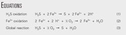
The Equations box shows the main chemical reactions involved in iron-based redox processes.
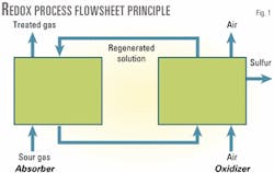
Steps 1 and 2 of the process are usually performed in separate vessels (Fig. 1). The redox solution is circulated alternately between the absorber and the oxidizer.
Absorption is performed at the pressure of the gas to be treated, which is usually greater than atmospheric pressure. The solution is oxidized by contact with air at atmospheric pressure.
The two steps are performed simultaneously in the same vessel when the gas to be treated contains oxygen or can be mixed with air, thus saving significant equipment costs.
Elemental sulfur forms almost instantly when the sour gas is contacted with the oxidized solution in the absorber vessel. This solid sulfur separates from the solution by decantation, flotation, or filtration. This is usually done after the reoxidation of the solution.
Redox advantages, limitations
Redox processes allow direct oxidation of H2S into elemental sulfur, at ambient temperature, with nearly 100% selectivity. Depending on the design of the absorber, conversions can be very high and reach virtually 100%. This leads to less than 1 ppm residual H2S in the treated gas.
The main limitations of current redox processes are their relatively high chemical costs, the quality of the sulfur produced (which is generally not as pure as Claus sulfur), and the difficulty of directly treating high-pressure gases.
The organic ligands used in the catalytic solution are slowly oxidized during process operation. This degradation, combined with catalyst losses with the produced sulfur, causes a continuous catalyst make-up.
The corresponding chemical costs are usually a few hundred US$/ton of sulfur produced. This chemical cost is one of the major components of the overall treatment cost, which, as a rough estimate, is below $1,000/ton of sulfur produced for redox processes.
This cost makes redox processes competitive for treating gases where the overall sulfur production is between about 100 kg/day and 20 tons/day.
Scavenging processes are more competitive for lower sulfur production. Their fairly high treatment costs (higher than $10,000/ton of sulfur produced) are compensated by a low investment cost and simplicity of process design.
For higher sulfur production, the amine plus Claus plant process is always the best choice because it exhibits-despite its complexity-a very low treatment cost (about $100/ton of sulfur produced).1
The sulfur obtained after physical separation from the redox solution is contaminated with the iron catalyst and the catalyst degradation products (mainly organic and inorganic salts).
It cannot, therefore, be sold as Claus sulfur.
It is possible to treat this sulfur to produce Claus-quality sulfur. But due to the low market value of sulfur, this solution is usually not worth considering.
The iron-based catalyst and its degradation products are nontoxic and easily biodegradable.
The "redox" sulfur can easily be disposed of in landfills or sold for fertilizer.4
The poor quality of the redox sulfur is another reason for not using redox processes when high amounts of sulfur are to be produced.
When high-pressure gases are desulfurized with a redox process, the aqueous redox solution leaving the absorber at high pressure will contain not only the elemental sulfur produced in the form of a suspension of very fine particles, but also a significant amount of dissolved gases.
Depressurizing this mixture before the atmospheric air oxidation step can cause severe foaming and plugging problems. Solid sulfur particles in the solution can also cause problems with the high-pressure pump needed to circulate the solution.
The most common way to desulfurize high-pressure gas, therefore, remains H2S extraction with an amine unit followed by a low-pressure redox unit treating the acid gas from the amine.
Despite these difficulties, the direct treatment of high-pressure gases with redox processes remains attractive. Studies show that up to 50% investment savings could be gained compared with the conventional amine plus low-pressure redox system.
Sulfint HP
LGI developed the Sulfint redox process in the late 1970s, and more than 12 units have been constructed. All are treating low-pressure gases.
One of the latest units, near Paris, is dedicated to biogas treatment. It has been operated by LGI for more than 6 years and has been useful in developing chemistry and sulfur cake recovery.
The process
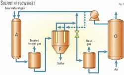
Fig. 2 shows the Sulfint HP process. The main innovation is the high-pressure filtration step to remove the sulfur particles from the redox solution before it is depressurized.
The catalytic system used in both the Sulfint HP process and the Sulfint process is based on well-known iron chelates chemistry in aqueous solution. The gas to be treated is admitted with the regenerated redox solution in Absorber A.
The absorber configuration used for the pilot tests consists of a cocurrent gas-liquid contactor filled with static mixer elements; other configurations could be considered, however, depending on gas flowrate and composition.
High transfer-rate static mixers allow the use of smaller, high-pressure absorber vessels. At the outlet of the absorber, the treated gas is separated from the reduced redox solution in a high-pressure drum. A water-wash section (not shown) is included in the upper part of this separator drum to remove any trace of catalytic solution from the treated gas.
The reduced catalytic solution loaded with sulfur particles is then filtered at high pressure in multicartridge Filter F.
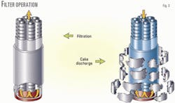
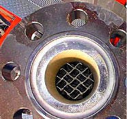
The specific design of the filter allows for continuous operation. Each cartridge is made of a flexible filtration cloth on a stiff support (Fig. 3).
The sulfur-loaded liquid flows from the outside of the cartridge through the filtration media, and the filtrate is recovered on the inside of the cartridge. The solid cake can easily be removed from the filtration cloth by sending a reverse flow of clear solution through the inside of the cartridge.
The cloth then expands, allowing the solid cake to break into pieces and fall to the bottom of the filter vessel.
In the filter vessel, the filtration cartridges are connected to form a small number of cartridge sets.
Each set of cartridges goes through periodic cake discharge with a clear solution under high pressure via the high-pressure pump (dotted lines of Fig. 2). This cake discharge does not interrupt the filtration on the other cartridge sets.
The sulfur cake pieces settle at the bottom of the filter vessel and are periodically removed through a depressurization chamber (not shown).
The filtered solution is recovered at the top of Filter F and sent to an expansion valve. From there, it goes to a flash drum where the flashed gas is separated from the low-pressure solution.
The low-pressure solution is then regenerated by contact with atmospheric air in Oxidizer Vessel O. The regenerated solution is pumped back to Absorber Vessel A.
The Sulfint HP flow scheme allows direct recycle of part of the high-pressure filtered solution to the absorber vessel (via a small circulation pump not shown in the figure). It is therefore possible to depressurize, oxidize, and pump back only the minimum amount of solution required by the stoichiometry of the reaction between Fe3+ and H2S.
High liquid loading can then be obtained on the static mixer elements in the absorber, at a minimum energy expense, thus avoiding sulfur deposits in the absorber.
Advantages
Continuous filtration of the solution before it is depressurized and oxidized offers many advantages compared to more-conventional flow schemes in which the sulfur is removed only after the oxidation step:
- Dissolved gas is easily separated from the liquid in the flash drum after the expansion valve, because the foaming tendency is reduced by the absence of fine sulfur particles.
- There is no risk of sulfur plugging downstream from the filter, thus allowing smaller downstream equipment such as the oxidizer vessel.
- The high-pressure pump that circulates the solution from the oxidizer back to the absorber is easy to operate because there can be no solid particles in the liquid that is pumped.
- The solution entering the absorber is clear, which reduces the risks of sulfur plugging.
- The possibility of recycling a significant part of the filtered solution directly to the absorber further reduces the risks of plugging (by sulfur formed in the absorber) by allowing high liquid loadings.
- Pumping costs are minimized because of this recycle. (Only the minimal amount of redox solution that is stoichiometrically required must be depressurized and oxidized, the rest of the liquid flowrate being kept under high pressure.) This is especially important for high-pressure operation.
- Sulfint HP uses well-known chemistry in aqueous solution. The use of an aqueous solvent significantly reduces the amounts of dissolved gases (compared to organic solvents) that would be flashed and lost after depressurization of the solution.
- The process has been shown during pilot tests to be highly flexible towards feed gas flowrate and H2S content variations.
Sulfint HP pilot tests
Pilot tests began in spring 1999 to prove the reliability of the Sulfint HP process with high-pressure natural gas, to confirm previous filtration-lab test results (at low pressure), and to obtain detailed data for the design of the industrial filters.
The filtration technology had already seen extensive industrial use, but its application for high-pressure filtration needed to be proven.
The flexibility of the process also needed to be studied under various feed conditions.
Several compounds (H2S, heavy hydrocarbons, mercaptans, etc.) were added to the fairly clean underground storage gas that fed the pilot unit. These additions took place during the second and third test runs.
The pilot plant was designed by IFP, built by LGI, and operated by IFP.
The Sulfint HP pilot plant is parallel to an existing desulfurization unit and treats a bypass flow of the gas that feeds this unit. The outlet gas from the pilot is then mixed with the treated gas from the desulfurization unit.
The pilot unit was designed between May and August 1998, and skids were delivered on site by the end of December 1998. The tests began in March 1999. The pilot plant was operated until the end of April 1999, when the gas production period ended.
Due to the operation mode of the underground storage, the pilot unit can only be operated during the winter when gas is being destocked. Second and third tests were conducted during winter 1999-2000 and winter 2000-2001.
Pilot plant
The pilot unit was designed to treat up to 1.7 MMscfd of gas at pressures up to 1,160 psia, containing variable amounts of H2S. The underground storage gas naturally contains 8-15 ppm H2S. Higher amounts can be tested by injection of additional H2S into the feed gas (second and third test periods).
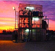
Fig. 4 gives an overall view of the pilot plant.
Previous papers described the pilot unit in detail.5 6 It consists of:
- An absorber (55 mm by 4 m) containing static mixer elements.
- A high pressure, gas-liquid separator drum. A wash drum (not shown) is installed downstream of the separator drum in to avoid entrainment of catalytic solution droplets in the gas.
- Two filters equipped with an industrial-size filtration cartridge. They are used and discharged alternately to simulate the actual operation of an industrial multicartridge filter.
- An oxidizer vessel with adjustable volume up to 50 l.
- All necessary pumps (mainly a circulation pump and a high-pressure pump that sends the regenerated redox solution back to the high-pressure loop).
- On line analyzers for H2S, pH, and redox potential of the solution.
- H2S and other additives.
Results; plant operation
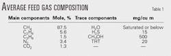
The pilot unit was operated during three winter test periods with a stable feed-gas composition. Table 1 shows the detailed average composition. The pressure was always about 1,160 psia and the feed-gas temperature about 25° C. During the first test period, the amount of H2S remained fairly stable at about 15 ppm by volume (ppmv).
During the second test period, pure H2S was added to the feed gas to obtain H2S levels between 8 and 5,000 ppmv.
During the third test period, toluene, octane, or a mixture of both were added to the feed gas to obtain levels corresponding to the saturation in the feed gas. An ethyl-mercaptan and an additive usually used as corrosion inhibitor in natural gas-production facilities were also injected into the feed gas during the third test period.
The pilot plant was operated 6,760 hr in the three test periods.
The operation of the pilot was always very smooth. There was no uncontrolled foaming in the flash vessel after depressurization of the solution, and the flash gas flowrate remained fairly stable between 0.75 and 1.5 l. of flashed gas per liter of depressurized solution.
There was no entrainment of redox solution in the treated gas, and no sulfur plugging at any point.
This last point was confirmed at the end of the three test periods when the different vessels were opened and inspected. (The low-pressure flash drum and oxidizer vessel are transparent and could therefore be examined continuously.)
There was a small layer of sulfur powder on the walls of the high-pressure separator drum, but there was no significant accumulation. Also, these small sulfur deposits were easily removed by gentle water washing.
Results of the first two test periods
During the first test period, the main goal was to establish the process feasibility. The pilot was therefore operated under fairly stable conditions for the longest period of time possible due to constraints of the underground storage operation.
This resulted in nearly 2 months of stable operation with corresponding H2S conversion above 99%. The treated gas H2S content was much below 1 ppmv. Details of this first test period are found in a previous paper.5
The second test period helped establish the high flexibility of the process and its ability to handle H2S levels up to 5,000 ppmv and a large range of gas flowrates.6
Results of the third test period
The third test period helped to determine the ability of the process to handle various feed gas compositions.
It was questioned whether the presence of heavy hydrocarbons or other impurities frequently encountered in natural gases might impact process operation. Would there be an increase in the foaming tendency of the solution?
The following components and mixtures, therefore, were added at various levels to the feed gas:
- n-Heptane.
- Toluene.
- A corrosion inhibitor often used in natural gas-production facilities and known to be a possible cause of foaming in amine plants. (This last compound is always injected in mixture with heavy hydrocarbons.)
Heavy-hydrocarbon injections corresponded to saturation levels and in some cases even exceeded this saturation level. These injections were performed at various gas feed flowrates and also various feed H2S levels; that is, in some cases heavy hydrocarbons, the corrosion inhibitor, and H2S were injected simultaneously.
In all cases, the process operation remained stable. Absorber pressure drop and H2S removal efficiencies were nearly unaffected. The high-pressure sulfur filtration also was nearly unaffected and in some cases was even slightly improved.
The only noticeable effect was an increase of the degassing time of the expanded solution in the flash vessel when very high amounts of corrosion inhibitor were added. This resulted in a higher foam level in the flash vessel. The amount of foam remained constant, however, and no flash gas was entrained in the oxidizer.
When the injected heavy hydrocarbons exceeded the saturation level, the formation of a liquid oil layer was observed at the top of the redox solution that settles in the high-pressure separation drum. This oil layer quickly disappeared after a reduction of the heavy hydrocarbons injection.
Under normal operations, such an accumulation would not occur because the gas is slightly superheated. This means that if liquid hydrocarbons should accidentally enter the process, they would not significantly affect its operation.
The impact of mercaptans was also investigated. Moderate levels of ethyl-mercaptan (about 12 mg/cu m) were injected into the feed gas without significant effect.
The ethyl-mercaptan level in the outlet gas was very close to the inlet level; therefore, with the catalytic formulation being used, no mercaptan removal could be expected. It also meant that the presence of mercaptans would not affect process operation.
Critical process equipment
No plugging was detected in the absorber during the tests, as can be seen from the pressure-drop measurements. The pressure drop, a function of gas and liquid flowrate in the absorber, was stable and fit well with the design correlations of the static mixer elements.
Visual inspection of the static mixer elements after the end of both test periods (Fig. 5) showed that nearly all elements were free of sulfur, even after operation at higher sulfur loadings during the second test period.
Only the first elements on top of the absorber showed small sulfur deposits on their external parts. These deposits probably can be attributed to a poor distribution of the liquid over the initial elements on top of the absorber.
These deposits completely disappeared after a few centimeters length. Furthermore, they are easily removed with gentle water washing. This confirms the idea that sulfur deposits can be avoided over the static mixer elements, provided that sufficient liquid loading is maintained.
The Sulfint HP flow scheme is a definite advantage in disconnecting the liquid flowrate feeding the absorber from the flowrate feeding the low-pressure oxidizer.
More than 80 kg of sulfur were recovered during the three test periods. Filtration times averaged about 36 hr, so that only 81 cake discharges could be carried out. This means that the installed filters could easily accommodate much higher sulfur loadings.
Cake discharge is fully automatic and started when the pressure drop across the filter reaches a specified value (about 1.5 bar; 20 psi). The filtration cloths did not need to be changed.
At the end of both test periods, after many filtration-discharge cycles, there were no signs of plugging. This is confirmed by the initial pressure-drop value, measured immediately after cake discharge.
This value remained near zero and did not increase after several cycles.
After the test, the filter cloths were only slightly yellow in color because of a few very fine sulfur particles.
Cost comparison
Accurate pricing of Sulfint HP units is possible because of the pilot tests. The tests compared state-of-the-art technologies used for high-pressure natural gas desulfurization, in the medium-size range (between 0.1 and 10 tons/day of sulfur).
The two following cases were considered:
- Underground storage application. In this case, corresponding to 0.11 ton/day of sulfur, Sulfint HP was compared with a nonregenerable solid scavenger process (activated carbon).
- Field natural gas production. In this case, corresponding to 0.1 to 10 tons/day of sulfur, Sulfint HP was compared with a combined MDEA plus LP redox process.
Methodology
Designs were compared for Sulfint HP, MDEA, low-pressure redox, and activated carbon (scavenger) units.
Investment and operating costs were calculated with the same methods for all processes.
Total desulfurization costs were calculated by adding the following:
- Duties: electricity, $0.034/kw-hr; gas, $1.50/MMbtu; steam (if needed), $5.70/ton.
- Chemicals: Both Sulfint HP and the LP redox were assumed to be at $383/ton of sulfur (except for the underground storage case for which higher specific chemical costs were allowed for Sulfint HP due to the small amount of sulfur).
This value seems too high for Sulfint HP, considering the actual catalyst degradation observed during pilot tests, but it is very close to what was used in previous cost studies where redox processes were compared with other technologies. It should be a conservative assumption. The MDEA cost was taken at $2.20/kg of MDEA.
- Manpower cost: A fixed amount was taken for both Sulfint HP and LP redox processes based on reported manpower for redox processes; it is a conservative assumption for Sulfint HP. Manpower cost (mainly for loading and unloading) was included with the activated carbon cost for the scavenger process. No manpower was allocated to the amine unit.
- Fixed costs: All cases were estimated at 7% of the battery limit investment.
- Capital depreciation: This cost was calculated on a 10-year basis at 6% interest.
Off sites, engineering, and process book expenses have not been considered. For the underground storage case, the units were designed to operate 2,850 hr/year. The field production case was designed to operate 8,000 hr/year.
Underground storage
The following feed gas characteristics were considered for underground storage:
- Flowrate: 165,000 cu m/hr; pressure, 100 bara (1,450 psia).
- Temperature: 20° C., H2S in, 20 ppmv (30 mg/cu m); H2S out, 0.6 ppmv (1 mg/cu m).
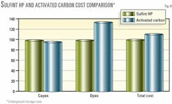
Fig. 6 shows results of the economic evaluation and how Sulfint HP is more cost effective than adsorption on activated carbon for underground storage.
The adsorption process investment is 5.1% lower than Sulfint HP, but the global treatment cost is 7.5% lower using Sulfint HP than adsorption. This is due to lower Sulfint HP operating costs.
Natural gas production
A lean natural gas was considered with the following composition (given in dry mole % basis, the gas being water saturated): CH4, 83.5%; C2H6, 3.6%; C3+, 1.1%; N2, 9.8%; CO2, 2.0%; and H2S, 120 ppmv.
Other factors were: gas flowrate, 250,000 cu m/hr (212 MMscfd); gas pressure, 100 bara (1,450 psia); gas temperature, 35° C. (95° F.); and outlet H2S specification, 3.5 ppmv.
The 2 mole % CO2 value is a level where CO2 removal is usually not necessary; therefore, the selective MDEA was chosen for the amine process in order to minimize its cost.
The total sulfur production in the base case is 1 ton/day.
Base case results
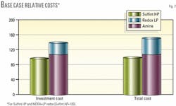
Fig. 7 compares costs of various processes.
In this case, Sulfint HP offers a significant cost reduction, the total desufurization cost being 54% higher with the conventional MDEA plus LP redox process.
Interestingly, Sulfint HP appears cheaper than the MDEA process alone, both in terms of investment and in operating costs. The amine reboiling and pumping costs largely exceed the chemical and pumping costs for Sulfint HP, resulting in variable operating costs for the amine twice as high as those for Sulfint HP.
Pumping costs alone are also twice as high for the amine process than for Sulfint HP.
This is due to the specific design of Sulfint HP, which allows only a minimal part of the total redox solution flow from the absorber to expand.
Parametric study
Alternate cases were defined with the same feed-gas composition, temperature, pressure, and outlet H2S specification.
Gas flowrates varied between 100,000 cu m/hr (85 MMscfd) and 250,000 cu m/hr (212 MMscfd). Sulfur production varied between 0.1 and 10 tons/day. H2S in the feed gas was between 15 and 3,000 ppmv. Cost correlation could be drawn from the base and alternate case pricing.
These correlations allow Sulfint HP to be compared with the MDEA process or with the combined MDEA plus LP redox process in a fairly wide range of H2S content and flowrates.
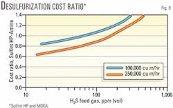
Fig. 8 compares costs between Sulfint HP and the MDEA alone. Total desulfurization cost ratio for Sulfint HP over the amine process is plotted as a function of the feed gas H2S for two feed-gas flowrates.
At 250,000 cu m/hr, Sulfint HP remains cheaper than the amine alone for H2S levels up to about 170 ppmv.
The economic limit between Sulfint HP and the amine alone process is reduced to about 70 ppm at 100,000 cu m/hr.
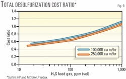
Fig. 9 shows similar comparisons between Sulfint HP and the global MDEA plus LP redox process. The comparison with global MDEA plus LP redox makes more sense than with the amine alone because the acid gas from the amine process must be treated to avoid toxic emissions.
Sulfint HP then remains cheaper to about 800 ppm H2S in the feed gas. At 250,000 cu m/hr, this corresponds to a sulfur production of 7 tons/day.
It is also interesting to note that the two cost-ratio curves at 100,000 and 250,000 cu m/hr tend to get very close. This means that the economic breakpoint between Sulfint HP and the MDEA plus LP redox processes can be expressed in terms of H2S concentration in the feed gas, nearly independent of gas flowrate. The breakpoint lies here between 650 and 800 ppmv.
At low-H2S contents, cost reductions with Sulfint HP can even reach 50%. This is in a range of sulfur output around 100 kg/day, where Sulfint HP has also proven to be competitive with solid scavengers.
Of course, the parametric study presented here is valid only for the feed gas composition and pressure defined. Higher CO2 levels in the feed gas (for cases in which CO2 removal is not needed) will favor Sulfint HP in an ever-wider range of H2S concentrations.
Acknowledgments
The partners of the Sulfint HP pilot tests, GDF, IFP, and LGI thank ANVAR and FSH (two French agencies which provide loans for the development of new technologies) who have supported this project.
References
- Leppin, D., "GRI's Program in Small-scale Sulfur Removal and Recovery-1997 Update," proceedings, 1997 Sulfur Recovery Conference, Oct. 12-15, 1997.
- Reicher, M., Niemiec, B., and Katona, T., "The Use of Aqueous Liquid Redox Desulfurization Technology for the treatment of Sour Associated Gases at Elevated Pressure," 1999 Sulfur Recovery Conference, Oct. 24-27, 1999.
- Buenger, C., Bedell, S.A., and Kirby, L.H., "Chelates in H2S Removal," 38th Laurance Reid Gas Conditioning Conference, March 1988.
- Buenger, C., and Morisse-Arnold, D., " Operating an Iron Redox Plant-Safety and Regulatory Considerations," Sulfur Recovery Conference, Oct. 12-15, 1997.
- Ballaguet, J.P., et al., "Direct H2S Removal from high pressure Natural Gas with the Sulfint HP Redox Process," Sulphur 99 Conference, Oct.17-20, 1999.
- Ballaguet, J.P., et al., "Pilot operating experience with a new redox process for the direct high pressure removal of H2S," 80th GPA Convention, Mar. 12-15, 2001.
The authors

Pierre-Yves Le Strat has been a process engineer for Gaz de France since 1998. He is in charge of gas treatment and technology for gas conversion. He received a degree in chemical engineering from Ecole Nationale Superieure des Industries Chimiques de Nancy in 1998 and spent 1 year at the University of Western Ontario, London, Ont.
Mathilde Cot has been a process engineer at Gaz de France since 2000. She had previous experience as a technologist at Shell (Berroise de Raffinage). Cot graduated from Ecole des Mines de Nancy, Energy and Process Engineering in 1999. She received a masters degree in refining, engineering, and gas from IFP-school, 2000.

Jean-Pierre Ballaguet is a senior research engineer for IFP at Solaize-France. He is in charge of gas desulfurization pilot tests for the IFP's development division. His past experience includes polymer development for electronic and structural applications, membrane technologies, and separation processes. Ballaguet is graduate of Ecole de Chimie de Toulouse, France (1978).

Jean-Louis Ambrosino is a senior research engineer in IFP's process engineering department at Solaize, France. He currently works on gas desulfurization. Ambrosino has 20 years' experience in development of gas, refining, and petrochemical processes. He began his career in the heat transfer department of Technip-France. He received a chemical engineering degree from University Poitiers, France, in 1980.
Christian Streicher is research and development project manager for IFP at Rueil-Malmaison, France. He has worked in process development at IFP since 1989, mainly in the areas of natural gas treatment, sulfur removal, and LNG. Streicher graduated from the Ecole Centrale de Paris in 1984 and also holds a PhD in environmental engineering (1989). He is a member of the GPA Europe.
Jean-Paul Cousin is a process manager with Le Gaz Intégral (LGI), Nanterre, France. He was formerly a process engineer with IFP and joined LGI in 1978. Cousin is a graduate of ESPCI and is an active member of AFG and of AFTP since 1981.