Tennessee terminals install wireless communication system
Installation of wireless technology at seven storage terminals around Knoxville, Tenn., has eliminated hardwired-phone circuit problems and recurring monthly phone costs and expanded the capability of exchanging more data between terminal and pipeline that can lead to safer operations.
The terminals installed a wireless system that reports tank alarms and can be configured to report gravity, flow rate, barrel count, and other useful data back to the terminals.
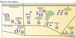
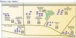
These terminals were faced with losing the copper-wire circuits used in communicating their grouped tank-level alarms to the supplier pipelines because of expansion on the nearby Interstate 40 (Fig. 1). The Knoxville Terminal Association, an organization of the local independent terminals that meets monthly to discuss safety, operations, and new technology, began searching for an alternate form of communication.
The telephone company had informed the association it had 8 weeks to find an alternate form of communicating their tank high-level alarms to the local pipeline companies. Research by the association of available options turned up only two choices:
- Replacing the phone circuits with radio modems that could transmit the data.
- Using new fiber optic phone circuits between the facilities.
Alarm reporting
Under CFR 195 Subpart F, the US Department of Transportation requires pipelines to operate with "procedures as necessary to provide a reasonable level of safety." Pipelines provide products to terminals with a tariff that outlines terms and conditions of the relationship.
One common safety system established between the pipeline and terminal involves reporting from the terminal to the pipeline of "Hi" and "Hi-Hi" (maximum fill) alarms to prevent overfill of the terminal's tanks.
The most common way terminals and pipelines communicate tank-level alarms is by hardwired copper phone circuits. Phone lines are used as physical circuits to indicate to the pipelines that the terminal tanks are at a safe operating level. The exactitude of the information transmitted is very critical for safe operations, for the environment, and for the public.
The Knoxville Terminal Association began to evaluate its task to replace the tank alarm system within only 2 months. Technology advancements had long surpassed the copper phone circuits as a way to communicate alarms to pipelines.
The association contacted Arseal Technologies LLC, Atlanta, to present the strengths and weaknesses of the following options:
- Conduit and cable or direct-burial cable to supplying pipelines.
- Dedicated four-wire multidrop modem options.
- Frequency shift keying (FSK) hardware options.
- Wireless remote-terminal units utilizing spread-spectrum technology.
The association settled on the wireless solution because of long-term cost benefit.
Spread spectrum
Spread-spectrum technology, first used during World War II, has continued to be used in US military and satellite communications.1 In 1985, the US Federal Communications Commission deregulated use of spread-spectrum technology into three frequency bands for commercial use. Bands in the 900 Mhz to 2.4 Ghz range are the most frequently used. The limit on transmission power is 1 w to prevent interference over long distances.
Since deregulation, spread-spectrum systems have proliferated in US. The technology and hardware have been and continue to be preferred for communication via radio because of their resistance to possible jamming and the unlikelihood of signal interception.
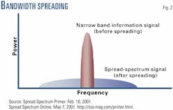
A spread-spectrum transmission contains a very wide band of frequencies with a very low power content and, hence, a much higher noise content. This much lower spectral power density allows spread-spectrum signals to occupy the same frequency band as conventional narrow-band systems, with little or no interference (Fig. 1).
As a comparison, an FM radio station's transmitted spectrum is a narrow band of frequencies with high-power content to enable long-distance transmission and minimize noise at the receiving end.
A spread-spectrum signal is distributed over a frequency bandwidth much wider than the minimum bandwidth necessary to transmit the original signal information. The spread bandwidth can be as much as 20-254 times the minimum. The excessive bandwidth is compensated by an effective increase in signal-to-noise ratio.
This is achieved by addition of a "pseudo-noise" (artificial noise) code into the RF carrier, which is synchronized and compared to the same pseudo-noise code at the receiving end. The spread-spectrum receiver will detect only signals with the same pseudo-noise code, which is what gives the spread-spectrum system its strong resistance to interference and interception.
There are, basically, four types of spread-spectrum modulation techniques: direct sequence, frequency hopping, chirp, and time hopping. Each technique is differentiated by how the pseudo-noise is applied to the system.
Many spread-spectrum systems used for digital data also use a cyclic-redundancy-check algorithm to detect errors in the received data and remove them before they reach the output. Missing data are reinserted from redundant information in the algorithm.
Spoofing and signal exploitations are the ability to listen and send false messages through a network. The inherent methods of spread-spectrum systems make them more secure, the level of security depending upon the manufacturer.
Some radio modems are configured so that they communicate with modems that are listed in their call book. Each radio modem checks its call book before accepting data from another source. If there is a match, the modem accepts the data and sends back a reply to the sender.
This added security allows a tank-alarm reporting system to report only real alarms, not false ones resulting from interference caused by other radio sources in the area. In addition, any confidential information exchanged between a terminal and a pipeline cannot be easily accessed by external sources.
Knoxville configuration
Any new system for the Knoxville terminals would require transmitting four grouped tank alarms to the two products local pipelines, Colonial Pipeline Co. and Plantation Pipe Line Co. Six of the independent terminals chose the wireless system: Williams Energy Services, BP Exploration & Oil Co., ExxonMobil Corp., Motiva Enterprises LLC, Conoco Inc., and Cummins Terminals Inc.
Designing the wireless solution required meeting two specific needs.
One request was to transmit the tank-level alarm data using wireless RF technology. The second requirement was that the two pipelines had to be on separate networks. In Knoxville, there are two pipelines and seven terminals using the wireless system.
The communication protocol in the network is standard ModBus RTU. The ModBus protocol limits each network to one master.
Each pipeline was configured as a master RTU that polls the seven local terminal slaves. The master unit utilizes a 5-db gain omni-directional antenna with a 900-Mhz modem. The slave units use two 900-Mhz modems with 6-db gain yagi directional antennas.
On the slaves, one modem communicates with Colonial and the other modem with Plantation. Requiring two modems at the terminal site does set hurdles for the system. Certain items must be taken into consideration during placement of two antennas near each other.
The power level can be too high when antennas are placed too close and may even cause the receiver to burn out. This problem is somewhat minimized because the terminals are using yagi-directional antennas.
Two additional actions could be taken at Knoxville to alleviate the problem, as recommended by the modem manufacturer.
The first recommendation was to mount the antennas with at least a 5-ft vertical displacement. The second recommendation was to place one antenna at a vertical polarization and the other at a horizontal polarization. This second recommendation was not implemented at Knoxville because there was some concern that the omni antennas at the master units might not receive the signal properly. We also minimized the transmitting power level on the slave unit whenever possible.
To date, there have been no relative problems arising due to the antennas being mounted near each other.
There are instances in which the pipeline and terminal modems will fail to communicate. This problem does not happen frequently but at the same time cannot be entirely avoided nor controlled.
The modems are configured to retry communications three times before moving on to the next node. It is relevant information for the terminals and pipelines to know when a communication failure exists. It is unnecessary to record these minor communication faults. In Knoxville, communication failures that persist for more than 30 sec are recorded.
These types of communication failure may result from power shortages, lightning strikes, or hardware failure. If a "comm. fail" occurs, the terminal's respective controller turns off the following:
- Group Oil Tank High Level Alarm.
- Group Oil Tank Hi-Hi Level Alarm.
- Group Gas Tank High Level Alarm.
- Group Gas Tank Hi-Hi Level Alarm.
- Communication Failure Output.
When communication is restored, the communication-failure output is turned back On at both locations. The terminal's tank-level alarm outputs return to their current status. The tank-level alarm outputs are normally On under good conditions. This "normally On" status provides fail-safe operating conditions for the system.
Benefits; limits
There are many benefits of a wireless system, including no cables, lower maintenance costs, no recurring monthly fees, and full duplex data exchange.
The most obvious benefit is that the system is wireless and requires little maintenance. And, because there are no third-party companies involved with the system, there are no recurring monthly costs or maintenance fees.
Telephone circuits can cost as much as $500/ month, including four phone circuits for the four tank-level alarms (oil and gas Hi and Hi-Hi level alarms) plus any maintenance fees. Traditionally, the only data passed between the terminals and pipelines are tank-level Hi and Hi-Hi alarms.
Because wireless systems use proprietary or standard communication protocols, the length of data that can be transmitted is variable. A wireless link that allows full data exchange between terminal and pipeline introduces a new safeguard for terminal-to-pipeline operations.
Here are some types of information that could be passed:
- Pipeline-to-terminal: gravity, flow rate, barrel count, and line wash count.
- Terminals to the pipeline: valve position, tank level, and line pressure.
Transferring this information between pipeline and terminal would ultimately reduce many operational errors.
For example, a terminal operator informs the pipeline that the terminal is ready to receive product into Tank A; the pipeline confirms the request and begins the delivery. But, when the terminal operator forgets to open the valve going to Tank A, the pressure begins to back up on the line and delivery is shut down. The pipeline calls the terminal operator to investigate what happened; both parties must file reports and start delivery again.
This unseen cost is a significant loss over time for both companies. Exchanging more information between terminal and pipeline can prevent such operational errors.
In the previous example, if the pipeline operator knew that the valve for Tank A was not opened, the operator could have advised the terminal operator and avoided the over pressure shutdown incident.
As with any other system, however, a wireless one has limitations.
The geographical topography and distance between locations have a major impact on the configuration of a wireless system and whether it is financially feasible.
Geographical topography influences the configuration because RF signals cannot penetrate mountains or earthen obstructions. Areas in mountainous terrain, valleys, and even in metropolitan areas with high buildings may create communication problems with a wireless system.
The normal solution is to use repeaters. This allows a master device to communicate to a slave device by repeating the signal over the obstruction. In some cases, a tower can be constructed to overcome obstructions. The maximum distance modems can communicate is 20 miles, line-of-sight.
Line-of-sight means that the modems are at the same elevation and pointed towards each other with no obstructions between. Distances farther than 20 miles can be achieved by use of repeaters. They allow master modems to communicate with other slave modems that cannot be accessed directly.
The number of repeaters that can be used within a single network of modems, however, can be limited, depending on the radio modem manufacturer. The number of repeaters allowed with the modems used in the Knoxville location is two. When geographical topography, local obstruction, or distance is an issue in installing a wireless system, careful study needs to be given to the costs and return on investment to justify practicability and payout.
Costs: wireless vs. others
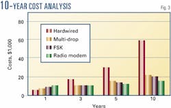
This section compares the costs of wireless technology with those of other conventional methods (Fig. 3). Typically, one of the following systems is used for communicating between locations:
- Hardwired phone circuits.
- Multi-drop modem systems.
- Frequency shift keying systems.
- Wireless systems.
Hardwire circuits
When pipelines and terminals introduced the concept of exchanging Hi and Hi-Hi level alarms to provide safer operations, hardwired phone circuits were used. In most terminal locations, a pair of wires is connected between the pipeline and the terminal. Voltage is sent out across the lines to hold up a relay at the pipeline representing the level alarm.
The benefits include having a hardwired connection to the pipeline, the ease of troubleshooting for a field technician, a single dedicated circuit for each alarm point, and minimal space used at the pipeline facility.
The disadvantages include aging circuits that require constant maintenance and frequent replacement, constant problems with phone service technicians disconnecting at junction boxes, limitations imposed by hardwired circuits and voltage drop on the lines, and limited data exchange.
Because the phone circuit installation has been primarily handled by the local phone company, installation costs to terminal are minimal. For monthly costs, the cost for four pairs to represent Hi level Oil and Gas and the Hi-Hi Oil and Gas can range from $200 to $500. Annual maintenance costs can be assumed at $300.
Calculating operational costs can assume the system will fail twice per year. This interruption requires a person to come out to complete the receipt and a technician to troubleshoot the failure and coordinate with the phone company. The cost on the terminal side could be as much as $2,500.
Multi-drop modems
Two-wire half duplex or four-wire full duplex modems with input-output (I/O) have extensive capabilities. Data can be passed to the individual terminals on a dedicated common phone line that allows for multi-drop communication configurations.
Benefits are that the system functions on hardwired and fiber optic circuits and that multi-drop modem equipment is readily available with various I/O options.
Disadvantages are that the system requires dedicated phone circuits, a single device at the pipeline facility for each connection, and a larger footprint at the pipeline location.
Installation costs run $7,500 for multi-drop installation for one terminal and one pipeline connection, which includes the multi-drop modems. Monthly costs for a four-wire dedicated circuit is $110, and maintenance costs can run $500/ year.
Calculating operational costs can assume that the system will fail twice per year. This interruption requires a person to come out to complete the receipt and requires a technician to trouble shoot the failure and coordinate with the phone company. The cost on the terminal side could be as much as $2,500.
Frequency shift keying
Frequency shift keying modems provide level alarms between the pipelines and terminals by passing a frequency for each input.
Benefits of the system include that is functions on hardwired and fiber optic circuits, its modem equipment is readily available, and it is easily tested with regular phone testing equipment.
Its disadvantages are that it requires dedicated units at the pipelines for each terminal, a much larger footprint than relays, and dedicated non-switched leased lines. The system also offers limited data exchange.
Installation costs for an FSK can run $8,000 for one terminal and one pipeline. This includes the FSK transmitter and receiver. Monthly costs can be estimated for two-wire dedicated circuit at $100/pipeline connection.
Calculating maintenance costs must assume an annual cost of $500. Calculating operational costs assume the system fails twice per year. This interruption requires a person to come out to complete the receipt and requires a technician to troubleshoot the failure and coordinate with the phone company. The cost on the terminal side could be as much as $2,500.
Reference
- Spread Spectrum Scene Online, http://www.sss-mag.com/, Articles: Spread Spectrum Primer, Introduction to Spread Spectrum & The ABCs of Spread Spectrum-A Tutorial
The authors
Genoveva A. Archuleta is the engineering leader at Arseal Technologies LLC, Atlanta. She has worked for several engineering firms, specializing mainly in the petrochemical and pipeline industries. Archuleta holds a BSEE from the Georgia Institute of Technology, Atlanta, and is a member of the IEEE.
Ramon Betancourt is a project engineer for Arseal Technologies. He worked 6 years for General Instrument Corp. and then joined Philips Electronics Manufacturing Technology as an applications engineer. He holds a BSEE (1992) from University of Puerto Rico and is a registered professional engineer in the Commonwealth of Puerto Rico.
Based on a presentation to ILTA Conference and Exhibition, June 12-14, 2001, Houston.


