Diverter valves enhance horizontal gravel packing
Gravel packing horizontal openhole laterals with washpipe diverter valves and external casing packers (ECPs) enables isolation of the produced oil stream from shale, water, gas, or other sections of the borehole.
The diverter valve allows selective gravel transfer in the lateral and prevents filling the annular space around the ECP. With an open annular space, one can inflate or actuate an ECP to form a positive mechanical barrier that isolates zones in a horizontal lateral.
Another benefit of this gravel packing method is the reduction in beta-wave (return gravel wave) placement pressure. The lower pressure enables one to gravel pack extended openhole horizontal wells and reservoirs with a low fracture gradient, such as are common in deep water.
Gravel packs
The industry has studied in detail the physical characteristics of gravel packing in horizontal wellbores over the past 10 years.
In the early 1990s, it developed the alpha and beta-wave model for predicting the sand deposition pattern in deviated wellbores. This model has been validated and refined in over 350 successful horizontal gravel-pack installations worldwide.
Openhole gravel-pack placement involves first installing a screen in the well across the productive interval and then mixing a highly permeable gravel or proppant in a carrier fluid that is circulated into the well to fill the annular space between the screen and the formation.
Specialized downhole tools facilitate wellbore stability, carrier-fluid circulation, and gravel-pack sand placement.
The tools provide a circulating path for the gravel slurry to flow down the workstring into the annulus below a packer and outside the screen. The screen retains the gravel, and the carrier fluid flows up the washpipe into the annulus above the packer and then to surface.
A complete gravel pack in the openhole-screen annulus provides a very stable, long-lasting downhole environment for producing only well fluids, not formation sand.
Although one can use both low and high-viscosity carrier fluids for gravel packing, a low-viscosity fluid, such as brine, is effective in achieving void-free openhole gravel packs.1
The pressure control concept discussed in this article only applies to gravel packs with low-viscosity carrier fluid.
Gravel packing with low-viscosity carrier fluid relies on high fluid velocity to transport the gravel-pack sand. In well deviations less than 55°, the combination of fluid velocity and gravity results in packing of the annulus outside the screen from the bottom up in a predictable pattern.
When well deviation exceeds 60°, the gravel deposition pattern changes such that the low side of the wellbore is packed first, followed by the high side.1-5 This type of deposition also has a predictable pattern.
In the first stage, the gravel-pack slurry forms a dune that grows in height. As the height increases, the slurry velocity increases and erodes the top of the dune, preventing further height growth. At this point, the dune propagates down the length of the well in what is commonly referred to as the alpha wave.
The alpha wave continues to propagate until it reaches the end of the screen, at which point the carrier fluid enters the washpipe and is circulated out of the well.
Also at this point, the beta wave or second stage of the high-angle gravel deposition begins.
The beta-wave propagates from the toe to the heel of the lateral, filling the remaining annular space outside the screen. The process diverts the carrier fluid into the restricted annulus between the screen and washpipe. From there, the carrier fluid is circulated out of the well.
As the beta wave moves towards the heel, the carrier fluid travels further in the annular space between the screen and washpipe, resulting in increased surface pumping pressure.
This greater pressure is a concern in openhole gravel packs in reservoirs with a low fracture gradient or in extended laterals.
Exceeding the formation fracture pressure will stall gravel deposition because of excessive fluid loss that reduces the slurry velocity in the annulus outside the screen.
Diverter valves
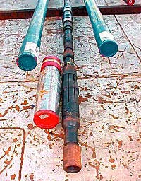
The diverter valve (Fig. 1) creates a gravel-free area around an ECP. The main valve components include the mandrel body, return port sleeve, isolation flapper, actuation spring, and bonded seals.
In addition to the valve, the method for obtaining a gravel-free annulus between the ECP and the formation involves understanding both the alpha and beta-wave phases.
During alpha-wave gravel deposition, one achieves a gravel-free annulus between the ECP and formation by sizing the unexpanded packing element OD to obtain an annular flow area that induces a slurry velocity at or above a 300-fpm critical transport velocity.6 The alpha-wave dune height at a critical transport velocity is effectively zero, resulting in no gravel being deposited in the annulus outside of the packer.
The alpha wave propagates around the screen above and below the ECP and essentially jumps over the packer to leave the void required for packer expansion. This method for creating a void does not restrict the number of ECPs in the well but does require a large enough packer OD to create a critical transport velocity
One requires a more complex solution to prevent gravel-pack sand deposition around the packer during the beta wave. The beta wave has to be stalled temporarily when it reaches the bottom of the ECP, before it continues above the packer.
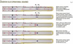
The technique requires one to alter the return flow path of the carrier fluid once the beta wave reaches the packer. Alteration of the return fluid flow path from the end of the washpipe into a diverter valve immediately above the ECP causes the beta wave to be discontinuous, preventing sand from covering the packer (Fig. 2).
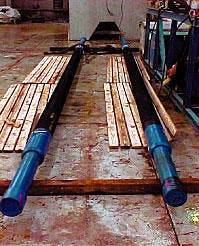
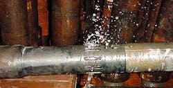
Testing this concept (Fig. 3) showed that whenever a diverter valve opened during the beta-wave phase, the carrier-fluid return path continually shortened. This meant that the carrier-fluid returns did not have to enter through the end of the washpipe, as in a normal gravel-pack operation.
The shorter flow path significantly reduces fluid friction pressure and correspondingly reduces pump pressure for maintaining the desired pump rate.
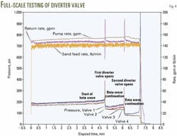
The output data from full-scale testing (Fig. 4) illustrates the pump rates and pressure reduction caused by the actuation of diverter valves in series.
This reduced pump pressure during the beta-wave deposition phase provides significant opportunities to expand horizontal gravel packing to longer openhole sections and in reservoirs with low fracture gradients.
The diverter valve design allows it to be an integral part of the washpipe string. The valve has bonded seals, similar to seals on a gravel-pack crossover tool, that seal off inside an ECP or polished bore receptacle (PBR) incorporated into the screen liner.
The bore through the valve is as large as possible, so as to reduce the backpressure created in the fluid return flow path. After one seals the valve inside the packer or PBR, an internal spring-loaded piston will sense differential pressure in the screen-washpipe annulus above and below the valve.
A differential pressure, in favor of the upper annulus, overcomes the spring force against the piston and causes the piston to move down to uncover locking dogs.
The process continues with the locking dogs moving radially outward to allow a power spring to drive the seal sleeve downward and expose flow ports.
This design eliminates the problem of sequencing valves by having the valve sense the screen-washpipe annular differential pressure across the valve. Only the lowermost valve sees the differential pressure when temporary screen-out occurs as the beta wave covers the screen just below the valve.
The valves, higher in the washpipe, do not see a differential pressure until further beta-wave deposition occurs.
Deepwater Brazil
Petroleo Brasileiro SA (Petrobras) has three completions in Brazil's Campos basin that have diverter valves and ECPs for establishing mechanical isolation in horizontal openhole gravel packs. It completed the three wells from a semisubmersible floating vessel and minimized risks by applying lessons learned from 36 prior successful deepwater, openhole horizontal gravel packs in the Campos basin.
The Marlim field well, 7-MRL-126HP-RJS, in 3,221 ft of water, was the world's first use of the diverter valve in a deepwater application. In this well, the producing reservoir is an unconsolidated sandstone with two lobes separated by shale.
Petrobras installed the diverter valve with ECPs in the lateral section to establish gravel-pack integrity, isolate a shale interval, and provide a barrier for future water shutoff in the lower lobe of the lateral section.
After the lower lobe of the reservoir waters out, Petrobras will set an isolation device in the blank between the ECPs so that oil production can continue from the upper lobe without producing high water volumes from the lower lobe.
Well specifics are as follows:
- 95/8-in. casing at 10,902 ft measured depth (MD) or 8,862 ft true vertical depth (TVD).
- 12,001 ft MD or 8,945 ft TVD well TD.
- 90.8° deviation.
- 10,903-12,001 ft openhole section.
- 11,549 -11,667 ft shale zone.
- 81/2-in openhole bit size.
- 51/2-in. 13-chrome openhole screen (6.54-in. OD).
- 51/2-in. ECP bodies (7.75-in. OD).
- 5-in. drill pipe.
- 0.64 psi/ft fracture gradient.
- 9.9-ppg sized carbonate system drill-in fluid.
- 9.8-ppg completion brine.
The first stage of completing the well involved generating a computa tional model and evaluating the hori zontal gravel-pack design. After determining the pump rate, the designers selected an ECP OD that would cause the solids transport velocity to be high enough to prevent gravel deposition around the ECP during alpha-wave placement.
Because the operations were from a floating vessel, the procedures required a balanced pressure and a weight set-down system for all tool positions to account for any rig movement at the surface.
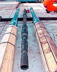
Service personnel checked and spaced out the diverter valves and ECPs prior to this equipment being sent to the rig. Fig. 5 shows the prejob spaceout for the ECP, indicating collets, and cup inflation tool. The work also included the installation of four diverter valves in a seal-bore test fixture and testing them by applying differential pressure to actuate the valves (Fig. 6).
Valve No. 1 tripped at 145 psi, followed by No. 2 at 145 psi, No. 3 at 135 psi, and No. 4 at 140 psi. Following the tests, the procedure included resetting and internally testing all four valves prior to shipment to the rig.
At the rig, knowledge of the shale section depth, 11,549-11,667 ft., was a critical factor for spacing out the gravel pack and washpipe assemblies.
The gravel-pack assembly consisted of:
- 9 5/8-in. SC-1R packer (rotationally locked).
- SC gravel-pack extension.
- Model A indicating coupling.
- Casing pup joint.
- Model A indicating coupling.
- Casing pup joint.
- 5 1/2-in. blank casing.
- 5 1/2-in. excluder screen.
- Indicating sub.
- 5 1/2-in. isozone inflatable packer.
- 5 1/2-in. blank casing.
- Indicating sub.
- 5 1/2-in. isozone inflatable packer.
- 5 1/2-in. excluder screen.
- Bull plug.
The job required that the open hole was circulated clean and displaced to brine.
Next, the process involved displacing the drill-in fluid from the casing and riser as in other previous openhole gravel-pack completions.7
The work placed the gravel-pack screens through both production lobes with inflatable ECPs located at the top and bottom of the shale section, with blank casing between these packers.
The assembly had a single, pressure-actuated diverter valve positioned to seal between the washpipe OD and the ID of the top ECP. The ECP OD was larger than the screen OD.
The gravel-pack slurry, pumped at about 8 bbl/min, had a 95% return rate. During the alpha-wave placement of sand, the process maintained the pump return rate to achieve critical transport velocity between the hole ID and the ECP OD to prevent sand deposition in each ECP annulus.
The diverter valve, after beta-wave sand placement over the lower reservoir lobe, sensed higher pressure above it than below it. This differential pressure tripped the valve port open above the seal and closed a flapper below it, allowing returns to enter the washpipe above the ECP. The flapper prevented any flow from entering the washpipe from below.
This caused the beta wave to skip over the packer OD and continue again, starting at the bottom of the upper screen section. Fig. 2 illustrates the process.
The service tool was pulled from the well after completing the gravel pack.
The next step in the process inflated the ECPs by running 5-in. drill pipe and the cup inflation tool into the well. Inflation volume, carefully monitored, can be correlated with the ECP packing element OD.
The measured inflation volume showed that both ECPs inflated to the expected 8.9 and 9.3-in. openhole ID. This indicates that the annular space between the packer OD and the formation ID was free of gravel.
Because of their direct contact with the openhole wellbore, the inflated packer elements will provide zone isolation when, at a later date, a plug is set in the packer ID or blank casing.
North sea application
In the North Sea, operators have completed five extended reach openhole horizontal gravel packs with diverter valves.
These diverter valves allowed operators to gravel pack extended lateral lengths while reducing applied pressure to the formation caused by beta-wave gravel placement. In addition, the valves improved gravel packing operations by reducing pumping time.
Openhole lateral lengths successfully gravel packed in the North Sea range from 3,096 to 6,943 ft, with reservoir depths of about 3,000 ft TVD. In these wells, conventional placement of the beta wave below formation fracture pressure is not possible without the diverter valve because of the relatively low fracture gradient of 0.659 psi/ft.8
Operators drilled and completed these wells with proven processes that included sized carbonate drill-in fluids, effective hole cleaning and brine displacement procedures, pressure balanced gravel packing systems to maintain hole stability, and a low-viscosity brine system for gravel transport.
These wells have 81/2-in., openhole lateral sections below 95/8-in. casing. The openhole laterals have 51/2-in. excluder premium screens, 6.32-in. OD. The screen assemblies include 4.400-in. ID PBRs that are spaced out along the screen liner length, as required for placement of the diverter valves in the washpipe assembly.
For gravel packing operations, the washpipe has a 4-in. flush joint and diverter valves that seal in the screen assembly PBRs. One determines the valve positions in the PBRs after positioning the gravel-pack crossover tool for gravel packing.
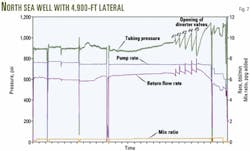
Operators have run 17 valves in the North Sea, with 2-5 valves/well with the purpose of keeping applied pump pressure below the formation fracture pressure. Fig. 7 shows data acquired for a well with five diverter valves opening in sequence as the beta-wave propagates from the toe to the heel of the lateral.8
Table 1 indicates that for both the North Sea and deepwater Brazil all the diverter valves, with the exception of one, functioned correctly.
For the valve that failed, analysis after the job strongly suggests that the valve failed to open because it was not spaced out properly to seal in the PBR, thus the valve did not sense the differential pressure required to open it.
Acknowledgments
The authors thank Baker Oil Tools and Petrobras for permission to publish this article.
References
- Penberthy, W.L. Jr., and Echols, E.E., "Gravel Placement in Wells," SPE Paper No.22793, JPT, July 1993, pp. 612-13 and 670-74.
- Maly, G.P., Robinson, J.P., and Laurie, A.M., "New Gravel Pack Tool for Improving Pack Placement," JPT, January 1974, pp. 19-24.
- Gruesbeck C., Salathiel, W.M., and Echols, E.E., "Design of Gravel Packs in Deviated Wells," SPE Paper No. 6805, JPT, January 1979, pp. 109-115.
- Dickinson, W., Anderson, R.R., and Dickinson, W., "Gravel Packing of Horizontal Wells," SPE Paper No. 16931, 62nd Annual Technical Conference and Exhibition, Dallas, Sept. 27-30, 1987.
- Penberthy, W.L. Jr., Bickham, K.L., Nguyen, H.T., and Paulley, T.A., "Gravel Placement in Horizontal Wells," SPE Paper No. 31147, SPE Formation Damage Control Symposium, Lafayette, La, Feb. 14-15, 1996.
- Larsen, T.I., Pilehvari, A.A., and Azar, J.J., "Development of a New Cuttings Transport Model for High-Angle Wellbores Including Horizontal Wells," SPE Paper No. 25872, SPE Rocky Mountain Regional Low Permeability Reservoirs Symposium, Denver, Apr. 12-14, 1993.
- Mathis, S.P., et al., "Horizontal Gravel Packing Successfully Moved to Deepwater Floating Rig Environment," SPE Paper No. 56783, SPE Annual Technical Conference and Exhibition, Houston, Oct. 3-6, 1999.
- Coronado, M.P., Corbett, T.G., "Beta Wave Pressure Control Enables Extended-Reach Horizonal Gravel Packs," SPE Paper No. 71668, SPE Annual Technical Conference and Exhibition, New Orleans, Sept. 30-Oct. 3, 2001.
Based on a presentation at Deep Offshore Technology, Rio de Janeiro, Oct. 17-19, 2001.
The authors
Eugene E. Ratterman is manager of the deepwater development group for Baker Oil Tools, Houston. He previously worked for Exxon Co. USA as a completions-production engineer. Ratterman holds BS and MS degrees from the University of Louisville.
Leo E. Hill Jr. is a senior application specialist for Baker Oil Tools, Houston, specializing in preparing business cases and marketing feasibilities. He has a BS in business administration from Texas A&M University.
Jeff Knippa is a senior applications engineer for Baker Oil Tools, Houston. His expertise includes openhole completions involving external casing packers. He has a BS in mechanical engineering from the University of Texas at Arlington.
Fernando Antonio Machado is a well completion designer for Petroleo Brasileiro SA (Petrobras) in Macae, Brazil. He is responsible for the completion and workover programs in Marlim field. Machado is an SPE member.
Agostinho Calderon is a petroleum engineer for Petroleo Brasileiro SA (Petrobras) in Macae, Brazil. He coordinates and evaluates the performance of sand control operations.


