Unusual design considerations drive selection of Sakhalin LNG plant facilities
Plans are under way for an LNG plant, the second phase of the Sakhalin-II LNG project on Russia's Sakhalin Island. First LNG will be delivered to customers in 2006.
A consortium consisting of OAO NIPIgaspererabotka (Russia), Chiyoda Corp. (Japan), and Fluor Daniel (the Netherlands) last year was awarded a contract to provide engineering services for the preparation of the project specifications and the technical and economic substantiation (TEO) documentation for the project required under Russian Law.
The new air-cooled LNG plant will have two trains with a capacity of 4.8 million tonnes/year each. The processes employed are the Sulfinol-D process for acid-gas removal and the Shell Double Mixed Refrigerant (DMR) process for liquefaction. The latter process allows maximum flexibility to cope with changes in feed gas and the wide ambient temperature range, while at the same time having low fuel consumption.
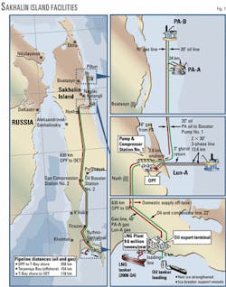
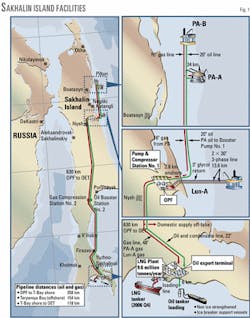
Sakhalin Energy Investment Co. was established in 1994 to manage the Sakhalin-II project. That project includes two significant fields, Piltun-Astokhskoye, an oil field with associated gas, and Lunskoye, a gas condensate field located 12-15 km (7.5-9.5 miles) off the northeast coast of Sakhalin Island (Fig. 1).
The combined recoverable hydrocarbon resources of these fields are about 1 billion bbl liquids and 18 tcf of gas.
In June 1994, Sakhalin Energy signed a production sharing agreement (PSA) with the Russian party (Russian Federation and the Sakhalin administration) and received a license to develop the fields. Work began in June 1996.
The company decided to use a phased-development approach and took advantage of an existing ice class mobile drilling rig, Molikpaq, for the first phase of the project.
This accelerated the project schedule to 3 years from 4 years. The result-the Vityaz production complex-was installed at the Piltun-Astokhskoye field in September 1998 and produced Russia's first offshore oil in July 1999.
The Vityaz production complex, centered on the modified Molikpaq drilling-production platform, contains facilities for production and tanker offloading during the area's 6-month, ice-free season. These facilities include a subsea pipeline, a single-anchor-leg mooring system, and a floating storage and offloading facility.
The full development of the Piltun-Astokhskoye and the Lunskoye fields will take place in the second phase of the Sakhalin-II project. Sakhalin Energy expected to submit this plan to the Russian party in mid-2001.
The size of the Phase 2 project will be almost an order of magnitude larger than Phase 1, with a total investment of around $8 billion.
This phase includes offshore production facilities, upstream gas-conditioning facilities, oil and gas-transmission lines to the south of Sakhalin island, an oil-export terminal, an LNG-production terminal, and LNG shipping (Fig. 1).
Ownership of Sakhalin Energy changed in December 2000. Shell Sakhalin Holdings BV and Marathon Sakhalin Ltd. completed an exchange agreement whereby Marathon's 37.5% interest in Sakhalin Energy was transferred to Shell. In addition, a further agreement was signed between Shell and Mitsubishi under which 7.5% of Sakhalin Energy's shares were sold by Shell to Mitsubishi.
The new shareholding structure of the company is now Shell 55%, Mitsui & Co. Ltd. 25%, and Mitsubishi Corp. 20% (Diamond Gas Holdings BV).
LNG facilities
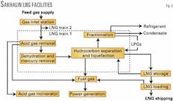
The Sakhalin Energy LNG project involves the development of a new greenfield base-load LNG plant, in Aniva bay on the south side of Sakhalin island. The two LNG trains will have gas treating, liquefaction, and fractionation facilities with a common gas-inlet station, supporting utilities, and LNG export terminal (Fig. 2).
Inlet, gas-treating facilities
Gas from the upstream processing facility (some 1,500 MMscfd) arrives via a 630 km, single-phase trunkline at the plant gas-inlet station. This unit has a pig receiver and inlet separation vessels to remove any possible dust or traces of liquid.
The gas is pressure controlled before being routed to the inlet of each of the LNG trains. The unit also can supply start-up fuel gas.
In each LNG train, feed gas is first passed through the acid-gas-removal unit to remove all CO2 and trace H2S (Sulfinol-D process) to prevent solidification during liquefaction and to meet the LNG product specification.
The rich solvent is preflashed and then stripped in a low-pressure regenerator column, using heat-transfer fluid (HTF) as heating medium. Flash gas is recompressed to feed-gas pressure and reinjected upstream of the absorber. Acid gas, containing some hydrocarbons coabsorbed by the solvent, is routed to an incinerator.
Following acid-gas removal, the gas is dehydrated, first by chilling with precooled mixed refrigerant (PMR) to condense the bulk of the water, and second by being passed over molecular sieve beds for deep removal of the water to well below 1 ppm(vol).
A three-bed arrangement was selected, with two beds in adsorption mode and a third in regeneration mode. Regeneration of the molecular-sieve beds is achieved by a slip stream of dehydrated gas, heated with waste heat from the gas turbine driving the PMR compressor.
After cooling and water removal, the regeneration gas is compressed back to the main feed stream, upstream of the PMR chiller.
Elemental mercury from feed gas can cause rapid corrosion of aluminm in cryogenic heat exchangers. Therefore, a mercury-removal unit was installed downstream of the dehydration unit, consisting of a single guard bed of sulfur-impregnated activated carbon.
Liquefaction
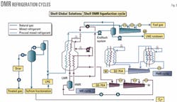
The Shell DMR process was selected for liquefaction. This process uses two separate mixed-refrigerant cooling cycles, one for precooling the gas to about -50°C. (PMR cycle) and one for final cooling and liquefaction of the gas (MR cycle; Fig. 3).
Following dehydration and mercury removal, the treated gas is further cooled against PMR and fed to the scrub columns. The scrub columns remove heavy hydrocarbons (C5+) that could freeze out in the cold part of the cryogenic heat exchangers and recover refrigerant components for make-up to the two refrigeration loops.
The bottom product of the scrub columns is fed to the fractionation unit. Reflux to the scrub columns is generated by condensation of part of the overhead gas against PMR. The scrubbed gas is recombined with excess NGLs from the fractionation unit and fed to the cryogenic heat exchangers for further cooling and liquefaction.
In the cryogenic heat exchangers, the natural gas is liquefied and subcooled to about -153° C. Subsequently, the LNG is reduced in pressure in a liquid expander and flashed in the end-flash vessel, achieving a temperature close to the atmospheric boiling point (about -161° C.). End-flash gas is routed via an end-flash exchanger to a three-stage end-flash compressor where it is recompressed to fuel-gas pressure. LNG is pumped to LNG storage.
Refrigeration cycles
A mixed-refrigerant system precools the natural gas, NGL reinjection streams, and liquefaction mixed refrigerant at two pressure levels. This precool mixed refrigerant (PMR) consists of a mixture of components, predominantly ethane and propane.
PMR vapor from the precool exchangers is routed via knock-out vessels to a two-stage centrifugal PMR compressor. Desuperheating, condensation, and subcooling of the PMR is achieved by induced-draft aircoolers. The PMR compressor is driven by a single gas turbine equipped with an electric starter motor-generator.
A second mixed-refrigerant cooling cycle (MR cycle) provides the cooling duty for the liquefaction of the natural gas. The refrigerant of this cycle is a mixture of nitrogen, methane, ethane, and propane. Mixed-refrigerant vapor from the shell side of the main cryogenic heat exchanger is compressed in an axial compressor followed by a two-stage centrifugal compressor.
Air cooling provides intercooling and initial desuperheating. Further desuperheating and partial condensation are achieved by the PMR precooling cycle. The mixed-refrigerant vapor and liquid are separated and further cooled in the main cryogenic heat exchanger, except for a small slipstream of vapor MR, which is routed to the end-flash exchanger.
Both mixed-refrigerant cycles are driven by a single gas turbine equipped with a separate variable-speed starter-helper motor.
Fractionation
The fractionation unit extracts refrigerant components for the PMR and MR cooling cycles and produces stabilized condensate from the NGLs that are separated in the scrub columns.
The unit consists of four columns in series: demethanizer, de-ethanizer, depropanizer, and debutanizer. Light components not used for refrigerant are reinjected into the LNG. Stabilized condensate is routed to the neighboring oil export terminal.
LNG export facilities
LNG is pumped to two 100,000-cu m LNG storage tanks from the end-flash vessel in each LNG train. LNG is stored at almost atmospheric pressure. Heat inleak creates boil-off gas which is recompressed and used as gas-turbine fuel.
Cooling facilities
The heat generated in the PMR and MR cooling cycles is rejected from the process by air cooling. This was selected over water cooling for several reasons.
Aniva Bay is shallow and subject to relatively large temperature variations due to local currents. To reach sufficient depth, long water-intake lines would be required. In addition, there are environmental drawbacks of seawater cooling. Both air and water cooling require special design provisions for winterization. Any failure in winterization is expected to cause only partial loss of cooling in case of air cooling. Furthermore, air cooling would be lower cost.
Heating facilities
Heat is required all year in the NGL fractionation process and Sulfinol treatment of the feed gas. Other uses are heating of buildings and plant winterization.
Options for heating were steam, water-glycol, and hot oil, while the key selection criteria were operational considerations and maximization of waste-heat recovery.
A heat-transfer fluid (HTF) is preferred because it is a low-pressure closed system that can be designed with heating loops of different temperature levels. Another benefit is that an HTF can be selected that has a pourpoint below the minimum ambient temperature, contrary to steam.
A water-glycol mixture has the disadvantage of higher system pressure than heat-transfer fluids. Also, the heating system would be restricted to a single, low-temperature loop. Consequences of a possible leak from a high-pressure, water-glycol system are more serious, because water would ingress into the process.
Electrical heat is required for instrument winterization and specific duties required during shutdown periods.
Selecting acid-gas removal process
An acid gas-removal process is selected from a range of criteria. The required solvent circulation rate to meet the treated-gas specification and the specific heat required for solvent regeneration are important because these factors directly affect the capital and operating costs of the process.
A proven high reliability and availability of the treating process are essential for application in baseload LNG plants. In the case of Sakhalin LNG, the feed gas contains less than 0.8 mole % CO2 and less than 20 ppm mole of H2S.
Because of this, application of tertiary amine solvents, which are advantageous at high-CO2 concentrations because of potentially high solvent loading, was found not to provide special benefits. The Sulfinol-D process was selected with this in mind and based on the following factors:1
Selecting liquefaction process
A process comparison was carried out in 1998 to ensure that the most cost-effective liquefaction process would be applied, especially taking into account the ambient conditions at Sakhalin.
The Propane Precool Mixed Refrigerant (C3/MR) process (Air Products & Chemicals Inc. license) was compared with two other commercially viable processes. The C3/MR process, applied in all Shell-advised LNG plants around the world, was originally selected as the basis for the liquefaction design.
This process is generally accepted to be the most cost-effective and reliable baseload LNG process available and covers nearly 90% of the total installed worldwide baseload LNG capacity since 1972.
The other processes selected for the comparison were the Cascade process and the Shell Double Mixed Refrigerant process (DMR). An optimized version of the Cascade process (Phillips/Bechtel license) has been applied in the Atlantic LNG project in Trinidad, and it is the only process that is being used in an arctic climate (Kenai LNG).
The DMR process as developed by Shell has two mixed refrigerant loops: a two-stage precooling cycle and a single-stage MR cycle.
The DMR process was selected on the basis of highest plant efficiency and, accordingly, the highest production capacity for given mechanical driver power, and the lowest specific cost.
Flexibility of the DMR process
The low average ambient temperature at Sakhalin enables high gas-turbine power availability and high LNG-production capacity. The LNG process designer, however, must optimize the LNG production capacity for the whole range of possible feed-gas compositions and ambient temperatures.
Inherent in the use of gas turbines as mechanical drivers for the refrigerant compressors, the available refrigeration power changes with ambient air temperature.
Because of the air cooling applied, the ratio of power required for the different refrigeration cycles also is significantly affected. The range in feed-gas composition is not exceptional for the Sakhalin LNG design, but the range in ambient air temperatures is.
With a design temperature variation of 45° C. to cover both summer and winter conditions, this range is roughly twice that typically encountered for tropical LNG plants.
Shell's designs for modern baseload LNG plants can utilize the total installed mechanical driver power. In the C3/MR process, the power required for propane precooling is less than for the MR cycle. The ratio is roughly 40:60 for air-cooled units.
So that all installed gas-turbine power can be fully used, a motor-generator is installed on the GT compressor train of the propane cycle, and a helper motor is installed on the GT-compressor train of the MR cycle. This allows shifting of excess power from the propane to the MR cycle with maximum control flexibility (MLNG-Tiga design).2
The DMR process provides the required additional flexibility to maximize LNG production over the wide range of ambient temperatures and feed-gas compositions encountered at Sakhalin.
Making the PMR refrigerant composition lighter enables the refrigeration duty to be shifted from the MR to the PMR cycle, keeping both gas turbines fully loaded and thereby maximizing overall LNG production.
Since the original studies from which the Shell DMR process was selected, further process optimization has increased the LNG production capacity to 4.8 million tonnes/year/train (based on 332 productive days/year for the system during the first years).
Specific power of DMR process
The specific power is a benchmark to evaluate the thermodynamic effectiveness of a liquefaction design to produce LNG. It is expressed as kw shaft power for liquefaction only, per ton/day of LNG rundown to the storage tank.
For a C3/MR design, therefore, it is the total of the propane, mixed refrigerant, and end-flash compressor powers over the LNG rundown/stream day to the LNG tanks. For the DMR design, propane compressor power is replaced by precool mixed-refrigerant compressor power.
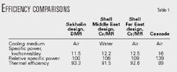
Taking into account the efficiency of the gas-turbine drivers, one arrives at the overall thermal efficiency. This is expressed as HHV products/HHV of feed. Table 1 indicates the Shell DMR process has the highest efficiency.
A low specific power may be achieved in two ways:
- The efficiency of the process.
- The efficiency of the compressors.
The process efficiency is measured via the exergy loss in the heat exchangers, compressors, gas turbines, etc. Exergy loss can be considered as the loss of useful work (i.e., compressor power that is not converted into cooling of the natural gas).
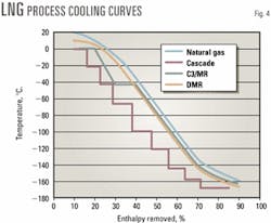
An efficient process minimizes exergy losses. An indication of exergy loss is the area between the cooling curves of a process. Fig. 4 shows cooling curves of LNG processes.
The figure illustrates the ability of the Shell DMR process to tailor the mixed refrigerant in both cycles and thus minimize the area between the cooling curves. Both the C3/MR and the Cascade process have less flexibility (C3/MR only in the final cooling).
The large refrigerant flows in the MR cycle enable the use of highly efficient axial compressors. These compressors have an efficiency of 6-8% higher than centrifugal machines.
Large gas-turbine drivers like General Electric's Frame 7s also result in more-efficient conversion of fuel gas into driver power. Furthermore, the waste heat of the precool gas turbine is used for process duties, thus avoiding the need for separate furnaces.
Designing for Sakhalin conditions
Air cooled, gas turbine-driven C3/MR plant design for tropical conditions is now considered to be at a mature stage following the start-up of the first air-cooled plant in the Australian North West Shelf project in 1988.
There have been many improvements made in more-recent projects that successfully resulted in reducing the plant specific cost.3
These cost-saving measures have been included in the Sakhalin design. When compared with a tropical design, however, some of these savings will be lost due to the requirement for winterization.
Although not a truly arctic climate, the yearly average temperature is only 3° C., with an extreme low of -33° C. and high humidity with significant snowfall in winter.
Additional costs come from the following:
- Enclosed compressor houses for maintenance.
- Design for ice load conditions.
- Winterization of air coolers to prevent excessive cooling and liquid formation in the refrigerant streams and freezing of water-containing streams in the treating units by heat transfer fluid.
- Control of air flow by variable-speed drives to prevent excessive cooling. (Air coolers are designed for summer conditions.)
- Extensive heat tracing of the piping.
- Protection of compressors and recycle valves against liquids.
- Buildings around water-treating units.
- Winterization of air inlet systems on air compressors and gas turbines.
References
- Klinkenbijl, J. M., Dillon, M. L., and Heyman, E. C., "Gas Pre-treatments and their impact on Liquefaction Processes," GPA Annual Convention, Nashville, Tenn., Mar. 2, 1999.
- Ismail, N. H., and Grootjans, H. F., "The MLNG-TIGA project," LNG 12, Perth, May 4-7, 1998.
- McEwan, M. W., Ellison, G., Punt, A., Nagelvoort, R. K., Senden, M. M. G., "Unlocking offshore gas reserves by cost effective LNG and gas to liquids schemes," Mediterranean Offshore Conference, Alexandria, April 2000.
The authors
Wim Dam is a principal technologist in the LNG and gas processing group of Shell Global Solutions International, The Hague. He joined Shell in 1981 and has held several positions in gas treating R&D and gas processing design. In 1990, Dam was seconded to Woodside Energy as a technologist at the North West Shelf LNG plant in Australia and in 1994 as technology manager at the Malaysia LNG plant in Bintulu, Sarawak. Since 1997 with Shell Global Solutions, his responsibilities have included design and development of LNG processes, design of LNG storage and loading facilities, and technological, operational, and start-up advice to gas processing and LNG companies. Dam holds an MS in physical chemistry from the University of Leiden, the Netherlands.
Siew-mung Ho joined Woodside Energy in 1991 following graduation in chemical engineering at Adelaide University, Australia. She worked as a technologist on the North West Shelf LNG plant, before moving into the commissioning and start-up of the third train expansion. After further experience in petroleum engineering and facilities engineering, Siew-mung returned to the North West Shelf LNG plant as a process control technologist. In 1999, she was seconded to Shell Global Solutions International in the LNG and gas processing group, based in The Hague.
Working with Russian statutory regulations
A good understanding of Russian codes and standards will prevent rework and delay of a project schedule at a later stage.
The ability to move a design forward to an "approval for construction" stage for Russian authorities is essential. Therefore, Russian participation is important in awarding the engineering services contract for preparation of the project specifications and the technical and economic substantiation (TEO) documentation for the project, as defined under Russian law.
Russian regulations indicate two stages of project development:
- A predesign or preproject stage. This involves early stages of project planning and development of the investment feasibility study. This is called the TEO of Investment.
- A project implementation stage, which involves the development and submission to Russian authorities of design and construction documentation (TEO of construction, or TEOC) for their review and approval.
The LNG plant and LNG-export terminal are subject to a separate section of the Sakhalin-II TEOC. Approval is obtained by submission of all the required project documentation to the "Glavgosexpertiza" (a department of the Ministry of Construction), which coordinates the review of the TEOC through all the ministries concerned.
The scope of such a TEOC is extensive and covers all stages and aspects of the project, including organization of construction, facilities design, environmental impact assessment, risk assessment, and emergency response. It also includes the later production and company management, labor arrangements and conditions, and safety of personnel.
The preparation of the TEOC requires knowledge of literally thousands of codes and standards.
Russian regulations require significant detail to be available at the time of review, including, for example, vendor selection, which in Western project handling would only be known at the time of the EPC phase of the project.
To handle situations of noncompliance, or in case no Russian regulations exist, it has been agreed with the authorities that so-called project specific technical standards (PSTS) will be developed. Such PSTS will be scrutinized by Russian scientific institutions and, if in agreement, will be accepted by regulatory authorities.
