CAMPOS BASIN PIPELAY- Part 1: Roncador project sets rigid-flowline depth record
Deepwater installation in July-September 2000 of flowlines and umbilicals for Petrobras at Campos basin, offshore Brazil, involved connecting three wells in the Roncador field back to the P-36 floating production platform.
Three pairs of rigid flowlines (4 and 6 in.) were installed in record-breaking water depths to 1,870 m by the reel vessel DSND Skandi Navica. The purpose-built, flexible pipe installation vessel DSND Lochnagar installed flexible jumpers and risers to tie in the rigid flowlines to the wellheads and platform, respectively. In addition, an electro-hydraulic umbilical for each of the wells was installed.
All subsea connections were performed by a vertical connection system that is widely used and specified by Petrobras for pipeline-end terminations (PLETs) and wellhead structures. Some of the flexible pipes and umbilicals used new designs of vertical connection systems.
This first of two articles describes the pipeline system and methods used for its installation.
The concluding article next week will evaluate the selected design of the pipeline system and the installation method used and comment on alternative and improved solutions that could be considered for future similar field developments.
The field
The Roncador field, discovered in October 1996, had several technical and economical aspects that led Petrobras to adopt fast-track development.
Phase 1 of the field development consists of 21 subsea production wells and 5 injection wells, all tied back to the P-36 semi-submersible platform. Three of these production wells, east of the platform, were to be developed early; DSND Consub SA received a contract to perform this scope of work.
The three wells were to be connected to the P-36 floater by installation and tie-in of flexible risers, wellhead jumpers, rigid flowlines, and electro-hydraulic umbilicals.
The distance from the wellheads to the P-36 floater is about10 km. The major length of the flowlines is rigid and was tied-in using 120-m flexible jumpers to the wellheads and 2,800-m flexible risers and flowlines to the platform. The water depth in the area of installation ranges from 1,867 m at the wellhead end to 1,360 m at the platform.
The fast-track nature of the project made time for the engineering and construction extremely short. A letter of intent was signed in late January 2000 with installation activities scheduled to start at the end of May 2000.
Permanent project materials, with the exception of PLETs, were designed by Petrobras before contract award and issued to DSND as required. All other design and procurement activities had to be performed by DSND in 4-5 months.
Furthermore, vessels had to be mobilized from the North Sea and a spoolbase facility built for fabrication of rigid pipe stalks. As a result of time constraints, some of the solutions have a clear potential for optimization in order to reduce procurement and installation costs for similar developments in the future.
Roncador lies in the northern area of the Campos basin to the west of Rio de Janeiro, offshore Brazil, in water 1,500-2,000 m deep. The semi-submersible production platform P-36 was allocated to the development of Roncador.
For such water depths, several technological constraints must be overcome: limitations of load-bearing capacity from the process plant, load from the risers, the seafloor characteristics and bathymetry, as well as future field development phases. These concerns dictated that the platform be in water shallower than 1,500 m.
Actual water depth at the platform is 1,360 m, but the steep slope of the seabed resulted in the touchdown point of the risers being close to 1,500 m.
Initial design for the field envisioned installation by simultaneous installation of a flowline bundle containing two flexible pipelines and an umbilical. Orientations of platform tie-in slots and subsea tie-in positions on the trees are therefore reversed.
The reason for this was the installation vessel's capability for bundle deployment, in which it would initiate the bundle at the wellhead with a single vertical connector combining production, gas lift, and umbilical connection into one unit. The vessel would then lay the bundle towards the platform where it would perform a 180° rotation before handover of the risers to the platform one by one.
An early rotation of the lay vessel as it approaches the platform would then ensure that the risers were crossed well before the lay reached the free-hanging section at the platform. This design has been extensively used and ensures installed risers will not clash in operation.
For this project, single lay was required.
Given the great water depth, the use of conventional bundle installation is not considered reliable due to different pipe behavior as well as the handling and rigging activities for such high lay tensions.
Petrobras specified that the required crossings of the pipelines should take place half way along the pipeline route where rigid pipelines would be located. This was to avoid crossing of the relatively short flexible jumpers at the wellhead end or the short lengths of static flexible pipe at the platform end and to facilitate easier access and operations for a potential replacement of the flexible flowline sections during the field's life.
Furthermore, it was specified that the vertical separation between the rigid pipelines at the crossing should not be less than 1ft.
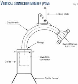
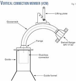
The wellhead structures were designed with three separate receptacles for vertical connection modules (VCMs; Fig. 1). Two separate suppliers of wellheads were used for the project, offering quite dissimilar VCM receptacle designs.
The design length of the flexible jumpers, connecting the rigid flowlines to the subsea wellheads, was 120 m. The production jumpers were thermally insulated to prevent hydrate and wax formation. A VCM structure weighing about 3.5 tonnes was to be connected to the end of each flexible jumper with standard API flanges.
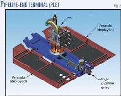
All rigid flowlines were to be terminated at both ends with PLETs (Fig. 2). This was to provide a base for connection of the flexible flowlines to the steel flowlines.
The PLETs at the wellhead end were sealed from seawater by ROV-assisted, removable test caps rated to full test pressure. The test caps had a 2-in. bleed line, sealed by a quarter-turn valve and a check valve to create a double barrier toward the external hydrostatic pressure.
The PLETs at the platform end had built-in, full bore ball valves to stop free flooding, combined with a corrosion cap mounted to the face of the hub. The PLET valve was to permit the riser to be disconnected and replaced with no spillage of the rigid pipe's content.
The overall layout was selected to facilitate pigging and flooding after riser connection and before jumper connection so that the rigid pipelines could be flooded, cleaned, and gauged from the platform. This design, therefore, avoided use of a support vessel and subsea pigging equipment to connect to the PLET.
It should be noted that although the entire system was designed for round-trip pigging with foam pigs, this method could not be used to run the gauging pigs required to prove the integrity of the rigid lines because of the variation in IDs of the production and gas-lift pipelines.
The PLET structures were designed with side-folding verandas to give a total seabed reaction area of 32 sq m necessary to prevent the PLETs from sinking into the low-bearing capacity seabed soils in the area. The verandas were folded in the vertical position during the lowering to the seabed and then deployed (Fig. 2). They were released from their storage position by an ROV that used an hydraulic hot stab to retract locking pins.
The reasons for not wanting to open the verandas on the surface were to avoid added mass problems caused by lowering a structure with such a large area through the water column and to minimize the width of unit to be assembled on the ramp of the Skandi Navica.
Each PLET had a swivel close to the termination flange that tied in to the pipeline end flange. This swivel was designed to avoid rotation of the PLET during installation caused by the possible rotation of the pipeline end from any residual torsion in the reeled and straightened pipe. The PLETs weigh 11 tonnes.
Both gas-lift and production pipelines were API 5L X-60, 0.5% Cr. material. The production flowlines were coated with fusion-bonded epoxy (FBE) and a thermal insulation coating of 60 mm wrapped-solid polypropylene to provide a U-value of 5.3-w/sq m-K.
The gas-lift pipelines were coated with 3 mm of FBE-polyethylene for corrosion and mechanical damage protection. Aluminium bracelet anodes installed every 200 m along the pipe provided further corrosion protection. The PLET structures connected to the pipeline ends with standard API flanges. Table 1 gives pipeline design data.
Electro-hydraulic umbilicals for each of the wells were supplied in sections to facilitate road transportation from the factory to the load-out port of Vitoria. As much as seven sections were required for two of the wells and two sections for the third well. The separate sections needed to be connected offshore on the installation vessel during lay.
The flexible sections at the P-36 platform consisted of lengths of flexible riser, in which the structure was designed for dynamic service connected to lengths of flexible flowline designed for static service. The end fittings had machined API flanges for connection offshore on the installation vessel. The flexible structures for the production flowline had thermal insulation to prevent hydrate and wax formation.
The length of the sections of the dynamic structure was selected to ensure that no part of the static section would lift off the seabed during maximum design excursion of the platform. The static length was designed long enough to ensure no horizontal force would be transmitted to the PLET terminations during maximum design excursion movements for the platform.
The subsea end of the riser was fitted with a VCM for connection to the rigid flowline PLET. Full-bore ball valves were included in the VCMs to enable the risers to be installed empty to reduce top tension during installation.
Pull-in winches, movable sheave blocks, and foundations were pre-installed on the P-36 to facilitate the riser pull-ins. The hang-off facilities fore and aft of the platform allowed the riser to be free hanging from deck level, through the splash zone and down to the seabed. All hang-offs on the side of the platform included short I-tube sections below the surface. The topside layout including the I-tubes was designed for a nominal riser hang-off angle at 4° (vertical).
Installation vessels, activities
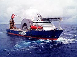
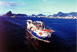
The Skandi Navica is a newly built multi-functional modified platform-supply vessel with diesel electric propulsion (Fig. 3a). The vessel, delivered to DSND in December 1999, is designed to operate mainly as a deepwater pipelay vessel, but it can also carry out offshore installation tasks, laying of flexible pipes, cables, and umbilicals, as well as transport of cargo, pipes, liquid mud, fuel oil, base oil, etc., when not in pipelay mode.
The vessel is equipped with a pipe reel capable of carrying 2,500 tonnes of pipe.
The Fennica, used for pipelay throughout the installation phase of the project, is multi-functional based on a modified icebreaker design with diesel electric propulsion. It is designed to receive deck spreads capable of carrying out such offshore installation tasks as laying of flexible pipes, cables, and umbilicals and providing ROV and survey support.
The 120-tonne (safe working load) A-frame permits deployment of trenching machines and ploughs. Her large bollard pull and winch permit ploughing operations and towing, and she is also equipped for anchor handling.
Main components such as winches, cranes, and A-frame being already installed simplify a change of function.
The Lochnagar is purpose-built and modified according to Petrobras' specification for installation of flexible lines and umbilicals in bundle mode (Fig. 3b). The vessel can perform installation operations down to 2,000 m and can carry 3,000 tonnes of flexible pipes in two carousels in addition to 500 tonnes of umbilicals on two storage reels.
Pre-lay activities
The Fennica mobilized to the project and started working offshore a week ahead of the planned start for rigid-pipeline installation.
Pre-lay survey activities included pipeline route surveys with ROV sonar and video and installing and calibrating of acoustic arrays at the start-up and lay-down locations for the rigid pipelines. The arrays were also used to verify the as-installed positions of the wellhead structures adjust the pipeline-initiation target boxes relative to the as-found positions of the wellheads.
Extensive drilling and well completion were ongoing at the time with three dynamically positioned drilling rigs working in parallel during not only pre-survey but also later during pipeline installation. The drilling rigs had deployed transponder arrays as one of their reference systems and certain "safe" frequencies had been allocated to DSND that had been intended to prevent conflict with the drilling rigs' transponders.
Despite this forward planning, major interference problems were encountered, resulting in the need for the drilling rigs to shut down their transponder interrogation and operate on global positioning (GPS) during calibration and pipelay.
It is outside the scope of this article to investigate the reasons for the interfering frequencies, but it is recommended to avoid this problem by agreement of a "time share" system for the relatively short duration required for calibrating and pipelay activities.
Spoolbase fabrication
A spoolbase for fabrication of rigid 1,000-m pipestalks was constructed in the Samarco base at the Port of Ubu close to Vitoria (Fig. 4). A traditional layout was adopted with one production line for welding, non-destructive testing (NDT), and field-joint coating. The pipestalks were then transferred over to storage racks ready for transfer to the spooling line leading down to the ship.
The layout allowed the first pipestalk welded to be the first pipestalk spooled, which proved to be essential for maintaining the project's installation schedule. The original plan had been to fabricate the pipestalks in the opposite order from the spooling order to allow the main line and fabrication shop also to be used for stalk tie-in welding, NDT, and field-joint coating. This methodology would require all pipestalks to be completed before spooling of the first stalk to the ship.
Mechanized welding robots were used on the main line for the root and hot pass. The NDT acceptance criteria were established from an Engineering Critical Assessment (ECA) conducted in accordance with DnV-2000 rules.1
A high weld-rejection rate was experienced and production rates were dramatically low compared to the planned levels. The main reasons were that the pipe dimensional tolerances were too wide on diameter and wall thickness, although more restricted than API-5L, and that it was very difficult to obtain good quality pipe beveling with locally available equipment and services.
It proved essential to use the results of the ECA to determine a somewhat more generous defect size in order to complete fabrication within an acceptable schedule. It is recommended that more traditional manual pipe welding be used for projects in which optimum quality line pipe, beveling equipment, and services are unavailable.
Rigid-pipeline installation
As mentioned, the rigid pipelines had to be initiated at the wellheads with drilling rigs on location and operating. All rigs kept their stations with dynamic positioning; consequently there were no anchor chains or mooring lines to obstruct pipelay operations.
The pipeline initiation targets, however, were defined by a 20 x 20-m target box with its center 70 m lateral distance from the center of the wellhead structure. The pipelines were initiated with "dead man" anchors with fixed-length initiation wires.
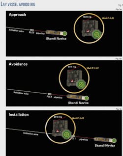
The straight line from the anchor to the center of PLET target box and onto the centerline of the pipelay ran underneath the drilling rig working on the wellhead. Consequently, it was necessary for the Skandi Navica to sidewalk around the drilling rig and simultaneously pay out the pipeline. Once on the far side of the drilling rig, the Skandi Navica had to sidewalk back, pulling the pipeline and initiation wire back under the drill rig (Fig. 5).
These operations progressed with no problems or disagreements with the drilling rig's personnel, and all PLETs were landed within the specified targets.
Buoyancy elements were attached to the PLETs at the surface with ROV-removable rigging. The purpose of these elements was to keep the PLET upright during installation and to keep the bending stress at the flange connection to the flowline within acceptable limits.
The top catenary angle of 80° and the presence of the swivel caused the PLET to be unstable with respect to rotation during the initial phase of the lowering from the installation vessel. This caused the first PLET to turn upside down, and the buoyancy rigging design was such that it would not self-right through 180°.
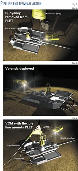
This event had been considered within the contingency procedures where a PLET righting wire was deployed from the support vessel and hooked into wire loops on the PLET structure. The righting procedure was successful and the design of the buoyancy rigging for the remaining PLETs was modified to try to prevent repetition of the problem (Fig. 6a).
The remaining PLETs were then installed upright and without further problems.
Once the PLETs had been successfully landed within their target boxes, sufficient length of pipe was paid out to avoid any movement of the PLET due to vessel excursions. The Fennica ROV was then moved in to cut away the buoyancy modules and release the up-folded PLET verandas.
The PLET verandas had hydraulically operated locking pins designed to lock the verandas in either the vertical deployment position or the horizontal final position. These pins were designed to engage, using springs fitted inside the hydraulic cylinders to ensure a fail-safe pin engagement.
Once the PLET was landed in the target box, a hot stab was inserted to a female receptacle and hydraulic fluid was pumped into the cylinders to retract the locking pins. Once the cylinders were retracted, a quarter-turn valve was closed by the ROV to keep the system pressurized with the locking pins retracted.
The ROV was then able to disengage the hot stab and inspect the PLET to ensure that the verandas were fully deployed (Fig. 6b).
The verandas relied on gravity to fold down from the stored vertical position to the horizontal final installed position. If the verandas would not fold down from gravity, then the ROV would be used to assist in deployment. The tilt of the PLET on the sloping seabed made it necessary to provide ROV assistance in the folding of the veranda on the upside of the PLET.
After both verandas were folded down, the ROV released the hydraulic pressure and performed a visual survey to check that the locking pins had engaged properly.
On several occasions, it was necessary for the Skandi Navica to tension up on the pipeline and lift the PLET slightly off the seabed in order for the verandas to open fully and for the locking pins to be engaged.
Half way through the lay, each pair of rigid flowlines had to cross each other due to the opposite orientation of the connection positions on the platform and the wellheads. The first line was laid with an S configuration half way along, to create the crossing for the second pipeline. The Fennica then installed two 12-m wide crossing structures over the installed pipeline to ensure the required vertical separation between the two pipelines.
The height and separation of the two crossing structures were designed to provide the necessary vertical separation and to ensure that the free span resulting from the crossing was within allowable free-span length for the pipeline.
The second pipeline was also laid with an S configuration onto the crossing structures. The successful construction of all crossings proved that the pipelines could be laid with high lateral positional accuracy in water depths close to 2,000 m .
At the P-36 end, the pipelines were terminated with PLETs of similar design to that used for the initiation end and with similar installation procedures as for the wellhead end.
Installing the first PLET at the P-36 end experienced lateral instability of the PLET from the extreme seabed slope at the location. After the lay-down wire was removed from the PLET, it slid sideways down the slope for more than 100 m before it could be stopped by the attachment of a work wire from the Fennica being hooked onto the PLET by ROV.
The Skandi Navica then had to hook its abandonment and recovery wire onto the PLET and sidewalk the PLET and pipeline back into position. The Fennica then removed the buoyancy and released the verandas, whereupon the PLET appeared to settle in a stable condition.
A clump weight anchor with a penetration skirt was installed on the up side of the PLET and hooked to the PLET by the ROV-connected rigging to provide further security. Skirt penetration plates were welded to the verandas of the remaining lay-down PLETs and no more instability was experienced.
Installation of flexibles, umbilicals
The flexible flowlines and risers, umbilicals, and flexible jumpers were installed by the PLSV Lochnagar.
For this project, the vessel was released from its day-rate contract and performed as part of a lump-sum contract. The project required no major changes to the work methods that were then employed by the vessel because the installation tasks were considered standard operations with the exception of the need to operate down to a record-breaking water depth of 1,870 m.
The flexible risers were initiated with a VCM for connection to the rigid pipeline's PLET (Fig. 6c). The non-insulated 4-in. gas lift risers were launched and connected in water depth down to 1,526 m with no special problems. Major problems were experienced, however, by torque in the 6-in. insulated risers, which resulted in the orientation of the VCMs at the seabed being out with the tolerance required to land and connect the VCM to the PLET hubs.
The first riser was examined by the ROV to determine the magnitude and direction of twist in the line. The riser was then recovered to the surface and the VCM re-orientated according to the observed twist caused by the torsion in the riser.
The torsional effect proved to be repetitive, and on the second attempt the riser was landed and connected successfully to the PLET. The following procedure was then adopted for the remaining risers:
A clump weight was attached to a blind flange start-up head and the riser was launched down to a depth where the ROV went in and observed the magnitude of rotation in the riser.
The riser was then recovered, and the VCM was fitted in an orientation to compensate for the observed amount of twist. The 6-in. insulated flexible jumpers at the wellheads, which were only 120 m long, exhibited the same characteristic, causing major delays due to recovery and VCM adjustment.
The cause of the twisting has not been fully identified but can most likely resulted from torsion induced by trans-spooling on and off reels and into the lay vessel's storage baskets. The problem should be investigated because it resulted in major delay and handling uncertainties during installation.
For the first umbilical installed, problems were experienced with the electrical connectors joining the umbilical sections. After launching and exposure to the hydrostatic pressure at the seabed, the insulation resistance measurements showed low values that indicated seawater flooding of the connectors. This required the umbilical to be recovered and several of the electrical connectors had to be replaced offshore.
All replaced connectors performed to specification, and it was concluded that the problems were not caused by the high hydrostatic pressure. This conclusion was further substantiated after successful installation of the umbilicals for the two other wells, which were supplied by another umbilical manufacturer, using identical electrical connectors.
Pre-commissioning
Upon connection of the risers to the rigid flowlines and before connection of the flexible jumpers, the risers and rigid pipelines were cleaned, gauge pigged, and filled with filtered seawater.
During this operation, the pipelines were vented through bleed valves in the test caps on the wellhead side of the PLETs. The pigs were run through the pipelines and up against the test caps when the pumping operations were stopped. The jumper installation vessel then removed the test caps, fitted pig catchers onto the PLET hubs, and the pigs were expelled into the catchers by pumping from the P-36 platform.
Upon acceptance of the gauge plates, the jumpers were connected between the pipelines and the wellheads, forming a closed loop. The entire pipeline was then filled with treated and inhibited water by pumping of a foam pig down the 4-in. pipeline, through the christmas tree, and back up the 6-in. pipeline to the platform.
Hydrotesting of the entire system was performed from the P-36 platform, and the lines were then depressurized and handed over to Petrobras.
Acknowledgment
The authors thank Petrobras for the opportunity to publish this article.
Reference
- Det Norske Veritas, "Offshore Standard OS-F101, Submarine Pipeline Systems," January 2000.
The authors
Marcos Guedes Gomes Morais is manager of the offshore installation group, engineering department. Before that he was manager of the subsea deepwater technology group. He holds a degree (1979) in mechanical engineering from the Universidade Federal Fluminense, Niterói, Brazil, and an MBA (1999) in Technology Management, from Fundação Getúlio Vargas.
Fabio Braga de Azevedo works in the design group of Petrobras with activities mainly in the area of pipelines. From 1999 to 2000, he was project engineer for design and installation of the flowlines in Roncador field. Azevedo holds a degree (1975) in mechanical engineering from the Universidade Federal Fluminense, Niterói, Brazil, and an MSc (1998) in subsea engineering from Heriot-Watt University, UK.
Odd Kvello joined DSND Subsea AS in February 2000 as pipeline engineering manger. Previously, Coflexip Stena Offshore Norge em ployed him as senior engineer from July 1995 and employed him as rigid pipelines design supervisor from August 1996. Kvello holds a master of science in mechanical engineering (1988) from the Norwegian Institute of Technology.
Peter Tanscheit is a senior project engineer for DSND Consub SA, which he joined in March 1992. He holds an undergraduate degree (1989) and an MSc (1991), both in mechanical engineering, from Pontifícia Universidade Católica, Rio de Janeiro.
Based on a presentation to the Offshore Technology Conference, Houston, Apr. 30-May 3, 2001.
