Testing, analysis solve insulation problem on gulf flowline
Upon start-up in late 1997, the Troika flowline system, offshore Louisiana Gulf of Mexico, evinced poor thermal insulating properties when the arrival temperature of produced fluids at the host platform was about 50° F. lower than expected.
An investigation in 1998 included analysis, field measurements, and land tests of an 80-ft section of the Troika flowline bundle evaluated the cause of the properties and led to a remediation plan.
The field data and test program identified the cause of the poor thermal performance to be convection of the pressurized nitrogen in or around the flowline's insulating foam.
The test program demonstrated that damage to the foam directly affected the resulting thermal performance (U-value).
The program also revealed that burial of one flowline improves the thermal properties of the system sufficiently to operate the system outside the hydrate-formation region.
The cool-down times for a buried flowline far exceeded the original cool-down criteria of 24 hr once steady-state conditions are obtained. Low-dosage hydrate inhibitors (LDHIs) were also indicated as required for cold-start conditions.
The program further revealed that open-cell-foam application methods (such as foamed in place) that adhere to the pipe need to be evaluated as methods to minimize foam damage resulting in gaps that enhance convection. Alternative systems that minimize the convection mechanism should also be investigated as a means to insulate pressurized bundles.
The use of syntactic foam or other materials that can withstand the annulus pressure without letting the nitrogen permeate are alternatives that should also be considered. These materials have higher thermal conductivity, however, and are likely to be much higher in cost because of greater material cost and the impact of their greater weight on required casing diameter.
The investigation and remediation plan are the subjects of this article.
The flowline
Troika, a deepwater (2,700 ft) oil development in the Gulf of Mexico, lies about 150 miles south of New Orleans. The reserves are being recovered through an eight-slot manifold cluster subsea production system in Green Canyon (GC) 200 tied back to the Bullwinkle platform in 1,350 ft of water in GC 65.
Commingled flow from five initial wells flows to Bullwinkle through two 14 mile, 10.75-in. OD pipe-in-pipe insulated flowlines. Well control is maintained with an electrohydraulic control system through separate electrical and hydraulic-chemical umbilicals.
The two 14-mile flowlines were installed by bottom tow in four, 7-mile segments. Each segment was fabricated at a beach makeup site, laterally launched, bottom towed 400 miles through a maximum water depth of 3,200 ft, positioned in the field, and connected.
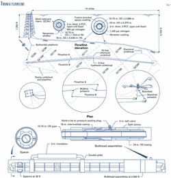
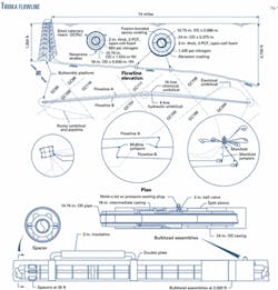
Connection to the Bullwinkle platform entailed lifting the riser end to the surface and securing it to the jacket leg in a catenary configuration. Insulated steel pipe jumpers were used to join the 7-mile sections at the midline and subsea manifold locations. Fig. 1 shows an overview of the Troika flowline system. Further details on the Troika system can be found elsewhere.1 2
The upper part of Fig. 1shows the field layout; the lower part shows the various components along the flowline bundle.
The steel catenary risers (SCRs) at Bullwinkle are a pipe-in-pipe configuration with a 10.75-in. x 1.024-in. production line inside an 18-in. x 0.5-in. outer casing pipe.
The 10.75-in. production line is surrounded by a 2-in. thick layer of 2-pcf open cell polyurethane foam. The foam consists of 6-ft long half shells that are secured to the 10.75-in. production pipe with tape and plastic straps.
Polyurethane spacers are installed every 35-ft to support 10.75-in. pipe relative to the 18-in. casing. The annular area of the SCR is pressurized with 650-psig nitrogen at 40° F. to prevent collapse of the 18-in. casing when towed through the deepest water depths along the bottom-tow route.
A bulkhead separates the SCR section from the flowline section. The nitrogen pressure in the SCR sections was removed after startup in an attempt to improve thermal performance but without noticeable change.
The flowline bundle segments from the SCRs to the subsea manifold are a pipe-in-pipe configuration with 10.75-in. x 0.866-in. production pipe inside a 24-in. x 0.375-in. casing pipe. The 10.75-in. production line is surrounded by a 3-in. thick layer of 2-pcf open cell polyurethane foam consisting of 6-ft long half shells secured to the 10.75-in. production pipe with tape and plastic straps. Polyurethane spacers installed every 35-ft support the 10.75-in. pipe relative to the 24-in. casing (Fig. 1).
The annular area of the flowline bundle is pressurized with nitrogen to 1,435 psig at 40° F.
The 24-in. casing pipe's wall thickness and nitrogen pressure were designed to prevent collapse and provide a low on-bottom submerged weight for the tow method of installation.
This is accomplished by trading-off wall thickness of the 24-in. casing against nitrogen pressure until the required submerged weight is achieved. At 1,435 psig, the nitrogen is a significant part of the on-bottom bundle weight and is needed for on-bottom stability when there is no liquid in the flowline.
The nitrogen pressure in the 24-in. flowline bundle could be reduced by addition of external weight, but a significant portion must remain to prevent collapse of the casing from external hydrostatic pressure.
Bulkhead assemblies (lower part of Fig. 1) are installed along the flowline bundle at 2,000-ft intervals to limit flooding if the casing is breached. The bulkhead assemblies were designed to minimize heat loss at these locations by including an intermediate 18-in. casing pipe (Fig. 1).
One of the 2,000-ft compartments nearest the SCR was inadvertently flooded during installation with no discernible difference in thermal performance between the two flowlines.
The flowline profile (upper part of Fig. 1) shows a hump just downstream of the midline jumpers. This is where favorable hydrate conditions first occur during a cool down, discussed presently.
Performance criteria
Thermal performance criteria for the Troika flowlines derive from the need to prevent hydrate blockage. Hydrates are solids formed when gas and water combine at low temperature or high pressure. A temperature high enough or pressure low enough prevents hydrates from forming and hydrate blockage from occurring.
Under steady-state flow, heat is continually added to the system by the production stream and lost to the environment through the flowlines and other parts of the production system. When a shut-in occurs, the produced fluids begin to cool.
Cool-down time is how long it takes the flowline contents to cool to the hydrate-dissociation temperature at the pressure of the contents.
The original operating strategy of Troika relied on methanol, residual heat in the flowline system, and depressurization of the flowlines to prevent the formation of hydrates. From a cold start, methanol is injected during a warm-up period.
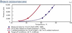
When the flow stream arriving at Bullwinkle is safely above the hydrate-dissociation temperature (Fig. 2) at flowing pressure, methanol injection is discontinued. When a shut-in occurs, no action is taken until the temperature threatens to drop below the hydrate-dissociation temperature. If necessary the flowline is depressurized to prevent hydrate formation.
The Troika flowline insulation system was designed to allow 24 hr of cool-down time before reaching hydrate-formation conditions. This established the required flowline system overall heat-transfer coefficient (U-value) of 0.176 btu/hr-sq ft-°F. referenced to the ID of the 10.75-in. pipe (UR), including the effect of the bulkheads and spacers.
The resulting U-value was theoretically expected to provide arrival temperatures at Bullwinkle ranging from 95° F. to 145° F., depending on flow rate.
These values along with the anticipated heat retention of the flowlines would have been sufficient to prevent paraffin deposition or formation of hydrates during production and provide a cool-down time greater than 24 hr as soon as the arrival temperature reached 75° F.
In addition to the flowline, all components of the production path were insulated including trees, well jumpers, manifold piping, flowline jumpers, and flowline end terminations to prevent localized heat losses.
As stated earlier, the thermal performance of the Troika system did not meet design expectations. Arrival temperatures were approximately 50° F. cooler than anticipated, and the time between shut-in and hydrate formation temperature is about 6 hr at initial operating conditions.
Evaluation of field data indicates a steady-state overall heat-transfer coefficient (UR, based the ID of the 10.75 -in. pipe) in the range of 1.8 to 2.5 btu/hr-sq ft-°F., increasing with increasing production rates. This dependence on production rate indicates a convective heat-transfer mechanism.
Experimental work has confirmed the convective nature of heat transfer in the bundle and quantified the relationship between effective conductivity of the open-cell polyurethane foam and nitrogen pressure (discussed presently).
Remediation options
The investigation to establish the thermal remediation requirements reviewed the production forecast and operating needs. The production forecast shows significant produced water beginning in late 2000 to early 2001. At the onset of produced water, all of the wet wells could be produced down one flowline with the remaining dry wells produced down the second flowline.
Later in the field life when all wells are wet, the production will fall off so that all production can be produced down one flowline. This indicates that modification of one flowline will be sufficient for the Troika well stream to be produced outside the hydrate-formation region.
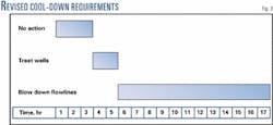
A review of the cool-down time based on operating experience led to the conclusion that the required cool-down time could be reduced to about 17 hr (Fig. 3). This can be reduced by an additional 2 hr by simultaneous treatment of the wells and depressurization of the flowlines when necessary.
The range of options for improving the thermal performance of the flowlines includes: use of chemical inhibitors, covering the exterior of the flowline casing with additional insulation, or altering the contents of the annulus.
This led to investigation of the following thermal remedial methods: use of hydrate inhibitors, burial, insulating shrouds, reducing the nitrogen pressure in the annulus, and replacing the nitrogen with a material designed to reduce or eliminate convective heat transfer.
Burial
The burial option improves flowline thermal performance by lowering the overall system U-value and adding thermal mass to the system (increases heat retention). Small-scale tests showed that the effectiveness of burial depends on the soil backfill.
It is important to obtain a consistent soil backfill that completely covers the pipeline. Testing of chunky soil conditions that could result from a backfill plow demonstrated convection through a loose backfill. Convection of the soil was not evident for a jetted backfill even with the low shear strength soils along the Troika flowline route.
Industry in 1999 was developing equipment for burial of a deepwater pipeline. This same equipment can be modified for burial of deepwater large-diameter pipelines such as the Troika flowlines.
Burial proved to be the most cost effective of the options considered and is recommended for remediating one of the Troika flowlines.
For the burial method to be applicable for the Troika flowlines, it will be necessary to add weight to the bundle to obtain the specific gravity needed to prevent the bundle's resurfacing after burial.
The additional weight can be in the form of external weight or by flooding the flowline bundle annulus with water. The recommended approach is to flood the annulus with inhibited seawater.
Inhibitors
The methanol-delivery system cannot deliver enough for the expected water cuts later in the field life with the existing thermal properties of the flowline. In addition, the thermal mass for a buried system takes longer to warm up from a cold start requiring higher volumes of methanol than the system can currently deliver. Alternative hydrate inhibitors were therefore evaluated.
Low-dosage hydrate inhibitors (LDHIs) are an emerging technology in offshore oil and gas production. They are low-dose chemicals (0.1-3 wt % of water phase) that can afford protection against hydrate blockage of the flowlines without the large volumes and expense associated with methanol or monoethylene glycol (MEG).
LDHIs include kinetic inhibitors and dispersants. Kinetic inhibitors work by preventing onset of hydrate formation, extending the induction time to form hydrate crystals. Kinetic inhibitors do not change the conditions at which formation begins.
With adequate dosage, however, kinetic inhibitors can give up to 48 hr of protection before hydrates form. These inhibitors greatly depend on cool-down rate. The higher the rate, the less likely a hydrate plug will form.
Dispersants work by forming an oil-water emulsion that disperses the hydrate particles when hydrates begin to form. The dispersants do not affect the conditions at which hydrate formation begins but keep the hydrates in a slurry so they cannot plug the flowline.
Use of LDHIs continuously with the current system proved technically feasible but extremely expensive. LDHIs are viable and recommended with the burial option for cold-start conditions.
Shrouds
The thermal remediation investigation evaluated concrete or foam composite shrouds set onto the 24-in. flowline casing in an inverted U-configuration. The shrouds consist of a concrete outer shell with a foam layer in the mid-section.
The shrouds were found to be the highest cost when used over the entire 14-mile flowline length. They are potentially useful for shorter sections of the flowline where burial is impractical but did not perform as predicted.
Observations during the test program suggest the effective thermal performance of the shroud is reduced by exchange of water between the shroud and the bundle with the ambient cold-water environment. The exchange is thought to take place through the gaps between the shrouds.
If continued development of shrouds is warranted, specific provisions need to be included to prevent the free flow of water between the environment and the annular space defined by the bundle, shroud, and soil. These provisions should also address the interstitial space between the shroud and the mud line.
A preferred approach would be to fill this space with mud from the bottom or with another material such as grout. The sensitivity of the shrouds to hydrostatic pressure should also be evaluated to investigate general collapse and weight gain after an extended period of immersion in a hyperbaric environment.
Nitrogen pressure reduction
Testing has shown that reducing the nitrogen pressure in the flowline bundle annulus can improve the system thermal performance. The bundle design, however, will not support sufficient reduction in nitrogen pressure needed to restore adequate thermal performance.
Nitrogen pressure is required to prevent collapse of the casing due to external hydrostatic pressure. In addition, the nitrogen provides weight to the bundle, and depressurization would require adding weight to offset the lost nitrogen.
Based on these considerations, the bundle was analyzed for reducing the nitrogen pressure in the deep 7-mile segment to 1,000 psig and the shallower 7-mile segment to 750 psig. The results appear in a subsequent section.
Insulating materials
Several internal insulating materials were evaluated including water-based in situ polymers, organic oils (synthetic oils), foamed cement, cement or seawater with microspheres, high-viscosity oils, oil-base gels, water-base gels, and epoxy foam.
Whatever material was selected had to be environmentally benign. The oil-base materials provided great improvement to the thermal properties of the flowline but were eliminated due to environmental concerns.
To be effective, the insulating material must have a low viscosity for injection into the annulus and a high viscosity (gelled) after the material is in place. The gelled material also needs to remain stable at temperatures of 160°F. over the field life. An acrylate monomer was found to be best suited at the time of this evaluation.
The acrylate monomer is dissolved into seawater at about 8% and polymerizes in situ. Gelling can be prevented for up to about 20 hr, after which solidification begins.
The internal insulating materials were eliminated in favor of burial because of estimated cost and installation risk. High costs are associated with the hot taps, material costs, and offshore time required to inject the insulating material at a controlled rate.
The installation risk is associated with hot tapping the casing, displacing the nitrogen, injecting the gel through the bulkhead piping (Fig. 1), and the potential for the material to gel before completion.
Testing results
The test program investigated the thermal performance of the flowline system as installed and the remedial options to restore the flowline thermal properties to an acceptable level.
An 80-ft long section of the Troika flowline bundle was constructed and placed in a large tank of water. The tank was chilled and maintained at constant temperature for each test. Heat was applied to the bundle by electric heaters internal to the flowline. Power consumption was monitored to determine the steady-state heat loss from the bundle for a variety of conditions.
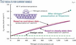
The test section was fitted with thermocouples on the flowline, insulation, and casing to determine the temperature drops throughout the bundle. This instrumentation allowed determination of the overall U-value during a cool down. Fig. 4 presents a comparison of data obtained from steady state and cool-down tests and shows good agreement between the two methods for determining the system U-value.
Bundle performance
Fig. 4 presents the test results for the bundle test section set on a sand bottom to establish a baseline for comparison to field data.
The diagram demonstrates the effect of nitrogen pressure on thermal performance. At atmospheric pressure, the bundle system behaved consistently with design specifications (UR of about 0.176 btu/hr-sq ft-°F.). The bundle's thermal performance degraded as the nitrogen pressure increased to 1,500 psig (UR of about 1.25 btu/hr-sq ft-°F.). This U-value is lower than indicated by the field data (1.8 to 2.5 btu/hr-sq ft-°F.).
A U-value within the range of the field data (2 btu/hr-sq ft-°F.) was achieved by pressurization of the bundle at a rate of 10 psig/min (Fig. 4). Degradation of bundle's thermal performance results from convection in or around the foam.
Pressure tests on the foam revealed that cracks and shrinkage had occurred. The shrinkage caused the foam insulation to fit loosely and a crescent-shaped gap to form between the 10.75-in. pipe and foam over the lower half of the cross-section.
The shrinkage also caused the longitudinal seams of the half shells partially to separate from each other, opening up channels. Longitudinal cracks were also observed in the foam half shells. The extent of damage appears to be related to the pressurization rate. More damage occurs at higher pressurization rates.
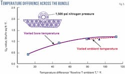
Fig. 5 depicts the variation in U-value for a range of temperature differences across the bundle cross-section. Varying the internal bore temperature relative to the ambient water temperature or varying the ambient water temperature relative to the bore temperature yields the same results (Fig. 5).
Fig. 5 shows the dependence of U-value on temperature difference.
In a purely conductive system, U-value is a constant for all temperatures. In a convective system, the U-value depends on the temperature difference in the convecting fluid. This means that U-value variations driven by changes in temperature indicate that convection is a significant mechanism of heat transfer in the installed bundle.
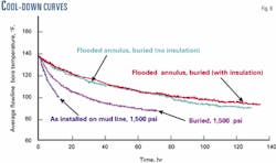
Fig. 6 depicts the cool-down curve for the flowline bundle pressurized with 1,500-psig nitrogen. The contents of the flowline in this case include water and the heating element. Fig. 6 also shows a curve that has been calculated for a gas-filled pipeline to represent the cool down in the field.
Flowline burial
For a burial depth of 33 in. (21-in. cover), test results indicate that the overall heat transfer coefficient will be between 1.1 and 1.4 btu/hr-sq ft-°F.
The lower value was measured with insulation and the bundle annulus filled with water. The higher value was measured after the insulation had been removed from the bundle and the casing filled with water.
To prepare the sample, the casing was first pressurized to 1,200 psig with nitrogen and then water was pumped into the casing until the water displaced all of the free nitrogen. This process was carefully controlled to simulate the controlled flooding of a bundle on the seafloor.
The test immediately before burial of the flowline measured the thermal performance of the bundle in open water following rapid pressurization. In this condition, the test section had a U-value of 1.96 btu/hr-sq ft-°F. Burying the bundle 33 in. (21-in. cover) in bentonite mud improved thermal performance of the test section to 1.04 btu/hr-sq ft-°F.
Fig. 6 shows the influence of burial on cool-down performance for a water-filled flowline. The plot demonstrates that burial increases cool-down times relative to the unburied condition and that flooding the annulus favorably influences cool-down performance.
The thermal performance of the buried test section is considerably less than predicted by the classic heat-transfer formula for a buried pipeline or else the thermal conductivity of the soil is not as predicted.
The bentonite mud had a density of 9.2 ppg. The thermal conductivity is estimated to be 0.42 btu/hr-sq ft-°F. Explanations for the inconsistency include the size of the tank and flow of water through cracks in the soil.
There was no evidence of convection of the soil itself; significant cracks had developed in the soil, however, as a result of generalized shrinkage of the soil mass as water continued to be absorbed by the bentonite. Convection of free water through these cracks may have contributed to thermal losses during the test.
In addition, the characteristics of the tank influenced cool down of the system. The width (10 ft) of the tank provided approximately two pipe diameters from the edge of the pipe to the cooling pipes lining the sides of the tank. On this basis, it is likely that the tests over-predict the heat loss relative to a uniform backfill.
Analysis results
Numerical analysis to evaluate the thermal performance of the flowline used the test and field data to evaluate system behavior. After the flowline system model was constructed, cool-down computations were run by simulation of shutdowns for an array of initial steady-state starting flow rates.
Cool-down times were then calculated by interrogating simulation results for first occurrence of hydrate conditions anywhere in the flowline. Onset of hydrate formation was determined to be any pressure and temperature pair that exceeded the hydrate-dissociation curve (Fig. 2).
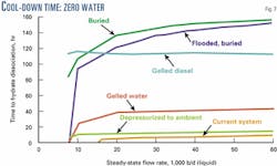
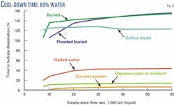
Figs. 7 and 8 depict results of the analysis for 0% and 60% water cuts. The diagrams also depict the time to the hydrate-dissociation temperature plotted against the steady-state flowrate. The lower curve is for the existing system and shows a cool-down time of about 6 hr for flow rates greater than 15,000 b/d.
Both burial cases (with current system and annulus filled with seawater) and gelled diesel are clearly the better thermal remediation options. Gelled diesel was not considered because of environmental concerns, and gelled water was eliminated because of installation risks.
In all cases, the hump just down stream of the midline jumpers (Fig. 1) is where hydrate conditions first appeared. Hydrate conditions at the manifold, where hydrates are more likely to occur (because of water build up) appear later, making the times presented in Figs. 7 and 8 conservative.
The 0% water-cut case is the most severe case. As water production builds, additional thermal mass will have a slight tendency to extend the cool-down time. Distortion of the curves in Fig. 8 relative to Fig. 7 is largely due to the distribution of vapor and liquid phases after the line has been shut down.
Most notable is the shift of the buried flowline with flooded annulus to higher cool-down times than the non-flooded case. This results from the combination of higher bulk thermal mass as well as lower void fraction and therefore lower vapor surface area exposed in the interior on the flowline.
The long cool-down times for burial will require long warm-up periods in a cold-start condition. In such a condition, the injection of low-dosage hydrate inhibitors will be required until the system has reached a safe steady-state temperature.
Acknowledgments
We thank BP PLC, Marathon Oil Co., and Shell Oil Co. for permission to publish this article.
References
- Beckmann, M. M. et al. "Troika- Towed Bundle Flowlines," Offshore Technology Conference, May 4-7, 1998, Houston.
- Bednar, J. M. "Troika Subsea Production System: An Overview," Offshore Technology Conference, May 4-7, 1998, Houston.
The authors
Marvin Beckmann is president of Manatee Inc., Houston. He has more than 20 years' experience in the offshore oil and gas industry including such deepwater subsea developments as Zinc, Pompano II, and Troika. He holds a BS (1976) from the University of Texas and an MS (1980) from Rice University. He is a member of the American Society of Civil Engineers.
Bruce Volkert is an employee of Manatee Inc., Houston, and has more than 23 years' experience in the offshore oil and gas industry. He has worked on several deepwater subsea developments including Cobia 2 Post Mortem, North Fluorite, Zinc, Troika, and Europa. Volkert holds bachelors (1976) and masters (1978) of science degrees from the University of Illinois. He is a member of the ASME and SPE.
Norm McMullen is consulting facilities engineer for flow assurance in deepwater technology for BP PLC, for which he has been employed since 1997. Before joining BP, he was president of PipeSoft Corp. for 4 years and held many positions in Chevron Corp. for the previous 20 years. McMullen holds a BS (1973) and MS (1974) from the University of Washington, both in mechanical engineering. He is a member of SPE.
Based on a presentation to the Offshore Technology Conference, Houston, Apr. 30 - May 3, 2001.
