Calculations help determine carbon steel piping in cold temperature relief service


Gas processing facilities may have flare or vent systems that occasionally handle cold relief flows for short periods of time. Although nonimpact-tested carbon steel piping is not typically used for cold service applications, its use in the main flare headers of facilities with intermittent occasional cold relief flows was evaluated.
Stress analysis of the flare header can be used to determine if nonimpact-tested carbon steel is a suitable material of construction. This article discusses the calculations required to evaluate the use of nonimpact-tested carbon steel piping in cold intermittent services per the ANSI B31.3 guidelines, prior to the 2000 B31.3 addendum. The 2000 addendum includes additional calculations (not discussed in detail in this article) that are less restrictive in the application of nonimpact-tested carbon steel for intermittent cold services.
This article also discusses simple steady state and nonsteady state heat transfer calculations that can be used to estimate the impact of intermittent cold relief flows on flare header piping. These calculations can be part of a risk analysis process to assess the suitability of nonimpact-tested carbon steel for a given application.
Design conditions
During a hazard analysis review mandated to meet process safety management (PSM) requirements, the authors checked to see if the design pressures and temperatures of equipment and piping were adequate for the conditions to which they could be exposed. Vent and flare header systems were part of this evaluation.
Different locations were found to have different materials of construction. Some systems were constructed entirely of nonimpact-tested carbon steel (typically referred to as mild carbon steel such as types ASTM A53 Grade B, ASTM A106 Grade B, ASTM A234 Grade WPB for formed fittings and ASTM A105 for forged fittings). Other systems were constructed of impact-tested carbon steel (typically referred to as low-temperature carbon steel such as ASTM A333 Grades 1 or 6, ASTM A420 Grade WPL6 or WPL6WX for formed fittings, and ASTM A350 Grade LF2 for forged fittings).
Still others were constructed of a mixture of nonimpact-tested carbon steel, impact-tested carbon steel, and types 304 or 316 stainless steel. For example at one location, some of the relief valves and outlet piping to the main header were stainless steel, but the main header was nonimpact-tested carbon steel except for the elbows which were impact-tested carbon steel.
Some differences were obviously due to different design conditions. The age of the plant, however, and whether the plant was designed and built by the operator-user company or another company had an impact on the materials of construction.
Material toughness requirements were based on materials of construction, wall thickness, and design temperatures. Charpy V notch impact tests were typically used for toughness testing.
Temperature specifications for piping
Typical project piping standards state that nonimpact-tested carbon steel can be specified as the material of construction for piping with a minimum design temperature of -20° F. (-29° C.).
Impact-tested carbon steel can be specified with minimum design temperatures down to -50° F. (-46° C.). Types 304 or 316 stainless steel can be specified for design temperatures below -50° F. Project piping standards are generally based on the industry piping standard ASME B31.3.1
Additional review
In a typical gas processing facility, temperatures below -20° F. are common. Even warmer streams such as natural gas liquids (NGL) products or the higher-pressure gas streams have the potential to go below -20° F. during pressure letdown due to Joule Thomson cooling. Relief or vent systems often have the potential for handling streams with temperatures lower than -20° F.
Additional review and study were done on the relief and vent streams where process simulations showed that there was a potential to have temperatures lower than -20° F. Operating nonimpact-tested carbon steel piping at temperatures below -20° F. could lead to a cold brittle fracture failure of the piping.
Obviously, it is an important area to design correctly. However, replacing the piping in an existing vent or flare header system typically would involve significant costs and downtime. It is not something that we wish to do unless it is absolutely necessary.
Further study
The first criterion for further study was that the calculated temperature of the fluid going into the relief or vent header be less than -20° F. Process simulations were used to calculate the expected temperature.
We used the HYSIS or HYSIM process simulation programs for most of the calculations. Some situations, such as the relief valve flow from a fire around an ethane-propane-butane natural gasoline mixture (EPBC) storage vessel, did not have cold temperatures even though most instances of throttling this fluid would cause cold temperatures. This is because the conditions that cause the relief valve to open also cause higher venting temperatures.
Guidelines for determining the situations to consider in relief valve discharges were based on API RP 521.2 All process temperatures below -20° F. were flagged for further evaluation.
The second criterion for further study was that the system have components of nonimpact-tested carbon steel. In some instances, the type of steel used in the nonimpact-tested piping was similar to the type of steel used in the impact-tested piping.
We briefly checked to see if in this instance we could upgrade rating of the steel through testing to meet the impact-test requirements. We found that it was perhaps technically possible, but not practical nor feasible, for our applications.
To do an impact test requires a destructive test of the components in question.3 To do this for existing piping would have required cutting out a section from each pipe and fitting. If the testing and documentation of the material are not done during construction, it is very difficult, if not impossible, to recreate this documentation several years later.
B31.3 criteria
Although the minimum design temperature for nonimpact-tested carbon steel piping with a wall thickness less than 0.5 in. is -20° F., B31.3 allows for "occasional variations of pressure and/or temperature which shall be considered in selecting design pressure and design temperature."
Intermittent temperatures as low as -50° F. (-46° C.) are allowable if certain conditions are met.4 At the time that these conditions were reviewed, the criteria in B31.3 for occasional variations of temperature below -20° F. (-29° C.) with nonimpact-tested carbon steel included the following:
- The design temperature is at or above -50° F. (-46° C.).
- The maximum operating pressure of the manufactured components will not exceed 25% of the maximum allowable design pressure at ambient temperature.
- Longitudinal stress due to pressure, dead weight, and displacement strain does not exceed 6 ksi (41 Mpa).5
An addendum to B31.3 issued in 2000 modified the requirements under which intermittent cold flows are allowable in nonimpact tested carbon steel.6 The requirements now are more liberalized and are similar to the fracture mechanics guidelines found in the pressure vessel code ASME Section VIII.6
Piping analysis per criteria
When we reviewed various flare and vent header systems with nonimpact-tested carbon steel piping, we found that some of the main headers met the criteria to allow the piping to handle occasional flows down to -50° F.
The pressure profiles of the headers were calculated with process simulation programs. In most cases, the calculated pressure in the headers was less than 25% of the design pressure.
One reason that the design pressure of the main headers usually met the 25% of maximum allowable design pressure criteria was that the flow conditions that established the size of the main headers were typically not the same conditions that had the colder temperatures.
Hoop and longitudinal-stress calculations were done using the Caesar program, and the piping isometrics and pipe support details were field-verified before being entered into it. The calculation of the piping stress included the stress forces due to temperature changes.
For a conservative basis for the calculations, we assumed that the piping temperature for thermal contraction was the coldest possible fluid temperature in the piping.
The hoop stress under the cold piping conditions was verified to be less than 25% of the allowable yield stress at ambient temperature for the piping material. In checking the longitudinal stress, the pressure, dead weight, and displacement stress were considered together to be less than 6 ksi.
Possible remediation
In one location with excessive stress due to the thermal contraction of the piping, the installation of an expansion joint could be used to reduce the stress to an acceptable level.
The capital and installation costs for installing an expansion joint were reasonable (less than $25,000). The main drawbacks of this option were the down time, purging, and isolation required to do the installation work.
Heat transfer, temperature calculations
Several brief heat transfer and temperature calculations were done on the cold flows in nonimpact-tested carbon steel pipe to determine if the heat transfer of the system would be such that sections of the piping would not experience temperatures below -20° F.
The calculations showed that under certain conditions sections of the relief system did not experience temperatures below -20° F.
However, because the piping would not be above -20° F. under all the possible conditions, these calculations alone in most instances would not justify the use of nonimpact-tested carbon steel for the relief systems. They did show that not every cold relief exposed all the system piping to temperatures below -20° F. The calculations were based on bare piping and did not include the impact of ice build-up on piping.
Liquid thermal relief
One of the most obvious examples of this is a relief discharge that occurs due to thermal expansion of blocked-in fluids. Typically in gas processing applications, the thermal expansion involves NGL streams with normal temperatures cooler than ambient that are blocked in and experience overpressure due to the thermal expansion from ambient warming.
Often the relief situations due to the thermal expansion of NGL liquids have calculated relieving temperatures below -20° F. but involve a very small amount of relieved fluid and overall cold energy.
The total amount of fluid relieved from a blocked-in liquid expansion can be calculated from the initial fluid volume, the fluid temperature change, and the density of the fluid at different conditions. The formula for calculating the mass of the relieved fluid is relatively simple (Equation 1).
The energy change to warm the relieved fluid up to -20° F. can be compared with the energy required to cool the ambient temperature piping to below -20° F. Process simulation programs are used to calculate the energy change of the relieved fluid.
The piping energy change can be calculated with Equation 2.
Often there is not enough cold energy in the relieved fluid to cool the piping to below -20° F. For a more rigorous analysis of thermal expansion, the calculations can be done stepwise with the volume change from the relieving point to the reset pressure of the relief valve using piping heat loss or heat gain calculations for the blocked in piping and relief header piping.
The most conservative ambient condition to use for the step-wise calculation is the maximum ambient temperature.
Steady state heat transfer calculations
There was a question of enough heat transfer through the bare relief piping to increase significantly the temperature of relieved fluid for situations other than thermal relief flows.
For situations with a significant relief flow, such as loss of reflux to a de-ethanizer or a tube rupture in a chiller, there was no significant temperature change at steady state conditions.
In fact, in some calculations using a process simulation program, the cooling due to the Joule-Thomson effect of the header pressure drop was greater than the warming from ambient conditions through the bare relief header piping.
For the piping-stress analysis, it was assumed that the temperature of the piping was equal to the temperature of the fluid flowing in it. It was recognized that this was a conservative assumption. For insulated piping that has a continuous, nearly constant flow, this is probably not a bad assumption. However, it is reasonable to question if this is really a valid assumption for an uninsulated flare or vent header with an intermittent and usually short-duration flow.
The temperature of the piping at steady state conditions is a function of the temperature of the fluid in the piping, the outside ambient temperature, the inside heat transfer coefficient (film coefficient), and the outside heat transfer coefficient. Equation 3 calculates the wall temperature of the piping.
If the inside and outside coefficients are equal, then the steady state pipe wall temperature is midway between the inside and outside temperatures. The heat transfer coefficients depend on several variables, but for a given system, velocity is the variable that causes the most deviation in the coefficient value.
Wind velocity outside the flare or vent heater affects the calculated temperature of the piping significantly.
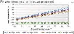
A sample relief calculation for loss of reflux to a de-ethanizer can be used to illustrate the effect of velocity on the pipe temperature (Fig. 1). When the flare header has a velocity of 12 fps (3.6 m/s) and the wind velocity outside the piping is 12 mph (17 km/hr), the calculated heat transfer coefficients are equal inside and outside the piping.
The calculated steady state pipe temperature is the average of the cold fluid temperature and the outside ambient temperature. If the cold fluid temperature is -34° F. (-37° C.) and the cold ambient design temperature is -2° F. (-19° C.), the calculated pipe temperature is -18° F. (-28° C.).
At an ambient temperature of 60° F. (16° C.), the calculated pipe temperature is 13° F. (-11° C.). For an ambient temperature from -2° F. to 60° F. with a wind velocity less than 2 mph (3 km/hr), the calculated pipe temperature is -32 to -33° F. (-36° C.), very close to the inside fluid temperature.
This type of calculation could be used to suggest the following generalities for the relief:
- A loss of reflux relief with any ambient temperature and a wind velocity under 2 mph could result in a piping temperature below -20° F.
- A loss of reflux relief with an ambient temperature above -5° F. (-12° C.) and a wind velocity of 12 mph or greater would not have a calculated piping temperature below -20° F.
- A loss of reflux relief with an ambient temperature above 10° F. (-20° C.) and a wind velocity of 3 mph or greater would not have a calculated piping temperature below -20° F.
Nonsteady state heat transfer calculations
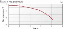
The other factor to consider is the length of time that it takes for the pipe wall temperature to reach its steady state temperature (Fig. 2).
Nonsteady state can be modeled with a dynamic simulation of the system. It can also be approximated by an integration of the system heat balance.10
Equation 4 represents the overall heat balance of the piping system with a cold relief or vent flow. Equation 5 is obtained when it is integrated.
Obviously, piping close to the relief source will more quickly reach steady state than piping further away. The unsteady state heat transfer analysis may have application to a system that has different materials of construction in different parts of the relief system. For example, it took one section of nonimpact-tested pipe that we analyzed nearly 3 hr to reach -20° F. under the most conservative conditions possible.
The relief could continue for more than 45 min only if the operator did not take any action within a 20-min period and the automatic shutdown devices failed to operate properly.
Risk analysis with heat transfer calculation results
The heat transfer and temperature calculations can be input into a risk analysis process to determine if nonimpact-tested carbon steel is suitable for a given set of circumstances.
For the previously mentioned situation, a decision was made that the piping was acceptable based on the following criteria:
- The expected frequency of the relief was less than once per year.
- The ambient conditions that could allow the piping temperature to reach a steady state temperature of below -20° F. occur less than 5% of the time.
- To reach -20° F., the plant operator would have to take no corrective action for over 2 hr, and the plant shutdown instrumentation would have to fail to operate.
- The piping material was not impact tested but may have been able to meet toughness requirements had impact tests been performed.
Liquid relief flows
The heat transfer and temperature analysis showed potential for mitigating circumstances only if the relief or vent flow was 100% gas or vapor.
If the relieved fluid was a cold flashing liquid or mixture of cold vapor and liquid (except in the case of liquid thermal relief), the heat transfer and temperature calculations showed no evidence of mitigating circumstances to be considered for risk analysis.
Acknowledgments
The authors gratefully acknowledge the assistance of Vance Green of Conoco Inc. in reviewing and interpreting B31.3, James Sharpe of Merrick Engineering for taking a lead role in the piping stress analysis work, and Mike Morgan of Conoco Inc. for his review and comments on the original paper.
References
- ASME B31.3-1999, Process Piping, ASME Code for Pressure Piping, B31, An American National Standard, Table A-1 and Figure 323.2.2.
- API Recommended Practices 521, Guide for Pressure-Relieving and Depressuring Systems, Section 3, Fourth Edition, March 1997.
- ASME B31.3-1999, Process Piping, ASME Code for Pressure Piping, B31, An American National Standard, Section 323.3.
- ASME B31.3-1999, Process Piping, ASME Code for Pressure Piping, B31, An American National Standard, Item (l) - Section 302.2.4.
- ASME B31.3-1999, Process Piping, ASME Code for Pressure Piping, B31, An American National Standard, Table 323.2.2.
- 2000 Addendum to ASME B31.3-1999, Process Piping, ASME Code for Pressure Piping, B31, An American National Standard, Table 323.2.2 Notes and Figure 323.2.2B.
- ASME Pressure Vessel Code, Section VIII, Division 1, Paragraph UCS 66.
- Perry, R.H., Green, D.W., and Maloney, J.W., Perry's Chemical Engineers' Handbook, pp. 11-18 - 11-19, Seventh Edition, McGraw-Hill Book Co., 1997.
- Kern, D.Q., Process Heat Transfer, pp. 93-97, McGraw-Hill Book Co., 1950.
- Kern, D.Q., Process Heat Transfer, pp. 626-35, McGraw-Hill Book Co., 1950.
The author
Presented at the 80th annual Gas Processors Convention, Mar. 12-14, 2001, San Antonio. Michael Wilkes is operations engineering supervisor at Conoco Inc.'s San Juan plant at Bloomfield, NM. He has been with Conoco for 23 years in various process and project engineering assignments. Wilkes has a BS degree in chemical engineering from Brigham Young University and an MBA from Phillips University.