Preparedness validated in gulf deepwater flowline repair
Repair of the Macaroni field flowline in the US Gulf of Mexico confirmed for project participants the necessity of adequate preparations in design and equipment.
The Macaroni flowline had been the first J-lay pipe-in-pipe insulated flowline installed in the gulf in July 1999. The line initiated at a subsea manifold in 3,700 ft of water in Garden Banks Block 602 and terminated with a steel catenary riser (SCR) at the Auger tension leg platform (TLP) on Garden Banks Block 426 in 2,980 ft of water.
To limit the consequence of loss of casing-pipe integrity, each flowline was divided into ten bulkhead-isolated compartments each about 6,000 ft long. During construction in April 1999 of the second of two parallel flowlines, the laybarge abandonment and recovery (A&R) cable failed with 3,800-ft of pipe suspended in 3,400 ft of water. The pipe fell to the seafloor, coming to rest aft of the lay vessel in a pile of large loops.
This article discusses the accident and steps used to recover the pipe and resume construction.
Macaroni area
The Macaroni flowline system (OGJ, Mar. 30, 1998, p. 32) was designed and installed to provide reliable transportation for produced fluids from a group of subsea wells in GB 602 to the Auger TLP. The subsea manifold and the Auger TLP are nearly 12 miles apart. Unique features of the system are:
- An insulated pipe-in-pipe system was installed for flow assurance. The insulation minimizes heat loss and maintains the flowing commodity stream at greater than the hydrate-formation temperature with some time allowance for shut-in.
- Dual flowlines were installed to permit pigging and commodity displacement in the event of an extended shut-in.
- Because the insulated annulus is at atmospheric pressure, the flowline pressure design could not take credit for external hydrostatic pressure as in typical deepwater pipelines. The casing is designed for collapse.
- The division of each insulated flowline compartments separated by steel bulkheads was to limit the consequence of loss of casing integrity.
- The flowline system was installed by J-lay to facilitate pipelay start-up (a connection sled was pulled in and pipelay initiated beneath an operating drill rig), minimize top tensions, minimize installation bending strain and facilitate SCR fabrication and hand-over to the Auger TLP.
Fabrication and construction of the system entailed numerous new activities:
- Design of forged bulkheads.
- Design of sliding pipe-in-pipe assembly method, including precise dimensioning to permit operation of automatic welding machines and automatic ultrasonic testing scanners.
- Onshore insulation of double joints with polyurethane foam.
- Onshore fabrication of pipe-in-pipe J-lay "quad joints," prefabricated stands of pipe consisting of four 40-ft pipe joints and forged support collars. The J-lay barge was designed for 165-ft long quad joints.
- Upgrading of the J-lay system for pipe-in-pipe and an increased top tension design load of 775 kips for this and future projects. (1 kip = 1,000 lb)
- Upgrade A&R capability to 490 kips.
- Design of repair and recovery contingency equipment for pipe-in-pipe.
The last item is an essential component of any pipeline construction plan. Repair of damage to the work in progress is never welcome, but a plan must be in place.
In the case of deepwater flowlines and pipelines, job-specific tools are usually needed because of the unique nature of the facilities and the high suspended-span top tensions, particularly if the pipeline must be handled in a flooded condition.
The pipeline
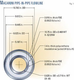
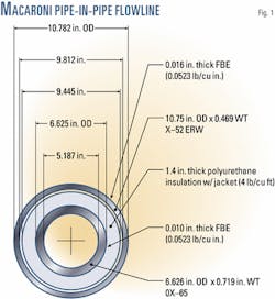
The inside conduit (the flowline) was 6.625 in. x 0.719-in. WT API 5L X-65 seamless pipe. The outside conduit (the casing) was 10.75-in. x 0.469-in. WT API 5L X-52 HF-ERW (high frequency electric-resistance welded) pipe. The annulus was insulated with 1.4-in. of 4 lb/cu ft polyurethane foam (Fig. 1).
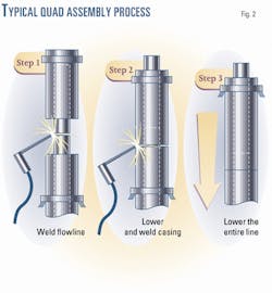
The pipeline was assembled with a sliding system with no metallic parts between the flowline and casing pipes. This was specified to maximize the overall efficiency of the insulated system (Fig. 2).
There was a structural linking of the inside and outside pipes, albeit not metallic. Before welding of the flowline began, about 3 gal of two-part polyurethane polymer was poured into the annulus between the foam insulation and the outside pipe. There was a foam stop about 10 ft down the annulus to limit the annulus length to be filled.
This material set up in a few minutes and locked the pipes so they would operate as a unit. The foam insulation remained intact; the only effect on the heat loss was replacement of about 10 ft of annulus free-air space with solid plastic.
Note that, before the polyurethane was poured, that the weight of the entire suspended span was supported by the outside pipe and that the inside pipe was only loaded with the self-weight of a single quad. To offset the stretch in the casing and keep the stick-up of the inside pipe consistent, Bayou Pipe Coating, New Iberia, La., fabricated the quads with the inside pipe 0.5 in. longer than the outside pipe.
Once in the field, every sixth pipe on average required a slight trim on the ready rack to the inside or outside pipe to bring the inside pipe stick-up back to tolerance.
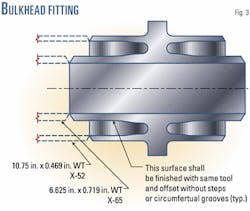
The shear strength of the foam and the polyurethane annulus fill locked the pipes but in no way inhibited flooding of the annulus if casing integrity was lost. The quads were 165 ft long and every 37th quad was a steel bulkhead quad that totally isolated adjacent annular compartments. This computes to a bulkhead interval of 6,105 ft (Fig. 3).
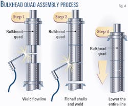
In this type of quad, the casing could not slide down for girth welding. Welding in half shells completed the casing after the flowline girth weld (Fig. 4). Cost optimization established the length of the compartments.
The longer the compartments, the fewer the number of bulkhead quads required, so that the cost of bulkhead quad fabrication and installation went down with increased spacing.
On the other hand, the longer the compartments, the longer was the length of contingency pipe required to replace a compartment. The pipe order included enough pipe to replace a compartment.
The breakeven cost was a bulkhead every 37 quads considering out-of-pocket cost with no risk factoring.
Abandonment, recovery
There were two pipe-abandonment-and-recovery (A&R) systems on the barge.
The primary system was a deck-mounted traction winch and storage reel fitted with 4.25-in. wire rope. The weight capacity of this system was 490 kips and included allowances for sheave friction.
This was adequate for the 420-kip contingency weight of the suspended flowline in the flooded condition. This system was not routed through the J-lay tower due to tower-strength constraints. A single wire run through a crown block has the effect of doubling the crown block load. The main A&R wire, therefore, was routed overboard at a point below the J-lay tower.
For the 775 kip J-lay tower design case, the pipe in the J-lay tower was handled by a single-part sling rigged to the traveling block. At a point below the tower, the pipe would be handed off to the A&R system for abandonment.
The only disadvantage of this system was the considerable time required to rig the pipe for abandonment and then hand it off to the main 4.25-in. A&R system.
As a secondary A&R system, the J-lay tower was fitted with a 27/8-in. A&R system with a capacity of 300 kips. This had been adequate for earlier projects such as the Auger export pipelines.
The Macaroni dry pipe suspended weight was 240 kips; so that if a dry pipe was being handled, the weight was within the limits of this alternate system. This was the preferred mode of handling given the savings in rigging time and the reduced personnel exposure to rigging activities.
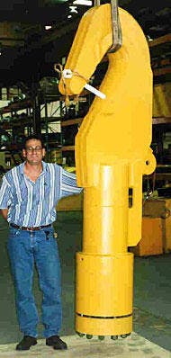
To connect the rigging to the pipeline, a large hook (Fig. 5) was secured to the pipe with a mechanical collet connector that gripped and sealed over the casing pipe. The mechanical system was selected over welding because the collet would leave the casing bevel ready for prompt resumption of pipelay.
Dropped pipe
At the time of the incident, the pipe was suspended with the top of pipe just below the keel of the barge. There had been a weather interruption that the barge was able to ride out by lowering the pipe below the stinger and weathervaning to reduce environmental forces on the beam.
Steps were under way to recommence pipelay operations. The pipe was suspended on the 27/8-in. A&R system and was being drawn up into the J-lay tower for resumption of pipelay. Suddenly, the 27/8-in. A&R cable parted high in the tower and the entire suspended span was lost.
Post-incident analysis showed that the cable parted due to fatigue. The crown block was not a single large sheave but a series of seven small sheaves arranged in an arc, referred to as a "knuckle sheave." The cable had crossed the gang of small sheaves approximately 14 times during 7 earlier A&R sequences.
Unusual features of this cable break were that the independent wire rope core (IWRC) was broken at several locations and the outer cable strands had broken valley wires. This is in contrast to ordinary cable wear in which the outer wires abrade and break.
Assessment
After the pipe was dropped, a remotely operated vehicle (ROV) was immediately deployed to assess the situation. Some 4 hr after the incident, visibility was still substandard. The water was cloudy with fine grain sediments kicked up by a 250,000 lb of steel landing in a heap.
As visibility cleared, the pipe was followed and a map was generated. In Fig. 6, there are several key components noted:
- Top of the pipe (quad No. 200). This was fitted with a collet-locking A&R hook that weighed 5,500 lb and was buried in the mud.
- Buried buckle (quad No. 190). The pipe had buried itself deep under the mud. Ultimately, it was discovered that this was the only location where the casing buckled and developed a through-wall break.
- Bulkhead (quad No. 186). If casing integrity could be maintained from south of this point, we could avoid having to replace pipe due to flooding all the way back to the next bulkhead quad (No. 149).
- Bottom of the span (quad No. 176). This was the pipe that had to be brought to the surface with a dry annulus to continue pipelay.
- The location of the J-lay pedestal at the time of the incident. Note that all pipe came to rest well aft of the vessel. In effect the pipe fell through the existing "hole in the water."
To assess the integrity of the pipe and casing, an ROV deployed a flooded-member detector. This device has a small radioactive source and Geiger counter mounted on a fork. The counts are proportional to the average density of whatever is between the forks and thus interrupts the radioactive beam.
The detector was calibrated on the west flowline, which was believed to be dry. One loop of the dropped east flowline had crossed over the west flowline, but ROV inspection could detect no damage.
The first survey with the flooded-member detector, on Apr. 18, 1999, found both the bore and annulus to be dry. There was a chance the hook could be snagged and the entire span lifted back to the surface.
Plans were progressing when on Apr. 20 the dynamically positioned lay vessel suffered a thruster failure. It would be 15 days before heavy-lift field operations could resume.
During this time, the ROV vessel dredged to uncover and inspect the dropped pipe. The flooded-member detection survey was repeated with ambiguous results. The bulkhead was holding, from quad No. 186 back, all readings showed the line was dry. All pipe from quad No. 177 to No. 186 was exposed and only exhibited smooth bends.
From No. 186 to No. 200, the detector found sections with indications of flooded annulus, flooded annulus and flooded bore, and dry sections. It was hard to imagine that with greater than 1,500 psi of hydrostatic pressure, any defect would not quickly flood the pipe annulus.
Rigging for recovery
There were two configurations for pipe capture.
The first was to capture the A&R hook that was fitted to the top of the span. For this, a master link deployed on the 4.25-in. A&R wire would be set in the hook by ROV and the span lifted. The hook was rated for 400 kips and had been proof tested to 600 kips.
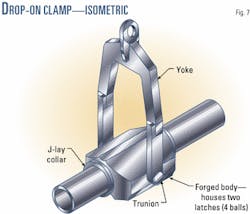
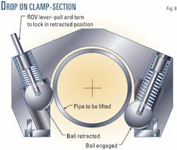
The second was a drop-on clamp that had been designed and fabricated as part of the project's contingency activities. The clamp would be deployed on the 4.25-in. A&R wire, dropped on the 10.75-in. casing pipe with ROV assistance where it would be free to roll until it encountered a J-lay collar. With the J-lay collar bearing on the drop-on clamp, the entire span could be lifted. The drop-on clamp was rated for 400 kips and had been proof tested to 600 kips (Figs. 7 and 8).
The primary A&R had a capacity of 490 kips and was adequate for all recovery configurations. After lifting by A&R to a point just below the keel, the suspended span could be handed to the J-lay tower A&R sling with a capacity of 775 kips or to the derrick auxiliary hoist, which had a capacity of 1,100-kips.
Consideration was given to drawing the damaged line into the J-lay tower, but this was judged unacceptable for two reasons:
- The recovered joints would be bent, and the tower would only accommodate straight pipe. Damage to the J-lay tower would impede completion of the project.
- The joints were to be cut remotely using high pressure water-entrained abrasive. Any scattering of abrasive could damage precision equipment in the J-lay tower.
The J-lay tower was on the starboard side of the barge. For the recovery, a short tower used for assembling TLP tendons was installed on the port side of the barge (Fig. 9). The tendon tower frame had the following benefits: - The tendon tower was within the radius of the derrick auxiliary hoist.
- The tower had a deck level foundation where the J-lay collars could be landed to carry the weight of the suspended span while the quad held by the derrick could be cut free.
- The tower had an upper work platform where the suspended pipe could be dogged off for control upon severing from the pipe below.
- The pipe to be cut off would be suspended in the open air and free to distort.
- The remote abrasive cut would be made away from sensitive equipment.
The recovery would proceed with a hand-over-hand methodology. The J-lay collar would not be set directly onto the tower foundation but instead would be landed in an elevator with a gate and two lifting pad eyes. After the upper pipe was cut and cleared, the elevator would be rigged to the derrick for the next sequence. Two such elevators were used in rotation.
For underwater pipe cutting, an ROV deployable two stage shaped-charge device had been developed and tested as part of the project's contingency engineering.
The first stage was a charge consisting of two 10.75-in. diameter girth cutters connected by two 12-in. long longitudinal cutters. This charge would cut and separate the casing into two removable half shells. It was termed a "window cutter."
The second stage was a 6.625-in. girth weld cutter that would sever the flowline.
For surface cutting, the equipment selected was a high pressure water-jet system with entrained garnet abrasive. The cutting jet was deployed on a remotely controlled powered bug mounted on a band that circled the pipe. In one circular pass the abrasive water jet would cut the casing and flowline cleanly through with no hazard to personnel.
Recovery
Beginning on May 4, the first recovery sequence was to deploy a 6-in. master link on the A&R wire and acquire the A&R hook. There was some doubt about the integrity of the line, but all pipe had been inspected except for the buried section at quad No. 190. What was visible appeared to be fit for tension load.
The master link successfully captured the hook, and the lift commenced. The barge maneuvered to maintain a smooth sag bend at the seafloor; the A&R load was monitored.
All was well with more or less constant unit weight until the touchdown approached the buried buckle at quad No. 190. Here the load and calculated unit weight suddenly increased. The smooth sag bend became a dogleg and the pipe parted.
It was decided to move the barge clear of the right-of-way and continue the recovery. This would leave a clean right of way and give the crew some lifting, cutting, and stacking practice before attempting recovery of the critical reach from quad No. 186 back.
There was concern that the inside pipe might fall free from the vertically suspended 10 quads. The buckle at the bottom, however, was sufficiently bent to keep the inside pipe locked in place. The suspended pipe was transferred to the auxiliary hoist; the upper J-lay collar, directly under the A&R hook, was landed on the tendon tower foundation; and the subsequent hand-over-hand recovery proceeded with no problem.
After the first couple of quads, the recovery time settled in at about 1.5 hr/quad.
The first recovery task was to cut the pipe just above the bulkhead at quad No. 186. The first-stage window cutter was deployed and fired. The cut was a bit ragged and it was only possible to remove one half shell. It would not be possible to fit the second stage girth weld cutter on the flowline.
With operations underway, there was no time to make up another set of shape-charge cutters. The ROV's hydraulic-powered grinder was deployed to cut the pipe with a pair of 14-in. diameter by 1/8-in. thick abrasive disks. The disks were sandwiched together on the tool arbor to enhance the durability of the abrasive wheel. It took several dives, but over the course of a night the ROV was able at last to complete the cut.
With the first reach recovered and the pipe cut at quad No. 186, there was a 500-ft long (three quads) loose section across the ROW. In this case, there was no way to engage the top of the section and have the drop-on clamp yoke hinge over properly. In addition, there was no way to keep the inside pipe from falling free during a recovery.
Prudence required this section be pulled out of the way and abandoned. The drop-on clamp was used to latch on the section, and it was dragged out of the way without the yoke hinging over. The latching balls were then retracted by the ROV to release the drop-on clamp. This also served as a practice run with the drop-on clamp and it worked perfectly.
The barge shifted to a position over quad No. 186, and the drop-on was lowered and latched on the pipe. Again the barge was maneuvered while pipe was lifted to maintain a smooth sag bend. The A&R weight was monitored to assess casing integrity. The bore was 100% flooded and any sudden loss of casing integrity would show as a step change in A&R load.
The top of the reach was successfully brought to the surface and transferred to the auxiliary hoist.
The clamp was landed on an elevator positioned on the foundation fork of the tendon frame. Pipe was cut back to quad No. 177. The last quad removed was curved with a straight tail, which indicated the entire damaged reach had been removed. The A&R hook was used to transfer the pipe back to the J-lay tower.
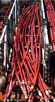
The pipe recovered was returned to shore and transferred to a scrap dealer for recycling (Fig. 10).
Pipelay recommenced on May 10. By May 12, 1999, the project was back to the progress milestone at which the incident occurred.
What was learned
It is prudent to have a plan and equipment in place to effect a repair to the work in progress. The remote worksite requirements (far offshore and thousands of feet down) and the weight of suspended pipes in deepwater call for unique tools that take time to design and fabricate.
Items to acquire are:
- Pipe cutting equipment.
- Pipe capture and lifting equipment such as the drop-on clamp.
- Hoisting equipment capable of lifting the line in the flooded condition (or a dewater plan and equipment that will permit a void lift).
Tools acquired for construction contingencies can also be important in effecting repairs during the operating life of the pipeline.
Also, the dropped pipe incorporated a buckle in the 10.75 in. x 0.469-in. WT X-52 casing that would have progressed as a running buckle if the casing were a plain pipe. The very stout internal flowline prevented the casing from assuming the classic "dog bone" cross-section shape and a running buckle did not occur.
Moreover, in the case of the dropped Macaroni pipe and an earlier event at Mensa, the pipe landed aft of the lay vessel. This was with near-vertical pipe top angle; the Macaroni line was installed with a tower angle of just 5° incline from vertical. It follows that lay vessels can safely approach and transfer steel catenary risers to facilities located above critical installations.
The Macaroni parallel flowlines were separated by 200 ft. One loop of the dropped pipe actually fell across the previously installed line. No damage occurred, but if the incident had happened with the West line, the loop would have fallen over the electro hydraulic umbilical and not a pipe. Separation by 1/10 of the water depth would have eliminated contact with the companion flowline.
The economic cost of dropped pipe incident amounted to approximately 10% of the Macaroni project flowline costs. Due to the advance design and procurement of key repair components and pipe materials there was no schedule time lost apart from the actual repair operations. Twenty-three quads (3,800 ft of pipe) had to be replaced.
Based on a presentation to the Offshore Technology Conference, Houston, Apr. 30 - May 3, 2001.
The author
Robert T. Gilchrist Jr. is an independent offshore pipeline engineering consultant. He was a senior staff engineer with Shell Deepwater Development Systems Inc., Houston, when the work described here took place. He joined Shell in 1978 and undertook assignments with Shell Pipeline Corp., Shell Oil Products, and Shell Development Co. From 1993 to 1996, he was head of underwater engineering for Shell Expro in Aberdeen. Gilchrist holds a BS (1968) in chemistry from Colorado State University at Fort Collins, and an MS (1978) in civil engineering from the University of Wyoming, Laramie. He is a registered engineer in Texas and Colorado.
