Advanced control project stabilizes delayed coker, increases throughput
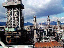
Koa Oil Ltd. improved operations and increased its coker feed rate by applying model predictive control technology combined with an inferential coke-yield model to its No. 2 delayed coking unit at the Marifu refinery, Iwakuni, Japan. - Advanced process controls stabilized Koa Oil's Marifu refinery's delayed coker operations and increased the unit output. Photo courtesy of Koa Oil Ltd.
The company initiated this project in 1999 as part of an advanced process control (APC) program to install model predictive controllers (MPCs) on all major process units at its Osaka and Marifu refineries. It signed off and accepted the project in June 2000.
Koa first applied the APC program to the delayed coker in Marifu because of its high economic potential. The main objectives were:
- To maximize unit throughput subject to minimum coking drum-outage limits and unit operating constraints.
- To adjust the feed blend so that the unit operates at the maximum sulfur-in-coke limit.
- To control and improve product quality and stabilize main fractionator and gas-plant debutanizer operations during major drum events.
The advanced control project increased the coker feed rate by 2.5% by operating the unit closer to the minimum drum-outage target.
The inferential model and the predictive controller use online operating data to predict the coking-drum outage. A good estimate of the outage allows the APC to determine the maximum safe feed rate to operate the unit within constraint limits and maintain products on specification.
The estimation of coke yield is based on actual drum temperatures, pressures, recycle ratio, and a feed-coking factor that is calculated with an online density analyzer. The use of an online density analyzer to characterize the feed quality enhanced the coker's performance under closed loop control of the unit feed.
Coker process
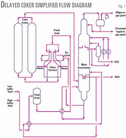
Koa's No. 2 delayed coker consists of a main fractionator, a gas plant, a set of coke drums, and a furnace. Fig. 1 is a simplified flow diagram of the No. 2 coker without the gas plant.
A blend of low and high-sulfur feed components combines with recycle oil and steam in the furnace. The furnace heats the feed to a maximum operating temperature and sends it to the bottom of the coking drum.
During the coking cycle, coke deposits in the active drum. The drum vapor product separates into offgas, overhead liquid, light gas oil (LGO), and heavy gas oil (HGO) products in the main fractionator.
Product-quality limits include percent of sulfur-in-coke, gasoline Reid vapor pressure (rvp), naphtha end point, and LGO end point. The key process constraints include the minimum drum outage at the end of the coking cycle, furnace-tube metal temperatures, HGO tray level, bottom level, and several temperatures in the main fractionator and gas-plant debutanizer.
The drum events and the injection of condensate collected during the drum warm-up and steam-out events into the main fractionator were major disturbances to the coker operation.
Controller design
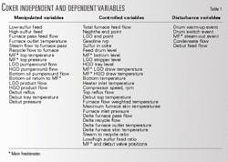
Table 1 summarizes the key manipulated variables (MVs), controlled variables (CVs), and disturbance variables (DVs) related to the coking furnace, main fractionator, and gas plant.
While it would have been possible to build one large multivariable controller to handle such a large problem, Koa engineers implemented three separate multivariable controllers for the three process areas.
The decision to design three separate controllers was based on review of unit operations, control objectives, and step-test results. The interactions among the coking furnace, main fractionator, and gas plant are minor for the Koa No. 2 coker.
The MVs for the furnace controller include the pass flows, outlet temperatures, steam flows, and the low and high-sulfur feed flows. The CVs include the total heater-feed flow, coke quality, combined flow weighted temperature, tube-skin temperatures, and the feed-drum level.
The feed-maximization program calculates the maximum feed safely to fill the coking drum, subject to the minimum-outage operating target and the operating coke-drum cycle time.
The sulfur in coke was calculated based on updated daily lab samples of the high-sulfur feed.
Feed maximization
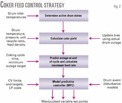
The feed-maximization control strategy for the coker uses a coke-yield program package integrated with a commercial MPC (Fig. 2).
The coke-yield program continuously estimates the current coke yield for the online coking drum based on actual operating conditions and fresh feed qualities. Drum-switch detection logic resets the program variables upon detection of a drum switch.
For a given cycle time and minimum-outage target, the program calculates the maximum coking limit and optimum feed rate. The estimated feed rate becomes the feed CV set point for the MPC. The MPC relaxes the feed target if other feed-related unit constraints become active.
Decreasing cycle time is an operating objective for increasing feed throughput to a coker. Cycle times are fixed in most cokers, however, because the operation of most cokers follows a fixed schedule.
The minimum-outage target represents the coke-drum fill safe limit, which offers the most potential for throughput maximization with a control program.
Coke yield
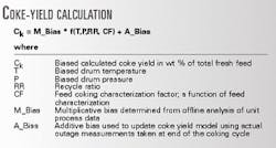
The four-parameter model in the accompanying box determines the coke yield.
The coke yield decreases as the drum temperature increases. If the coking temperature limit is raised too high, the coke will become too hard, which may adversely affect the decoking process.
A decrease in pressure decreases coke yield because more heavy hydrocarbons are vaporized. With a higher pressure, the coke drum would trap these heavier hydrocarbons and convert them to coke and light hydrocarbons.
The recycle ratio has the same effect as pressure on the coke yield.
The coking tendency of the feed expressed as the characterization factor in the box is a function of bulk feed density only. The Koa coker APC project used historical operating data of the actual coke yields, independent variables, and feed density to establish a correlation between the coking factor and the fresh feed density. The coke-yield program used online is also used offline to determine the coking factor and feed density relationship.
An online density analyzer estimates the feed coking factor online. Initial analysis of the operating data showed significant error in the coke-yield calculation.
Collected data concerning the yield prediction and the measured outage indicated the calculation error was a result of inaccurate and infrequent measurements of the feed density.
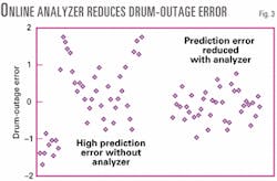
Based on this analysis, Koa installed an online density analyzer to improve the performance of the feed-maximization control strategy. Using an online density analyzer reduced the average residual in the coke yield and drum-outage calculations by 50%.
Fig. 3 shows drum-outage prediction residual before and after installation of the density analyzer.
With improved prediction of the drum outage, the feed target to the coker can be raised to maximize feed and operate closer to the outage limit. For the Koa coker, the average absolute error between the actual and predicted outage is less than 0.5 m.
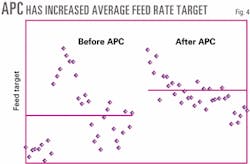
Fig. 4 shows how APC has raised the average feed target. A small increase in unit throughput can result in significant economic benefit because of the high value of incremental feed to the delayed coker.
Outage update
Adjustment of the additive bias term in the coke-yield equation, using actual coke-drum outage measurements taken after each drum cycle, corrects the error in the coke-yield calculation.
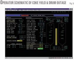
The coker APC project developed a custom DCS schematic (Fig. 5) as the operator interface to display all the key inputs and outputs from the drum-outage calculation.
The operator uses this interface to correct the coke-yield additive bias term using the actual measured drum outage. The ability to correct the yield calculation by simply adjusting the bias term was useful during the occasional periods when the coker produced low-sulfur coke. The bias term can be adjusted before a change in sulfur mode, improving the coke-yield estimate for the new coke batch.
Feed quality
In addition to feed density, Koa measured feed distillation (10%, 50%, and 90%) and feed sulfur content for different coker feed components to verify if the coke-yield calculation could be improved by using additional feed-quality information.
Interestingly, the evaluation excluded Conradson carbon residue (CCR) as a potential input for characterizing the feed quality. There is no clear relationship between the CCR and coke yield for the Koa coker.
While there was an improvement in the coke-yield estimate with additional feed-quality inputs, the small improvement did not justify the added complexity of designing, building, and supporting a multifeed component system to characterize the feed for sulfur, distillation, and density.
The bulk feed density cannot account for all the coking characteristic of the coker feed. There were enough operating data to suggest, however, that the feed-density measurement was sufficient to characterize the coker feed. With the feed density measurement and other operating parameters, Koa could estimate the coke yield accurately enough for closed loop control of the coker-feed rate.
Fractionator, gas plant controllers
The APC project designed and tuned the main fractionator and gas plant MPC programs to maximize product value subject to product quality and unit constraints.
Koa accomplished this by defining a linear-program (LP) objective function to use both manipulated variable and controlled variable pricing. By inclusion of product flows in the objective function, the objective function is formulated as a profit function.
The MVs for the main fractionator MPC include the top temperature, LGO, and HGO product flows, LGO and HGO pumparound flows, and recycle oil flows. The CVs include the naphtha end point, LGO end point, LGO stripper level, HGO tray level, bottom level, and several valve positions and tower temperatures.
The MVs for the gas-plant debutanizer MPC consist of reflux flow, reboiler duty, and top pressure. The CVs include gasoline rvp, top pressure compensated temperature, and several valve positions.
Online measurements calculate the gasoline rvp, naphtha end point, and LGO end point. These calculations are periodically corrected using lab sample results. Prior to the APC project, Koa did not control nor frequently sample the naphtha end point and LGO end point.
Fractionator stabilization
Stabilizing main fractionator operations, particularly during the drum events, was a key control objective. The fractionator is subject to significant transient disturbances during drum events due to the batch nature of the delayed coking process as one drum is filled and the second drum is prepared for coking.
The APC project team modeled the drum events as discrete event disturbance variables so that the controllers could handle these transient disturbances. The team used special logic in custom programs to generate unit step changes in the value of the drum events.
The controllers then respond to the discrete event unit changes to maintain the process at the desired operating limits.
Using process flow, temperature, or pressure as DVs is less effective because these variables change only gradually during a period of several hours after a drum event begins. The use of discrete events as feed forward variables is also better due to the long settling time of the fractionator and gas plant CVs. Modeling the CVs to drum events as discrete events captures the full dynamic information immediately after the drum event occurs.
By providing feed-forward information of the drum events on the process, the multivariable controller is able to make simultaneous adjustments to the pumparound flows and product-draw rates. The coking-drum vapor feed changes in both quantity and enthalpy during the drum switch, and the main fractionator truly becomes a multivariable problem.
Following a drum event, many of the CVs suddenly become active, requiring quick and large moves in the MVs to maintain all CVs within limits.
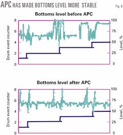
Maintaining a steady inventory of liquid in the main fractionator bottoms was an ongoing operational challenge requiring frequent adjustments to the bottom pumparound section. The main fractionator bottoms level can change very quickly, often as much as 30-40% within several minutes after a drum switch.
As shown in Fig. 1, fresh feed flows directly to the coker furnace and to the coking drums and not to the bottom of the main fractionator as with most conventional delayed coker designs. Unlike most cokers, however, flow-control valves directly control the Koa No. 2 coker recycle oil flows.
While this allowed tight control of the recycle ratio, the small flows and the narrow operating ranges of the recycle-oil flow control valves were insufficient handles to maintain the bottoms level.
The other available independent variable that could affect the bottoms material balance was the HGO product draw flow. However, operators normally used the HGO product draw to control the HGO tray level.
Often the only method for controlling the bottoms level was manipulating the heat balance of the main fractionator bottom section. Obtaining good drum event models was key to controlling the process with the multivariable predictive controller.
In modeling the CVs to the drum event DVs, it must be recognized the CVs will respond differently from drum event to drum event. These various responses occur because the operating conditions around the coke drums vary among cycles.
Some drum switches are more severe, particularly if the drum warm-up time and the offline drum temperatures at the time before the switch are significantly different.
As the response of the MPC-controlled variables to the drum event DVs are not always the same, the drum event disturbances models represent an average of the expected change in the controlled variables to a step change in the drum event DVs.
Three drum events affect the fractionator and gas plant operation:
- Drum warm-up. A significant loss of hot vapor feed to the fractionator occurs when part of the overhead vapor from the online drum is routed to preheat the offline drum. The drum event program detects the warm-up event by monitoring the offline coke-drum overhead pressure.
- Drum switch. When feed is changed from one drum to the other, there is again a sudden large change in vapor feed to the fractionator. As part of the drum switch operation, steam is injected to the full coke drum to remove any hydrocarbons entrapped in the coke matrix. The drum event program detects the drum switch event by monitoring the change in the inlet temperatures of the two coke drums.
- Steam out. The steam that had been sent to the fractionator after the drum switch goes to the blowdown system. The drum event program detects the steam-out event by observing the blowdown tower pressure, steam flow to the full drum, and the time elapsed after a drum switch.
The use of discrete drum events in the MPC design significantly improved control and helped to stabilize the main fractionator operations.
Fig. 6 shows data for the main fractionator bottoms level, a key CV, before and after APC. Before implementation of APC, the level would be allowed to stay at 100% for up to an hour or more. After installing MPC, operators kept the bottoms level within the desired operating range.
The unit step changes represent the drum switches. A key to maintaining all CVs within limits is using range limits instead of specifying targets for CVs. This method allowed the MPC to make better use of the MVs for the highly interactive main fractionator process and modeling errors associated with coker-drum events.
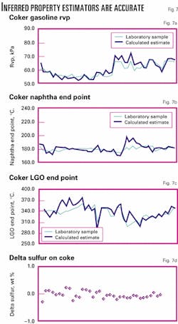
Before the APC project, the refinery did not control the main fractionator product qualities. The project installed inferential property estimators to control the naphtha end point, gasoline rvp, LGO end point, and sulfur in coke.
Figs. 7a-7d show the results of the installed inferred property estimators vs. laboratory samples.
Keys to success
Many factors contributed to the success of the Koa coker APC project, including active participation of personnel from the start of the project, management's commitment to the project, and a well-defined project scope.
Koa engineers with more than 20 years' experience in operations and process control of the coker unit maintain and support the advanced control programs after the project's final acceptance in mid-2000. This ensures the operations staff continues to receive full engineering and technical support to increase utilization of the advanced control programs.
Another key reason for the project's success was the reliability of the instruments and analyzers in the delayed coker area. The refinery routinely checks all critical instruments and analyzers as part of an ongoing preventive maintenance program.
The authors
Arthur I. Chang is a senior consultant at Honeywell Inc., Thousand Oaks, Calif. He has project experience in application of APC in conversion and separation process units including FCC, delayed coking, hydrocracking, reforming, crude and vacuum towers, gas plants, lube plants, and power plants. Before working for Honeywell, he worked for Mobil Oil Corp. where he held various operations and staff positions in marketing, supply, and manufacturing of petroleum products. Chang holds a bachelors in chemistry from the University of Illinois, Chicago, and a masters in chemical engineering from the Illinois Institute of Technology, Chicago.
Keiji Nishioka is the leader of the APC project at Koa Oil, Japan. He is currently responsible for managing the APC project at Koa's two refineries (Marifu and Osaka). Nishioka holds BS and MS degrees in catalytic chemistry from Waseda University, Tokyo.
Takashi Yamakawa has more than 25 years' operations and process control experience, all at the Marifu refinery in Iwakuni, Japan. He was the lead control engineer for the delayed coker APC project. Yamakawa is currently responsible for maintaining, supporting, and improving the advanced controls at the Marifu refinery.
