Innovations key reeled pipe-in-pipe flowline for gulf deepwater project
Four novel components of a reelable pipe-in-pipe flowline system were installed in BP PLC's Nile project in the US Gulf of Mexico in January 2001. Presented here are details of design and qualification testing for the insulation material, pipeline centralizers, buckle arrestors, and reelable water-stops.
The Nile field is approximately 85 miles southeast of New Orleans in Viosca Knoll (VK) Blocks 913 and 914. The field produces primarily gas condensate and will be developed as a subsea tieback to the Marlin tension-leg platform (TLP) in VK 915 in water 3,245 ft deep (OGJ, Feb. 3, 1997, p. 26). The Nile tieback consists of a 7.5-km, 6 by 10-in. pipe-in-pipe connected to a 6-in. steel catenary riser.
The overall heat transfer coefficient (OHTC) requirement for the pipe-in-pipe is 0.21 btu/°F.-sq ft-hr (1.2 w/sq m-°K.). The design temperature is specified as 95° C.
Insulation design
An insulation requirement of an OHTC of 1.2 w/sq m-°K. is particularly challenging. Combining it with a water depth of approximately 1,000 m and the high design temperature limits selection of suitable insulation materials. The design parameters dictated a pipe-in-pipe solution, and it was on this basis that the project was specified.
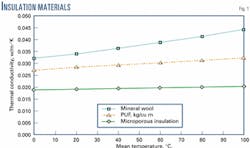
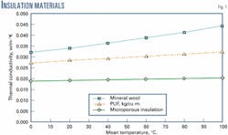
There were three pipe-in-pipe insulation materials considered for these performance requirements: polyurethane foam (PUF), mineral wool, and microporous insulation. Each has specific advantages in terms of insulation performance, operating temperature range, and relative cost. Fig. 1 presents a comparison of the thermal conductivity of each material.
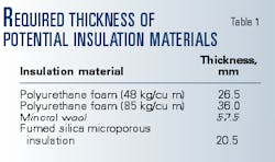
In the course of previous development work by Coflexip Stena Offshore (CSO), each of these materials had undergone both simulated installation and thermal evaluation to assess its suitability. Furthermore, CSO had developed a detailed heat-transfer model that allowed the required thickness of each insulation material to be determined. Table 1 presents a first assessment of required thickness of these materials.
First review of the results made clear that the required thickness of mineral wool is too great for a 10-in. carrier pipe; a 12-in. pipe would be required. Using a larger carrier pipe would increase procurement cost and significantly increase pipe-lay top tension. This option received no further consideration.
Two densities of PUF were considered in the design process. The higher density PUF (85 kg/cu m) would require that almost the entire annulus be filled with insulation. This affects the fabrication procedure. The method of fabrication of pipe-in-pipe employed is to fabricate 1-km stalks of flowline and carrier pipe. The flowline stalks are then inserted into the carrier pipe.
This method allows optimum spoolbase efficiency and removes the requirement for field joints, therefore removing the need for welded half shells or sleeves that may prove problematic during reeling and pipeline operation.
A limitation of this fabrication procedure is that a radial gap is required to allow the insulated flowline to be installed within the outer pipe. An air gap must therefore exist around the outside of the insulation material. The higher density PUF was therefore unsuitable.
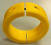
Both the microporous insulation and the low density (48 kg/cu m) PUF options have negligible load-bearing strengths. This must be compensated for by the use of pipe-in-pipe centralizers that are solid polymer rings clamped onto to the flowline (Fig. 2).
While these serve to protect the insulation material during fabrication, installation, and operation, they also increase the heat lost from the flowline. Compensating for the presence of centralizers requires an additional thickness of insulation material. The lower density PUF would need to be increased to 34 mm, a thickness deemed to be too great to allow flowline pull in.
The fumed silica insulation material, therefore, appeared the most suitable for this project. It allowed a relatively large air gap to be maintained ensuring that the insulation material could remain undamaged during pull in, reeling, and operation.
Initially considered was the load-bearing potential of PUF (that is, its use without centralizers). It was thought that a density that could withstand reeling loads could be determined. But significant concern remained over the long-term creep performance of a low-density polyurethane foam.
The flowline within a carrier pipe will tend to "snake" during operation. This snaking results from thermal expansion creating a compressive force in the flowline. Given the slenderness of the flowline, even a slight out-of-straightness, resulting from pipeline self weight, causes this deflection of the flowline. This deflection will cause a lateral load to be applied to the insulation material. It was considered that under the combination of this load and the high temperature that there would be progressive creep of the insulation.
The selected insulation design consisted of a 24-mm thick layer of microporous fumed silica insulation. This is thicker than the insulation thickness noted in Table 1 because of an allowance for heat loss through the centralizers
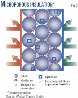
Fig. 3 illustrates the operating principle of microporous insulation. This material owes its extremely efficient performance chiefly to a microporous molecular structure.
The spherical molecules of fumed silica are just in point contact with one another, which minimizes solid conduction. The gaps or micropores between the silica particles are small enough to trap air molecules and prevent them from transmitting heat by convection. The resistance to heat transfer is further reduced by the addition of a carbon-black compound that is an infrared opacifier intended to minimize radiation heat transmission. The resulting material has a brittle chalk-like composition.
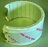
For installing on pipelines, the material comes in closed packages that form pre-shaped panels shown in Fig. 4.
A two-layer insulation system ensures that all seams between consecutive panels are covered by a second layer preventing heat leakage. The consequences of gaps between panels or half shells in a pipe-in-pipe system are well known.
A previous program of thermal measurements showed that an increase in heat loss of up to 20% could be directly attributed to such gaps. To ensure that these gaps do not adversely affect the performance of the insulation system, design of the packaging of the insulation allowed a repeatable good quality of application.
The panels have striations or ribs cut into the inner surface of the panel. This allows them to form a cylindrical shape for pipeline application. An additional benefit is that the striations allow pipe tolerances to be compensated for and panels to be fitted over weld caps.
As stated, the material has a weak chalk-like structure and little handling strength. The packaging therefore comes vacuum sealed to provide some strength to the panels. This vacuum packaging increases the panel curvature (helps close gaps between striations), provides protection from moisture ingress, and limits the risk of particle inhalation during handling.
A further benefit of sealing the panels at a pressure less than atmospheric is that the thermal conductivity of the insulation material is reduced. This effect is not accounted for in the design because the packaging is permeable to all but the largest gas molecules and any benefit from the vacuum would be lost prior to operation of the pipeline.
As a result of their packaging, the insulation panels are fabricated to pre-specified dimensions. The lengths of the panels are selected to fit into the spacing between two consecutive centralizers and to ensure that heat leakage is limited. The first and second layers are made up of multiple panels of different lengths to allow overlapping of panel seams.
Pipe-in-pipe centralizers
Fig. 5 shows a centralizer whose outer diameter is the largest possible that can pass through the combination of worst-case pipeline tolerances specified in API 5L. Following this conservative approach for the Nile pipeline, the largest possible centralizer OD required a diametrical clearance of approximately 15 mm.
The requirements of the Nile project resulted in 400-m stalk lengths: 400-m lengths of flowline inserted into carrier pipe of the same length.
The first function of the centralizer is to ensure that the insulation material remains undamaged during this assembly. The thickness of a centralizer must therefore be sufficiently greater than the insulation to prevent the material becoming snagged on any weld penetrations.
A further consideration during pull in is the shear load applied and the clamping force required to prevent centralizer slippage during pull through. Centralizer slippage would have a significant consequence during pull. Stuck pipe would cause disruption to fabrication and would require stalk lengths to be cut and disassembled resulting in damage to, and loss of, material.
Reel ship installation of a pipe-in-pipe system results in particularly complex flowline-carrier pipe interaction during reeling. A detailed finite-element model has been developed specifically for the purpose of understanding this interaction.1 The centralizers transmit the bending load from the carrier to the flowline, which requires high compressive strength.
An equally important consideration during reeling is the spacing of centralizers. Selection of the correct centralizer spacing will prevent the insulation material being crushed excessively.
During operation, the carrier pipe resists thermal expansion of the flowline. This results in a snaking of the flowline within the carrier pipe. The centralizers control the amount of deflection that will occur. While the resulting contact loads are not particularly high, the combination of loading and high temperature leads to the tendency for the centralizer material to creep over time. Creep resistance is therefore a functional requirement for centralizers.
These design requirements can be summarized as a material that has good abrasion resistance and high compressive strength and is creep resistant. A material that meets these requirements is Poly- amide 6.
There is a further requirement that the material should not contribute to a substantial heat loss from the pipeline. In terms of insulation performance, the centralizers are comparatively poor, having a thermal conductivity around ten times that of the insulation material.
As they meet the mechanical requirements, however, this heat bridge can be compensated for by addition of extra insulation material that is insignificant when considering the comparatively small surface area the centralizers will cover.
The final design consisted of 24 mm of microporous insulation and Polyamide 6 centralizers spaced at 2 m intervals.
Insulation qualification
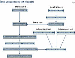
Fig. 6 summarizes the qualification program performed on the insulation and centralizers.
- Application trials. The purpose of the application trial was to construct a test sample with project-specific materials and procedures. This test piece then provides the basis for further testing work such as installation trials and thermal evaluation.
The application trials define the standard of application of insulation panels that must be achieved in production. A detailed dimensional survey of the insulation and a photographic record of the test piece were made.
- Reeling trials. The Nile pipe-in-pipe was installed from the reel-lay vessel CSO Apache.
The most onerous loading conditions during installation occur in the reeling and unreeling of the pipeline. To simulate this loading, a trial used the bending rig facility at Heriot Watt University, Scotland.
The pipe-in-pipe was subjected to two complete bending cycles: bending of the test pipe first onto the reel former (8.23 m radius simulating the CSO Apache reel) and then onto the straightening former (55 m radius, simulating the CSO Apache straightener).
- Insulation-only confirmation. The procedure and equipment used to confirm the OHTC of a pipe-in-pipe were specifically developed by CSO.2 Assessment of the OHTC value requires two phases of measurements.
First, determining the heat transfer through the insulation material alone establishes if there has been material damage during reeling. The second test then assesses the actual OHTC value through the combination of insulation and centralizers.
The first test, assessing the OHTC value without pipeline centralizers, consisted of measurements taken at three temperatures; 105° C., 120° C., and 130° C. The OHTC values measured were consistent with each other and equal to 1.0 w/sq m-°K. This corresponded well to the predicted OHTC. It was concluded that a good quality of application had been achieved and that the performance of the insulation material was unaffected by the reeling trial.
- OHTC confirmation. With the insulation material performing as predicted, it was then required to assess the effect of the centralizers and determine if the final OHTC would meet the project requirement. Thermal measurements were performed at flowline temperatures of 70°, 95°, 105°, and 120° C. A maximum average OHTC of 1.16 w/sq m-°K. was measured during the second test series.
It was therefore demonstrated that the long-term insulation performance of the pipe-in-pipe met the Nile project requirements. The presence of centralizers affected the pipe-in-pipe OHTC by about 15%.
- Post-test visual inspection. Following the thermal test, carried out at a higher temperature than expected during pipeline operation, the pipe-in-pipe sample was dismantled for inspection of the insulation. The visual inspection confirmed no damage to the insulation during the test program. A repetition of the dimensional survey turned up no signs of insulation compression.
Centralizers' qualification
A centralizer abrasion test was to demonstrate the reduction in thickness that would occur as a result of centralizers passing over carrier-pipe welds during pipe-in-pipe assembly. Centralizers were fitted onto a 6-in. pipeline and pulled back and forth through a 10-in. carrier-pipe joint that included an exaggerated 3-mm-high weld penetration.
The number of weld passes in the test was greater than the maximum number of weld passes the leading centralizer would make. Inspection of the centralizers carried out following the test showed that although there were some deep scars, the general level of abrasion was acceptable and less than 1 mm. These centralizers were then re-fitted to the flowline and used in the reeling trial
The abrasion test centralizers were included in the insulation reeling trial. Visual inspection revealed no signs of mechanical deformation.
There is a risk that centralizers may slip out of position during the flowline pull in operation. This was of particular concern because the flowline was externally coated with fusion-bonded epoxy (FBE), which had a low coefficient of friction.
A slippage test was performed to determine the load at which a centralizer would slip. The acceptance criterion was negligible displacement, that is, less than 1 mm, for the predicted pull load. The centralizer initially failed this test and was unable to withstand this load without slipping.
As a result, the bolting arrangement was redesigned to allow a higher level of bolt torque to be achieved. On completion of this modification, the test was repeated and the centralizer passed the test.
As outlined previously, the centralizers will support the flowline during operation and therefore may tend to creep over time. It is required that this level of creep not lead to the insulation material becoming compressed. A creep test was performed.
A centralizer was inserted between a section of flowline and carrier and then heated to 95° C. A compressive load was then applied and held for 625 hr. The reduction of centralizer thickness was constantly monitored during the test.
Plotting short-term creep on a logarithmic scale made it possible to predict the level of creep over the pipeline lifetime. A lifetime creep of 0.85 % of the centralizer thickness was calculated. Centralizer creep at the end of the design life was therefore considered negligible.
This testing revealed a cumulative reduction in centralizer thickness of less than 1.3 mm, significantly less than the acceptable maximum. BP therefore accepted the centralizer for the Nile project.
The centralizer design was 7.5 mm thicker than the insulation. A portion of this height was sacrificial to account for potential reduction of the centralizer thickness throughout fabrication and service life. It also provides sufficient gap to prevent insulation compression during reeling. The test results demonstrate that this difference of thickness could be reduced further allowing a thicker layer of insulation that would achieve an even lower OHTC value.
Buckle arrestors
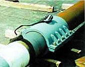
The carrier-pipe wall thickness is designed against collapse but not buckle propagation. Buckle arrestors are therefore required to limit the consequences of a propagating buckle. Clamp-on buckle arrestors (Fig. 7) were considered to be the most suitable option for reel-ship installation because they are installed after the reeling process is complete.
Traditional designs, such as thick-walled integral buckle arrestors, constitute an increase in bending stiffness and would cause buckling of the host pipe during reeling. The arrestors were designed following recommendations published as a result of an experimental program.3 Design and qualification of these buckle arrestors are covered extensively elsewhere.4
The buckle arrestors were subjected to full scale quasi-static propagation testing. It was required to show that the buckle arrestors could resist propagation of a buckle driven by a hydrostatic pressure of 100 bar.
The test consisted of placing a full scale pipe-in-pipe sample within a pressure vessel. Applied external pressure collapses the carrier pipe, and a buckle propagates. The buckle arrestor then arrests the propagation. External pressure is increased to reveal at what pressure the buckle arrestor will fail and the buckle will "cross over." The acceptance criterion set was a crossover pressure of 150 bar (1.5 times the hydrostatic pressure). Each test exceeded this value.
Further details on the qualification of reelable buckle arrestors are available.4
Water-stops
The pipe-in-pipe was to be fabricated in a continuous length without field joints or bulkheads. There was therefore a risk that in a mishap, such as an anchor impact or dropped object breaking the carrier pipe, the complete annulus would become flooded. Performance of the insulation material would be severely impaired if flooded.
The flow analysis performed by BP indicated that the pipeline could operate satisfactorily for much of its service life if the flooded section of the pipeline could be limited to 400 m. To this end, water-stops were required to limit the damaged length.
Water-stops are required to resist flooding of annulus at any time in the lifetime of the pipeline and should be able to retain a sealing effect for the entire pipeline life. The design requirement specific to reeling is that there should be sufficient flexibility to allow onshore fabrication and reeling.
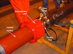
Water-stop design is based on the lip-seal concept (Fig. 8). The seal is energized if the annulus becomes flooded. When pressure is applied, the water-stop lips are forced into the annulus walls, creating a seal. The reason for selecting this concept is that the seal is not energized until required, ensuring that the seal exists in an unstressed state until activated by a flooded annulus.
The complete water-stop design is an assembly of three components (Fig. 8).
The seal itself is polyurethane consisting of the lips, which allow the seal to become energized, and the main body, which is stiffer and provides strength.
Under application of a hydrostatic pressure of 10 MPa, the water-stop would be pushed down the pipe-in-pipe annulus. To overcome this, a forged ring is welded in line with the flowline to act as a backstop. This ring has a larger outer diameter than the flowline and prevents the water-stop sliding under pressure.
The inclusion of this forged piece raises concerns about the reelability of a stiffer section in the pipeline. The solution was to create a relatively small increase in diameter for the forged piece and to bolt steel rings on either side of the forging.
These rings are a relatively loose fit on the pipeline and do not contribute to bending stiffness. But they have an outer diameter large enough to support the water-stop. The forged ring is then small enough not to affect reeling integrity. Finite-element analysis showed no significant increase in stress during reeling.
A further design detail is that the flowline outer surface and the inner surface of the carrier were blasted and painted to provide a good surface against which the lips could seal.
Water-stop qualification
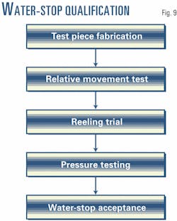
Fig. 9 summarizes the qualification program.
- Water-stop abrasion test. It is known that there may be slight relative movement between flowline and carrier during reeling. A section of 6-in. flowline including centralizers and a water-stop was prepared. The flowline was partially inserted into a joint of 10-in. carrier pipe. The internal surface of the carrier pipe had been sand blasted and painted with an epoxy primer.
The water-stop was pushed 5 m inside the carrier pipe, as it entered the pipe, the lips made contact with the carrier pipe's inner surface. The water-stop was pulled out of the pipe and the lips inspected for damage. This procedure was repeated six times with inspection of the sealing surfaces after each stroke. No damage or abrasion of the sealing surfaces was observed.
- Water-stop reeling trial. To reproduce the strain experienced by the water-stop during the reeling, a 12 m long test pipe-in-pipe including a water-stop was assembled for a bending trial. The pipe-in-pipe was subjected to two complete bending cycles. A visual inspection of the water-stop before the first pressure test revealed no damage to the sealing surfaces, the mechanical connection, or the forged piece.
- Water-stop pressure tests. Four pressure tests were carried out in order to qualify the water-stop. The first three tests used same water-stop from both the abrasion test and the reeling trial. The final pressure test used a new seal.
The pressure vessel for the test was constructed by welding flanged ends to the section of pipe-in-pipe cut from the reeling string. This test section contained the reeled water-stop.
Heating of the outside of the carrier pipe achieved the test temperatures. A temperature probe for water temperature inside the flowline and thermocouples fixed to the outside of the carrier pipe measured the temperature of the test rig.
The four pressure tests were intended to simulate the various possible pressure and thermal loadings that could be applied to the pipeline throughout its lifetime. The maximum pressure applied to the water-stop was 182 bar at a temperature of 95° C. and held for 24 hr. In addition, a cyclic pressure test simulated a successive number of start-ups and shutdowns.
The water-stop was accepted because it passed the abrasion, bending, and pressure tests. It was therefore demonstrated that the water-stop could be reeled and could seal under a combined pressure of 182 bar and temperature of 95° C. and under different operational constraints.
Arrestor, water-stop operating principle
The spacings of buckle arrestors and the water-stops need to be considered together. While it was specified that the water-stops should be spaced at 400 m, their arrangement required careful consideration.
The water-stops are unidirectional; that is, they can only resist water ingress from one direction. The assemblies were therefore installed in pairs facing each other; this arrangement can resist flooding from either direction.
The positioning of the buckle arrestor in relation to the water-stops is important to ensure that the water-stops remain undamaged in the event of a propagating buckle. The buckle arrestor is positioned midway between the two water-stops. Fig. 10 presents the arrangement.
The logic behind the arrangement can be explained as follows: In the event of a buckle, the carrier pipe between two buckle arrestors will be heavily deformed; water-stops within this section can be assumed to be damaged and inoperable. If this buckle creates a leak, water-stops will then be required beyond the buckle arrestor clamps to limit the flooded section.
Acknowledgments
The authors thank Wacker Chemie GmbH, Antoine Bastard (Coflexip Stena Offshore), and BP for allowing publication of the Nile test program. Water-stop design details are published with the permission of Tekmar UK Ltd.
References
- Suschitz, Luca, "A Reeling Study for Ultra Deep Water Vessel Development," DOT 2000, New Orleans, Nov. 7-9, 2000.
- Nuttall, Robert H., and Rogers, Maurice G., "Insulated Pipe-in-pipe Subsea Hydrocarbon Flowlines," OMAE 1998, Lisbon, July 6-9, 1998.
- Langer, Carl G., "Buckle Arrestors For Deepwater Pipelines," Offshore Technology Conference, Houston, May 3-6, 1999.
- Bastard, Antoine H., "A New Buckle Arrestor For Reeled Pipe-in-Pipe," ISOPE 2000, Seattle, May 28-June 2, 2000.
The authors
Gordon Tough joined the offshore engineering division of CSO in 1997 and has worked in the rigid pipeline development group for 4 years. He graduated with BEng (honors; 1995) in mechanical and offshore engineering from the Robert Gordon University, Aberdeen.
Sylvain Denniel joined the offshore engineering division of CSO in January 1997, spent 2 years as a geotechnical engineer, and has since joined the rigid pipeline development group. He graduated as civil and environment engineer (1995) from the National Institute Of Applied Sciences (INSA), Rennes, France.
Abdulmajid (Majid) M. Al-Sharif is a consultant project engineer with J P Kenny Inc., Houston, specializing in deepwater pipelines design and construction. He holds a BS in mechanical engineering from KFUPM, Saudi Arabia, and MS and PhD in mechanical engineering from the University of Pittsburgh, Pittsburgh, Pa.
Based on a presentation to the Offshore Technology Conference, Houston, Apr. 30-May 3, 2001.
