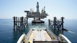
Computer modeling techniques for fire and gas detection systems can optimize the number and position of detectors for both land and offshore installations, as shown by the application of this technique on the Shell Philippines Exploration BV-operated Malampaya deepwater gas project, off the Philippines.
The prime objective of this modeling is to protect personnel and safeguard the environment, but the technique can also reduce capital expenditure and operating costs.
Shell Global Solutions' fire and gas detection modeling technology draws on more than 20 years of experience in hazards and risk management within the Royal Dutch/Shell Group, including extensive field trials to study flame and gas dispersion behavior and to evaluate safety instrumentation.
The type of sensors and their locations are critical in attaining the required coverage, but Shell Global Solutions' experience shows that the design of traditional fire and gas systems is frequently less than optimal. Current systems often are either over-engineered, because of the philosophy that if in doubt add more, or under-engineered, which obviously presents more risk. The judgment of even a highly skilled engineer can produce diverse degrees of detection efficiency in different situations.
Shell Global Solutions based its fire and gas mapping methodologies on infrared (IR) technology, supported by in-house testing of the detection products already on the market. It has proven the application software in the field and Lloyd's Register PLC's oil and gas business unit is considering using the software to verify designs.
Benefits of the technique include:
- Fit-for-purpose detection at minimum cost.
- Significant savings on capital expenditure and operating costs.
- Reduced design times.
- Improved reliability.
- A clear compliance audit trail.
The model has the advantage of being extensively tested on land and offshore operations by Shell companies in such projects as Anasuria and Cormorant in the North Sea, North Rankin and Cossack-Pioneer off Australia, Champion 7 and Ampa-Fairley off Brunei, and Nigerian operations.
Shell Global Solutions also maintains a safety instrumentation website where Shell operating companies can share experiences on the various detection products on the market. The use of the fire and gas mapping methodologies is now a requirement under the Shell Expro Code of Practice.
For about the last 2 years, Shell has made this modeling technique available to non-Shell customers.
Malampaya
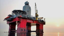
A review of safety requirements for the Malampaya deepwater gas project provides an example of the value of this technique. The platform's design engineers commissioned the work to ensure that detection equipment coverage meets quantitative risk analysis (QRA) recommendations.
The Malampaya platform design allows it to be operated with limited personnel, typically 14 for day-to-day operations and 44 for major maintenance programs.
The modeling aimed to ensure that QRA targets are met with maximum up time: in other words, to achieve the correct configuration of fire and gas detection equipment for safe operational availability and minimum maintenance.
The computer modeling demonstrated that required coverage could be achieved with far fewer flame, flammable gas, and toxic-gas sensors than originally proposed. Compared to the original design, the mapping project eliminated 61 flame, 52 flammable gas, and 103 toxic-gas sensors.
Estimated savings are about $1 million on capital expenditure and $5 million on operating and maintenance costs over the planned 25-year working life of the platform.
Methodology
The software used by Shell Global Solutions to position flammable gas detectors considers wind strength and module ventilation for calculating the probability of a given release being detected.
The program accommodates both line of sight (LOS) and point IR detectors and considers postulated leak locations throughout the module. Positioning depends on factors such as critical gas volumes, or potential leak rates, and the heat and material statistics for the process.
The modeling determines the type of detector to install by considering the most probable leak scenario and whether dispersion will be pressure-driven, result from evaporation, or from a combination of events. At each modeled leak location, the program calculates the probability of the specified gas cloud or leak rate being detected together with the likely scenario when one detector is out of service.
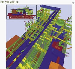
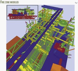
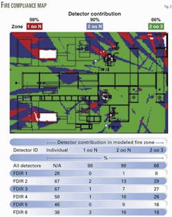
Flame detector placement and compliance software operates on a 3D model of the fire zone to identify objects that could impair a detector's performance. The system considers field-of-view restrictions and the detector's response to different fuel scenarios. The result is a fire compliance map that shows detector configurations and coverage, again even with one detector out of operation.
The objective is to meet safety requirements fully and to ensure that every eventuality is covered, including detector faults that could result in unnecessary automatic shutdowns and very expensive breaks in production.
Fig. 1 shows a simplified 3D fire zone to be modeled with Fig. 2 showing the generated flame map coverage for this fire zone.
To produce a map, the software takes the drawing output (DXF) from the CAD package and turns this into a walk-through model that is used in conjunction with the characteristics of the detector and the required detection sensitivity. The map shows the coverage afforded by each detector and the coverage that is shared by two or more detectors. This is important if detectors need to be combined logically for safety or other reasons.
The statistics for each point enable engineers to judge the safety and economic value of each detector.
The software also provides the required detector mounting positions and viewing angles.
The author
Mike Welch is a principle engineer at the Cheshire laboratories of Shell Global Solutions, joining Shell in 1971. He has been involved for more than 15 years in front-end safety engineering and has led the development of various commercially available safety sensors.
