Pipeline end-sled design for gulf lateral sets several benchmarks
Installation in 1999 of Discovery Producer Services LLC's Green Canyon Block 209 lateral in the Gulf of Mexico represented several important achievements.
Among them were:
- The deepest gulf use of double-submerged-arc welded line pipe.
- To date, the largest and highest pressure rated diverless connectors (16-in. and 12-in. ANSI 1500 class).
- Establishment of a dual-diameter expandable and piggable deepwater natural gas transmission system.
The successful use of large diameter, high-pressure diverless connectors will assist establishing future pipeline transmission infrastructure beyond the continental shelf.
The primary focus of this article is on design, fabrication, testing, and installation of the lateral's pipeline end-sleds (PLES) and 12-in. OD rigid interconnecting jumper on Green Canyon 209.
Following are the technical challenges addressed:
- PLES site selection and survey.
- Design and layout of equipment-diverless connectors, valves, and piggable "Y."
- Expansion and flexibility-design and testing of a rigid jumper connection.
- Installation in 3,000 ft water depths including contingency leveling of a PLES to make a rigid jumper connection.
The Green Canyon Block 209 lateral (formerly referred to as the Allegheny Lateral) is a 27 mile, 16-in. OD natural gas pipeline running from a subsea tie-in on Discovery Gas Transmission's 30-in. mainline on Ewing Bank 873. British-Borneo's Allegheny mini-tension-leg platform (TLP) in Green Canyon 254 was connected to the Green Canyon 209 Lateral with a 3 mile, 12-in. OD gas export pipeline.
The 16-in. OD portion of the pipeline is designed to transport 350 MMscfd of gas and condensate to the Discovery system. Two PLES units and a rigid interconnecting jumper were successfully installed in 3,000 ft of water, and the entire system was commissioned in summer 1999 on schedule and under budget. Extensive design and contingency planning involved in this aspect of the project allowed for efficient installation. The PLES designs also incorporated features that make the dual-diameter system fully piggable during operation for maximum flow efficiency.
Layout, site selection
Particular attention was given to the site selection for the pipeline interconnection. While the transition point from the 12-in. OD pipeline to the 16-in. OD pipeline, this is also the location for the future tie-in to the 16-in. pipeline.
A combination of area bathymetric surveys, flexibility analyses, system expansion, and installation considerations was used in selection and confirmation of an appropriate site.
Four factors controlled selection of the pipeline route:
- Restricted departure angle from the mini-TLP.
- Significant bottom features.
- Avoidance of chemosyntheic communities
- Block leaseholder objections.
These factors dictated choice of a preliminary route and performance of a hazard survey. The survey included the collection of geophysical and bathymetric data, location of magnetic anomalies, and drop core samples.
The orientation of the TLP required a northwesterly departure angle. The tie-in point to the existing Discovery system was slightly northeast of the TLP location. Three wells and the departing oil export pipeline also needed to be avoided.
Previous mapping of the sea bottom, confirmed by the hazard survey, indicated several significant features to avoid. Most notable were three seamounts and an escarpment near the TLP site. Fig. 1 shows the route and bathymetry in the area near the Allegheny field.
Further north along the route, proposed exploration prompted block-leaseholder objections during the permitting process. The route heading was adjusted to avoid interference with future drilling activities.
Several blocks were also identified as possible locations for chemosynthetic communities. Efforts were made to avoid these blocks as well. Pre-pipelay ROV video surveys were performed to ensure these communities did not exist along the proposed route or within the right-of-way.
The key requirement in selecting a site for the PLES units was level terrain. The use of vertical collet connectors on a rigid interconnecting jumper dictated a strict levelness requirement to prevent installation problems.
Because the site will also serve as a future tie-in point, a larger area of level terrain is needed to accommodate a future PLES and jumper as the pipeline system expands.
The hazard survey identified an area within Green Canyon Block 209 as a probable site. This area is in a flat valley between two of the major seamount features (Fig. 1). The drop cores and geophysical sub-bottom profiles showed a soft clay bottom in the area that would allow for consistent settlement of any equipment placed on bottom.
The location also allows for system expansion from major gas discoveries to the south and west of the site. Although more challenging, an approach from the north is also possible.
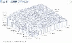
A deep-tow, multibeam swath bathymetry system was used to acquire bathymetry data during the hazard survey. The seafloor contours were provided in 10-ft increments. Full bathymetric charting with a remotely operated vehicle (ROV) was performed on a 400-ft by 400-ft area. The charting system provided seafloor contours to within 6-in. to provide verification of the site.
The results of the ROV survey described the site as an "area of uniformity" with a very gradual northeast-to-southwest slope showing a very shallow gradient of 0.8° (Fig. 2). During the ROV bathymetry charting, an acoustic transponder frame was placed on bottom to serve as a benchmark location for future survey.
Lastly, the pipeline hydraulics were reviewed to confirm acceptable flow characteristics with the change in pipe diameter from 12-in. to 16-in. at the selected PLES location.
Flexibility, installation analyses
With the PLES site and pipeline headings finalized with the results of the hazard survey, the position and configuration of the interconnecting jumper between the two pipeline segments were the next concerns.
The selected vertical, diverless collet connectors had a bending strength equal to the connecting pipe, but the torsion resistance at the sealing face was significantly less than the pipe. The hydraulic analyses showed the transported gas and condensate would be at ambient temperature well before the PLES site; therefore no thermal expansion of the pipeline was expected.
Because the pipeline is unburied and not restrained by soil, pipeline growth from internal pressure was a concern, particularly during hydrostatic testing.
A pipe-stress-analysis software package analyzed the configuration and layout of the connection between the pipeline segments. The software allowed for the complete pipeline to be modeled, provided an approximation of the restraint from limited pipe and soil interaction, and gave design-code compliance documentation.
Three general jumper configurations were analyzed: inverted U shape, horizontal Z shape, and M shape. Following are the design parameters analyzed:
- Torsion at the mating face is limited to 93,000 ft-lb.
- Bending stress must comply with ASME B31.8 combined stress allowable.
- Maximum jumper length is 114 ft.
- Minimum jumper length is assumed to be 40 ft.
The jumper would be installed and hydrostatically tested with the 12-in. OD pipeline.
The approach angles to the PLES site of the two pipeline segments could not be modified.
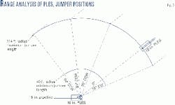
The relative angle between the interconnecting jumper and PLES units and dimensions of the jumper were varied until all the design parameters were met. Fig. 3 shows the range of jumper and PLES orientations analyzed.
During the analysis, use of the more complex Z and M shaped jumpers provided no significant advantage in reducing the jumper loads and stresses. The simple inverted U shaped jumper was then chosen for the remainder of the analyses. The inverted U jumper is also advantageous from both a fabrication and installation viewpoint.
The optimum jumper length, which minimized both the bending stress and torsion at the mating face, was found to be 97 ft. This jumper was then used to determine the operational forces that the structural components of each PLES unit were required to withstand. A further analysis of an expanded system was also performed.
With the 12-in. jumper installed, a 16-in. jumper was modeled into the future tie-in connector. The approach angle of the future connection was varied to ensure the 12-in. jumper would be able to provide the necessary flexibility without becoming overstressed or leak.
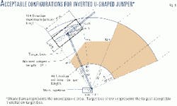
Fig. 4 shows the area of acceptable configurations for an inverted U shaped jumper: that is, those configurations satisfying the design parameters above.
The layout of the PLES units could not be finalized until the proposed design and installation method of each unit were determined. The two pipeline segments were to be installed by different contractors.
The 16-in. segment was to be installed with an S-lay vessel; consequently, the contractor preferred "stalking on" the PLES then lowering the pipeline to the seafloor. The 12-in. segment was to be installed with a J-lay vessel; this contractor developed a "stab-and-hinge-over" structure that would allow initiation of pipeline with the PLES unit.
The project team required a 30-ft clearance radius of any cables used for installation from either of the structures as well as minimized disturbance of the bottom on the PLES site for future expansion. The minimum cable length required to initiate the 12-in. pipeline was 150 ft.
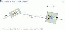
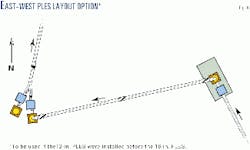
There was no single layout that would satisfy both the design parameters for stress and flexibility and the necessary cable clearance to prevent damage to an installed structure. Figs. 5 and 6 illustrate the two layouts developed, depending on which PLES unit was installed first. The 16-in. pipeline segment and PLES was installed first and the layout shown in Fig. 5 was used.
Jumper analyses, testing
The initial stress and flexibility analyses had concentrated on the operational loadings of the connected system of interconnecting jumper and PLES units. The interconnecting jumper, however, is the key element in the system. Proper and efficient installation was crucial to the success of the project.
Three additional studies verified the integrity and performance of both the piping and collet connectors: finite-element analysis (FEA), flexibility and rigging, and system integration test (SIT).
The flexibility analysis provided a macroscopic view of the stress condition within the jumper piping. The connections between the piping system and the collet connectors could not be accurately modeled with the simplified beam theory.
The jumper piping and portions of the collect connector were modeled in a general FEA package. Changes in both material thickness and behavior and their impact on the stress distribution in the jumper could be examined.
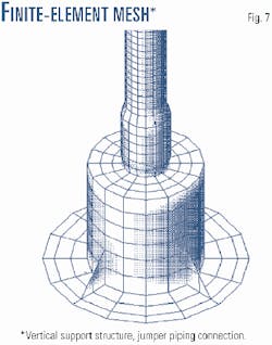
The structure was modeled with a mesh of quadrilateral plate elements. Circular cross sections were divided into sixteen segments, yielding a node-point mesh density of 2.5 in. around the circumference of the jumper and 3 in. along its length. The mesh density in the collet connector and the vertical support structure were scaled proportionately.
Fig. 7 shows the finite-element mesh at the base of the jumper and the vertical support structure. The model included a total of 9,320 node points, 9,236 elements, and 55,776 degrees of freedom.
Before the modeling of the full geometry of the jumper and supporting structure, a model of the upper 91-ft horizontal section (horizontal length between bends) was developed, with a uniform distributed load and idealized boundary conditions at both ends.
Results from the FE model were compared with classical beam-theory calculations of displacement, flexural stress, and hoop stress. Values agreed to within about 2%, confirming the validity of the selected mesh density.
Boundary conditions, in the form of specified displacements, were applied around the base of the vertical-support structure. The values of the 6-degrees-of-freedom displacement were based on results of the hydrotest condition modeled in the flexibility analysis. These displacements were applied at four points around the perimeter, at the base of each end of the model.
Rotational displacements were transformed into vertical displacements at points on either side of the axis of rotation. The displacement components were then resolved into vector form and applied as boundary elements.
Gravity loads were applied as a series of uniformly distributed forces acting downward along the top of the jumper better to account for the buoyancy of the components. Pressure loads were applied as a uniform internal pressure of 1,970 psi throughout the length of the pipe. The applied pressure represents the differential between the internal test pressure of 3,300 psig and the ambient external pressure of 1,330 psig.
Other than at the base of the jumper and in the upper corners, the hoop stress (approximately 14,600 psi) due to internal pressure load is the dominant component. The stresses were generally in the range of 15,000-30,000 psi, approaching but not exceeding 40,000 psi in the most highly stressed areas, and well less than the allowable stress of 60,000 psi.
The analysis performed led to the conclusion that the stresses expected under the specified conditions of loading were within allowable limits.
In preparation of a full-scale system integration test, the jumper was analyzed to verify the piping would not become overstressed as it was lifted and moved during the various tests. This analysis also allowed various rigging schemes to be quickly modeled in an effort to minimize the rigging time.
The primary concern was achieving the proper jumper flexibility to match the anticipated orientation of the PLES units on the seafloor. A collet hub verticality of ±3° was required of the PLES installation contractors.
The collet connector would be able properly to seal with a maximum axial offset of 3° at the mating face. Detail design of the collet connector's installation guide structure, however, indicated an axial offset greater than 0.5° could cause the male and female guide structures to jam if they were both held rigid.
The interconnecting jumper would therefore need to be flexible enough to absorb any axial offset and allow the female connector to slide over the male hub mounted to the rigid PLES.
Analysis of the various lifting points indicated that the jumper would have adequate flexibility to re-orient the female collet connector to align with a 3° axial offset. This flexibility could also be achieved without overstressing the jumper piping both ashore during system integration testing as well as under operating and hydrotest conditions.
The results of this analysis were used in design of a multi-position clamp and lifting eye to allow the jumper installation contractor to vary the rigging quickly during the systems integration test. The permanent lifting clamp would also make the final lifting location, determined during SIT, repeatable in the field.
Before the systems integration test (SIT), each component of the system-valves, collet connectors, and ROV interfaces-underwent factory acceptance testing to verify functionality. Once the three components making up the PLES site-12-in. PLES, 16-in. PLES, and 12-in. interconnecting jumper-were fabricated, a systems integration test was performed.
The test was jointly managed and directed by the jumper installation contractor and the project management team. The main focus of the test involved performing the following tests: jumper installation and seal; horizontal misalignment; vertical misalignment; angular misalignment; seal removal and replacement tool; and installed jumper system hydrostatic.
The most critical of these tests was the angular misalignment test. During it, each PLES unit was oriented so that the male collet connector hub was 3° off vertical alignment. The interconnecting jumper would then be "installed" by being lowered onto the hubs.
As a final test, once the collet connectors were mated, the complete system would be flooded and hydrotested. To ensure the jumper piping would not be damaged during this test, strain gauges were installed at the critical areas found during the FEA and flexibility analyses. The stress in the pipe would then be monitored in real time during the test to prevent any accidental damage.
After proper orientation of the PLES units, the interconnecting jumper was lowered, the collets engaged, and the system flooded and tested without incident. The successful completion of all the SIT tests provided the installation contractor the necessary confidence in all the equipment.
16-in. PLES
The purpose of the pipeline end-sled is to provide an installation structure to which to attach these piping components and then lower them to the seafloor in the desired orientation. The structure must not only withstand the installation loads while being lowered to the seafloor but also retrieval to the surface should a failure occur.
The 16-in. pipeline initiates with piping designed to accommodate future expansion. The primary components are 16-in. and 12-in. ANSI 1500 class male hubs for the diverless collet connectors and a 16-in. piggable "Y."
The Allegheny TLP gas export line uses the 12-in. connector, leaving the 16-in. connector free for future tie-in and system expansion. Also included in the piping are 16-in. and 12-in. ANSI 1500 subsea ball valves to isolate each pipeline segment.
Incorporated in the ball valves are complete ROV interface panels allowing not only operation of the valves but also maintenance. Each ROV interface allows for both lubrication and sealant injection to the valve.
With the piggable Y oriented horizontally and use of different sized collect connector hubs and valves, the piping was arranged so that the center of gravity was along the centerline of the pipeline.
Assuming the connecting structural components would follow the same philosophy, this would minimize the tendency of the PLES to rotate during installation. Rotation of this PLES was critical because the installation contractor was held to the 3° verticality requirement for both collect connector hubs.
Structural components
The contractor installing the 16-in. pipeline was responsible for the installation concept and design of the structural components. The installation concept was to retrieve the end of the pipeline, weld on the PLES unit, then lower the completed assembly by a hinged yoke on the structure, typical of similar installations.
The structural components can be grouped into two functions: installation loaded members and in-place loaded members.
The members subjected to the in-place loads attach and support the piping components to the structural components. The in-place loads consisted of the jumper loads developed during the system-flexibility analyses, the dead loads of all components, and an applied pipeline torque.
Installation experience has shown that the pipeline will tend to rotate as it is retrieved from the seabed, particularly for S-lay pipeline installation. Since the PLES will achieve a fixed orientation on bottom, there will be some residual pipeline torque. The applied torque used for the in-place loads was calculated from a 180° pipeline rotation.
By far the most significant loads on the PLES structural members are during lifting and installation of the completed unit. Four installation load cases and two lift cases were used in the design of the PLES structure:
Installation Load Cases 1 and 2 represent the PLES and pipeline above water as it is suspended by the installation vessel. Installation Cases 3 and 4 represent worst-case conditions as the PLES and pipeline are being lowered to the seafloor.
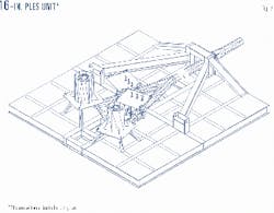
The two lift cases represent the PLES unit being transported and moved into position for attachment to the suspended pipeline. Fig. 8 is an isometric drawing of the completed 16-in. PLES. The completed PLES has a 30 by 30 ft footprint and weighs approximately 60 tons.
Two conditions governed design of the mudmat used to support the structure on bottom: the very soft clay seafloor and the physical limitations of the installation vessel.
The geotechnical report stated the shear strength of the soil 3 ft below the seabed as 43 lb/sq ft. This value was assumed to represent the seabed elevation as well for the mudmat design.
To minimize the soil pressure and therefore the long-term settlement, the plate was placed on the "top" of the supporting structural beams. This would allow the large structural members required for the installation loads to settle into the bottom, leaving the piping components just above or at the seafloor elevation, depending on the final settlement.
Designers anticipated this would allow the PLES to settle to the slope of the seafloor, assuming consistent soil conditions, preventing any verticality problems.
The metrology performed before jumper installation had the 12-in. collet connector hub less than 2° off the vertical axis. The structure had also settled as predicted with the mud mat plating at the sea bottom elevation.
12-in. PLES
A 12-in. pipeline from Allegheny field in Green Canyon Block 254 will supply the initial volume of gas to be transported in the 16-in. pipeline segment. This pipeline segment will terminate with its own pipeline end-sled to provide the supporting structure for the collet connector.
Although similar in function to the 16-in. PLES unit, the 12-in. PLES incorporates a different installation structure as well as a unique articulating mudmat for contingency leveling.
The piping components on the 12-in. PLES are simply a 12-in. ANSI 1500 class ball valve and 12-in. ANSI 1500 class male hub for the diverless collet connector. While the design pressure of the Allegheny mini-TLP piping is 2,220 psig, the use of ANSI 1500 class valves would allow the pipeline to be hydrostatically tested with the valve in the closed position should the pressure cap on the collet connector hub leak.
Future system expansion once the Allegheny field is depleted would require higher operating pressures should the 12-in. pipeline be extended to deeper waters warranting the use of ANSI 1500 components.
The installation contractor was again responsible for the installation concept and design of the structural PLES components.
The 12-in. pipeline segment was installed with a J-lay vessel and the contractor wished to initiate pipelay at the PLES site. To accomplish this, the contractor proposed to the project team a hinged structure, similar to a "stab-and-hinge-over" design.
The piping components would be attached to one side of the hinge point (the "yoke") and the mudmat attached to the other (the "sled"), remaining horizontal as the pipe is lowered from the J-lay tower. Once the PLES is on bottom, a temporary cable would hold it in place while pipelay is initiated.
As the vessel would lay away, the structure would hinge down and lock in a final, horizontal position.
As with the 16-in. PLES, both operational and installation loads were used to design the structure. Because pipelay would initiate with the PLES attached to the pipeline, however, the installation loads were far less.
The following load cases were used in the design of the PLES structural elements:
- Lift-load case: PLES lifted in the horizontal position at the four corners.
- Installation-load case: Yoke and pipeline vertical, sled and mudmat horizontal, all hanging by the end of the pipeline.
- In-place load case: PLES on the seabed with dead loads, jumper loads, and pipeline expansion loads applied.
- Recovery-load case: PLES hanging near vertical by the recovery hook with flooded pipeline loads pulling downward.
The design was governed by the recovery-load case in which the PLES and pipeline would be retrieved to the surface in a flooded condition.
The ability to install each PLES unit within the ±3° verticality requirement was one of the greatest concerns to the project team. The size and mass of the 16-in. PLES precluded use of most leveling systems.
The smaller size of the 12-in. PLES allowed the project team to incorporate a contingency leveling system to be used as a last resort for the interconnecting jumper installation. This system would provide a means of correcting the attitude of the 12-in. PLES should either PLES settle unevenly and therefore out of the vertical tolerance before jumper installation.
The leveling system consists of a mudmat and four screw jacks. The mudmat was designed similar to the 16-in. PLES, producing the same soil-bearing pressure.
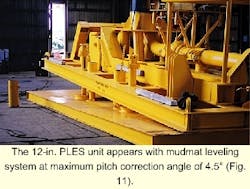
The four screw jacks attach the mudmat to the structural sled. Each jack is independently operated via an ROV and torque tool. The base of each jack is free to rotate giving a ±4° adjustment in both pitch and roll axes from the installed position.
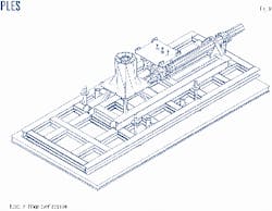
Figs. 9 and 10 show an isometric of the 12-in. PLES in its "stab" and "hinge-over" configurations, respectively. Fig. 11 shows the mudmat leveling system during the systems-integration test at its maximum adjustment angle.
The 12-in. PLES is 16 ft wide by 32 ft long and weighed approximately 38 tons. The measurements performed before jumper installation showed the collet connector hub approximately 1.5° off the vertical axis. As with the 16-in. PLES, the structure had settled as predicted with the mudmat plating at the sea-bottom elevation.
Acknowledgments
This work was supported by Discovery Producer Services LLC and Project Consulting Services, MPC International, Allseas Construction Contractors SA, J. Ray McDermott, and Global Industries Offshore.
The author
Michael R. Istre is lead design engineer for Project Consulting Services Inc., Metairie, La., for which he has been employed since 1996. Before joining PCS, he was employed as a research and development project manager and supervisor for Laitram Corp., Harahan, La. Istre holds a BS (1992) from the University of Southwestern Louisiana and an MS (1994) from the University of Texas, Austin, both degrees in mechanical engineering. He is a member of ASME, the National Society of Professional Engineers, and the Louisiana Engineering Society (LES). Istre is a registered professional engineer in Louisiana, Alabama, and Florida.
Based on a presentation to the Offshore Technology Conference, Apr. 30-May 3, 2001, Houston.


